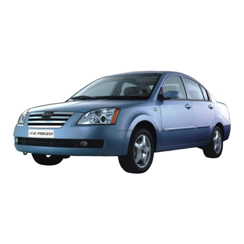
Chery A21 2005 User manual

Terminal
START
L0CK
Position
0N
ACC
ST2ACC AM2IG2
AM1
STARTANDCHARGESYSTEM
CIRCUITDIAGRAM
NO.03/01
A21-2005
StarterRelay
IgnitionSwitch
Generator
Starter
Relay ACC
1
Relay ACC
2
I
gnition
S
witch
Relay
Storage
Baterry
To
instrument
16#

A21-2005 NO.03/02
CIRCUITDIAGRAM
ABS SYSTEM
To Brake Switch
ABSControl
Left
Front
Wheel
Sensor
Right
Front
Wheel
Sensor
Left
Rear
Wheel
Sensor
Right
Rear
Wheel
Sensor

A21-2005 NO.03/03
CIRCUITDIAGRAM
AIRCONDITIONINGSYSTEM
Blower
A/C Pressure
Switch
CyclingMotor
ModeDamperMotor IncorporatedDamper Motor
Outer
Temperature
Sensor
To Instrument
7#
To W
iper
M
otor
2#
Governor
Resistor
Inner
Temperature
Sensor
WaterT emperature S
ensor
SunlightSensor
To D
iagnostic
C
onnector
7#
To D
efrost
S
witch
2#
A/CControl

A21-2005 NO.03/04
CIRCUITDIAGRAM
AUDIO SYSTEM
Audio System
LeftRearSpeaker
RightRearSpeaker
LeftFrontSpeaker
RightFrontSpeaker
LeftFrontDoor
Speaker
RightFrontDoor
Speaker
Antenna
SteeringWheelShortcutKey
Front ISUPP3/3

A21-2005 NO.03/05
CIRCUITDIAGRAM
AIRBAGSYSTEM
Airbag Control
DriverAirbag FrontPassengerSideAirbag
ToInstrument 17#
FrontPassenger
AirbagLockSwitch
LeftFrontPretensioner
SeatBelt
DriverSideAirbag FrontPassenger
SideAirbag
LeftImpactSensor RightImpact
Sensor
RightFrontPretensioner
SeatBelt
ToDiagnostic Connector 7#
ToInstrument 24#
ToISUPE2/16

TerminalResistor
A21-2005 NO.03/06
CIRCUITDIAGRAM
INSTRUMENTSYSTEM
Instrument
Manual Brake Switch To Airbag Control
10#
Oil Pressure Switch
Fuel Level Sensor To Airbag Control
47#
Brake Fluid Level Sensor
To Speed Sensor 2#
To Front ISU PE1/2
To Sunroof Module
3#
To Diagnostic Connector
7#
To Generator Terminal
1#
To Automatic A/C Module J
Brake Shoe Lining Alarm Switch
Brake Shoe Lining Alarm Switch
Brake Shoe Lining Alarm Switch
Brake Shoe Lining Alarm Switch

Terminal Resistor
08
CIRCUIT DIAGRAM
NO.03/07
ENGINE SYSTEM
A21-2005
Engine ECU
Anti-theft Control
Ignition Coil
Rear Oxygen Sensor
Nozzle 2
To AntitheftControlA1
To FuseFB15
EMSRelay
BrakeSwitch
Speed Sensor
Crankshaft Position Sensor
Electronic Accelerator
To Fuse FB5
Coolant Temperature Sensor
Knock Sensor
To ABS6
To FrontISU PE2/22
VortexControlValve
ExhaustTiming Solenoid Valve
Air Flowmeter
Electronic Throttle Valve
CamshaftPhaser
CarbonCanister Solenoid Valve
IntakeTimingSolenoid Valve
OilTemperatureSensor
To Instrument27#
ToA/CPressureSwitch 3#
Compressor Relay
Oil Pump Relay
Oil Pump
ClutchSwitch
Power Steering Switch
ToElectronicControlHeadlamp Switch 6#
To AntitheftControlA4
Nozzle 4
Nozzle 3
Nozzle 1
CamshaftPhaser
FrontOxygenSensor
To A/CPressureSwitch2#

A21-2005
REAR ISU SYSTEM
NO.03/11
CIRCUIT DIAGRAM
12
Radar Module
To Front ISU A29
Trunk Lamp
Trunk Switch
ContactSwitchof LeftRearDoor
Regulator Switchof RightRearDoor
Regulator Switchof LeftRearDoor
To Front ISU A30
High MountedStopLamp
Trunk Lock Actuator
LeftTurn Light
RegulatorMotorofRightRearDoor
Rear Windshield Glass Heaterresistor
LeftBackupLamp
LicenseLamp
LeftPositionLamp
LeftRear Regulator Motor
LeftProbe
ContactSwitchof RightRearDoor
RightPosition Lamp
RightRear Fog Lamp
RightTurn Signal Lamp
RightBackup Lamp
Middle Probe
RightProbe

A21-2005 NO.03/08
09
FRONT ISU
Front ISU
LockActuator ofLeftFrontDoor
To Audio 15#
To Ignition Switch 3#
FrontCeilingLight
To Double Switch 6#
Low-tone Horn
Fanfare Horn
Sun VisorLamp
GloveBoxLamp
Key Loop Lamp
DefrosterSwitch
Low Beam RelayHigh Beam Relay
To Rear ISUA22
To Rear ISUA6
KeySignalSwitch
To SunroofModule 4#
To A/C Module 14#
NigntLampAdjusting Switch
CIRCUIT DIAGRAM
LeftFrontPosition Lamp
RightFrontPosition Lamp
RearCeiling Light
RearFogLampSwitch
FrontFogLamp Switch
ContactSwitchof LeftFrontDoor
ContactSwitch ofRightFrontDoor
FrontFog Lamp
RightFrontTurn Signal Lamp
RightSide Turn Signal Lamp
LeftFrontTurnSignalLamp
LeftSideTurn Signal Lamp
RegulatorMotorofRightFrontDoor
RegulatorMotorofRightFrontDoor
Regulator Switchof LeftFrontDoor
LockActuator of RightFrontDoor
LockActuator ofLeftRearDoor
LockActuator ofRightRearDoor

2
CHAPTERIENGINEPARAMETERAND SPECIALTOOL
I.TECHNICALDATADESCRIPTION
ENGINEFEATURE
Enginemodel SQR481H
Enginetype Fourcylinders, water-cooled,in-linedoubleoverhead
camshaft, 16 valves, controllableburningrate(CBR)
andvariablevalvetiming (VVT)
Cylinderdiameter(mm) 81
Pistonstroke 77.5
Displacement 1.597
Compressionratio 10.5
RatedPower(netpower) 87
Revolutionatratedpower(RPM) 6200
Maximumtorque (Nm) 275
Revolutionatmax. torque (RPM) 4300
Minimumfuelconsumptionrate 275
PDFcreated withpdfFactoryProtrialversion www.pdffactory.com

4
III. ENGINENUMBERPOSITION
CHAPTERIIENGINEACCESSORIES
SECTIONIENGINETIMINGCALIBRATION
1. Dismantledynamobelt
Usewrenchtoclampthetensionpulleybolt,
screwitcounterclockwiseanddismantlethe
generatorbolt.
Position ofEngineCylinderBlockNumber
EngineOil Dipstick
PDFcreated withpdfFactoryProtrialversion www.pdffactory.com

5
2.Dismantletherightenginemounting
bracket
Usesmallcranetohoisttheengine,
dismantletheboltsofrightsuspensionand
liftdowntherightmountingbracket.
3.Dismantlecrankshaftpulley
Shiftthecarintothe5thgear,steponthe
brake,anddismantlethefixedboltof
crankshaftpulley.
4.Dismantlethetiming beltcover
Dismantletheuppercoverandlowercoverof
timing beltrespectively.
UpperCover
LowerCover
PDFcreated withpdfFactoryProtrialversion www.pdffactory.com

6
4. Dismantletiming belt
Loosenthecentralfixedboltoftension
pulleyoftiming belt,dismantlethetiming
belt.Meanwhile,loosenthehollowstaybolts
connectingtheairintakeandexhaust
camshaftpulleysandthecamshafts.
Carryoutdetailedinspectiononvariousportionsoftiming belt.Ifanyoneshowninthe
figureoccurs, youshouldreplace withnewspareparts.
(1)Chapofback-siderubber
(2)Chapofdedendum, chapofseparatedcordfabric.
(3)Wearing, gearmissing andincompletegearofcordfabric.
(4)Abnormalwearingofbeltflank.
AirIntake
Camshaft
Pulley
ExhaustCamshaftPulley
Idler
CoolantPump
Belt
CrankshaftTiming
TimingBelt
TensionPulley
Chap
Chap
Wearing
PDFcreated withpdfFactoryProtrialversion www.pdffactory.com

7
Evenifnoouterdamageisconfirmed,youshouldalsoreplace thebeltwhenanyofthe
followingconditionsoccurs.
(1)Ifthewaterinthecoolantpumpisleakedandmorewatershouldbefilledcontinuously.
(2)Ifthebeltisspottedwithmuchoilstains,andtherubbermaybedamageddueto
expansion,youshouldreplace thebelt.
5.Dismantlethevalvechambercover
Loosenthefixedboltofvalvechamber
cover, andliftdownthevalvechambercover.
6.Camshaftphasealignment
Rotatethecamshaftandclampthecamshaft
toolintotheeccentricgrooveofcamshaft
sensorsignalpulley.
AbnormalWearing
GearMissing
Belt CoreDesquamation
CamshaftTool
PDFcreated withpdfFactoryProtrialversion www.pdffactory.com

9
7. Crankshaftphasealignment
Screwoff thebulkheadofcylinderblock,
screwthecrankshafttoolintoit,rotatethe
crankshaft untilthecrankshafttool
completelyclampsthecrankshaft.Atthis
time,thecrankshaftcannotrotateclockwise
andcounterclockwise.
8. Mountandstrainthetiming belt
Mountthetiming beltinthepositionshown
inthefigure,useallenwrenchtorotatethe
tensionpulleyinordertostrainthebelt,
fastenthetensionpulleybolt.Andfastenthe
fixedboltofairintakeandexhaustcamshaft
pulleysandthecamshafts.
Torque:120 5Nm.
9. Liftdownthespecialtiming calibration
tools,andthenfastenthevalvechamber
cover, timing beltcover, therightengine
mountingbracketofengine,and
dynamobelt.
CrankshaftTool
PDFcreated withpdfFactoryProtrialversion www.pdffactory.com

10
SECTIONII LIFTINGAND INSTALLATIONOFENGINE
1. Whentheignitionswitchisshutoff,you
canpulloutthebatteryearthcable,
loosenthefastening screw,anddismantle
thebattery.
2. Loosenthecondenserdrainpipe,screw
off theexpandedpotlid, anddischargeall
theanti-freezing solution.
3. Dismantletheairflowlinesbetweenthe
throttlevalvecaseandtheairflowmeter,
dismantlethe(a)leadconnectorofair
flowmeter,(b)leadconnectorofignition
coil,(c)leadconnectorofcanister
solenoidvalve.
4. Removethe(d)thewireharness plug of
watertemperaturesensor,and(e)wire
harnessplug ofairintakeandexhaust
camshaftpositionsensor.
b a
c
e
d
PDFcreated withpdfFactoryProtrialversion www.pdffactory.com

11
5.Removethe(f)theharness plug ofCBR
solenoidvalve.
6.Dismantle(g)theearthcableboltof
cylinderhead,remove(h)thewire
harnessplug ofstartercoil,(i)wire
harnessplugsoffouroilinjectors, (j)
knocksensorplug,(k)wireharness plug
ofthrottlevalvecontroller.
7.Remove(l.)CBR solenoidvalveplugs,
and(m)oil temperaturesensorplugs
8.Loosen(n)generatorpositivepoleoutput,
pullout(o)excitingcurrentharnessplugs
aswellastheplugsofrelevantpartsof
theA/Ccompressor,steeringbooster
pump,oxygensensor,andA/Chigh-low
voltageswitch.. Loosenthefixedboltof
starterharness toconfirmtheplugsofall
partsarecompletelyseparated.
f
i
k
j
hg
m
l
n
o
PDFcreated withpdfFactoryProtrialversion www.pdffactory.com
Table of contents
Other Chery Automobile manuals

Chery
Chery Karry series User manual
Chery
Chery QQ6 User manual

Chery
Chery QQ6 User manual
Chery
Chery A21 User manual

Chery
Chery Tiggo 5 T21 User manual
Chery
Chery QQ3 User manual

Chery
Chery Tiggo 2009 User manual

Chery
Chery Automobile User manual

Chery
Chery TIGGO User manual
Chery
Chery Automobile User manual


