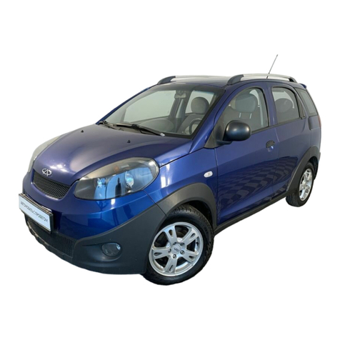
Chery Tiggo 5 T21 User manual

Training Center of After-Sales Department Chery International
Course description
•This course introduces the new technology of Chery T21 vehicle, such as PEPS,
rearview dynamic reversing imaging system, TELEMATICS system etc.
•This course shows the detailed information of engine system, transmission system,
electrical system and chassis system.
•During the course learning, you’ll share the maintenance experience in different part of
T21, which can save your time and makes your work simple.
•After the course training, you will know Chery T21 vehicle well and help you do
maintenance good.
2
MASHINESOFT.COM
09120146259

Training Center of After-Sales Department Chery International 4
Vehicle communication system
PEPS system
Cruise control system
BCM
Window & anti-pinch sunroof system
Anti-theft alarm and locking system
Electric rearview mirror
Sunroof control system
Internal lighting system
External lighting system
Wiper system
Instrument cluster
Audio system
TELEMATICS system
Reversing radar system
Safety airbag system
Electric seat
10
11
12
13
14
15
16
17
1
2
3
4
5
6
7
8
9
Contents
MASHINESOFT.COM
09120146259

Training Center of After-Sales Department Chery International
1. Vehicle communication system
What’s CAN bus?
CAN: Controller area network
In early 1980s, Germany Bosch develops a serial communication protocol to realize the real-time
data exchange between various control units and testing instruments in modern cars.
A half-duplex serial communication protocol;
The communication medium can be double-stranded cable, co-axial cable or optical fiber cable;
Communication baud rate 5K - 1MB/s;
Communication distance 40m-10km.
6
1. CAN-bus
MASHINESOFT.COM
09120146259

Training Center of After-Sales Department Chery International
1. Vehicle communication system
7
Why is the CAN bus installed in the car?
Point-to-point connection between
controllers:
•Increased cost of materials
•Reduced reliability
•Increased weight of the car
Connection between controllers by the serial bus
•Reduction of wiring harness and mounting space
•Reduction of manufacturing cost
•Improvement of real-time reliability of the system
communication
•Improvement of expansion capacity and flexibility
•Adaption to unfavorable working environment
Conventional node communication method CAN bus communication method
1. CAN-bus
MASHINESOFT.COM
09120146259

Training Center of After-Sales Department Chery International
1. Vehicle communication system
8
ICM BCM ABM EMS
CAN_LCAN_H
CAN_H
CAN_L
Double-
stranded
cable
Microcontroller
CAN Controller
TX0 RX0TX1 RX1
+5V
100nF
CAN Transceiver
TXD RxD Ref Rs
Vcc
Gnd
CAN_L CAN_H
Mobile signal
amplifier Transceiver
1. CAN-bus
MASHINESOFT.COM
09120146259

Training Center of After-Sales Department Chery International
1. Vehicle communication system
9
CAN standard data frame format
SOF Mark the starting of a data frame, used for synchronization
ID Determine the arbitration priority level of the message. The lower the ID value is, the
higher the priority level
RTR Used to distinguish the data frame and remote frame (Data frame: RTR=0; remote frame:
RTR=1)
IDE Used to distinguish standard frame and expansion frame (standard frame: IDE=0;
expansion frame: IDE=1)
R Reversed position 0
DLC Including 4 bits, representing the number of bytes containing data in the data field
Data Field With 0-8 bytes, determined by DLC, containing the information contained in CAN data
frame
CRC Used for CRC verification
DEL Identify CRC sequence
ACK Determine that the message has been correctly received by at least one node
EOF Means the ending of data frame
Frame
start Arbitrati
on field
Control
field
Data
field
CRC
field
ACK
field
Frame
end
1. CAN-bus
MASHINESOFT.COM
09120146259

Training Center of After-Sales Department Chery International
1. Vehicle communication system
10
1. The power CAN is a 500kb/s transport network, and terminal resistor is located in ECM/BCM.
2. The body CAN is a 500kb/s transport network, and terminal resistor is located in ICM/BCM.
3. IMMO is built in PEPS system.
4. ESP system utilizes YAM which is integrated in ABM, and the dedicated CAN communication
is provided. 120Ωresistors are located in these two modules.
1. CAN-bus
MASHINESOFT.COM
09120146259

Training Center of After-Sales Department Chery International
1. Vehicle communication system
11
Type of
node Abbrebytion Full English name
CAN
1 ECM Engine Control Module
2EPS Electronic Power Steering
3 TCM Transmission Control Module
4TPM Tyre Pressure Module
5RRM Radio Receiver Module
6ABM Air Bag Module
7SAM Steering Angle Module
8 BCM Body Control Module
9ABS Anti-lock Break System
ESP Electronic Stability Program
10 PEPS Passive Entry & Passive Start
11 CLM Climate Module
12 IMMO Immobilizer
13 ICM Instrument Cluster Module
14 TMM Torque Management Module
15 ALS Auto Leveling System
16 CAM Camera
17 YAM Yaw acceleration Module
Type of
node Abbrebytion Full English name
LIN
1 RSM Rain Sensor Module
2 RADAR Radar Module
3 FLAM Front Left Anti-pinch Module
4 FRAM Front Right Anti-pinch Module
5 RLAM Rear Left Anti-pinch Module
6 RRAM Rear Right Anti-pinch Module
7BS Base Station
1. CAN-bus
MASHINESOFT.COM
09120146259

Training Center of After-Sales Department Chery International
1. Vehicle communication system
12
2. T21 communication bus
–T21 power CAN bus
YAM
ABM/ESP
CAN-H
CAN-L
For YAM sensor dedicated CAN, a 120Ωresistor is located in YAM and ABM respectively.
EMS
CAN-H
CAN-L
TCM
PEPS
ALS
ABM/ESP
TMM
EPS
BCM
BS SAM
YAM
ABM Diagnose
interface
MASHINESOFT.COM
09120146259

Training Center of After-Sales Department Chery International
1. Vehicle communication system
13
2. T21 communication bus
–T21 body CAN bus
High-speed communication network
ICM
CAN-H
CAN-L
CLM TPM
Diagnose
interface
RRM
BCM
1-28 1-27
10
2
CAM
Equipment of CLM double-zone automatic air conditioner;
TPM and CAM are reserved modules now.
MASHINESOFT.COM
09120146259

Training Center of After-Sales Department Chery International
1. Vehicle communication system
14
3. T21 communication bus
–T21 Lin communication bus
RSM is now a reserved module;
LIN1 is only equipped in the car with window anti-pinch function.
PEPS
BS
LIN
RADAR
LIN2
RRDM
RSM
BCM
LIN1
FLAM FRAM RLAM
MASHINESOFT.COM
09120146259

Training Center of After-Sales Department Chery International
1. Vehicle communication system
15
The configuration shall be specified if the T21 module is to be replaced.
–Body control module (BCM)
–Instrument cluster module (ICM)
–Electronic stability procedure (ESP)
–Passive entry& passive start system (PEPS)
–Engine management system (EMS)
–Electronic power steering system (EPS)
–Audio entertainment system (DVD) with Telematics
2. T21 communication bus
MASHINESOFT.COM
09120146259

Training Center of After-Sales Department Chery International
1. Vehicle communication system
16
T21 software configuration process
DTC is found
Connect X-431
Read DTC
⑦Clear DTC
No
No DTC
Right
Yes
Failed, reprogram
Failed , reprogram
Failed ,
reprogram
①Read original BCM
configuration code
②Power OFF, replace
BCM, input the
configuration code.
The code cannot be read
or communication fails.
Wrong
Success
③Read and confirm the
BCM configuration code
④Send VIN to Chery,
and get configuration code
⑤Replace BCM, and
write the car
configuration code.
⑥Whether the BCM
configuration codes are
all F?
Record the code
if it can be read.
2. T21 communication bus
MASHINESOFT.COM
09120146259

Training Center of After-Sales Department Chery International
1. Vehicle communication system
17
Configuration
procedure
Before replacement of body control module, enter “Body control system/Data
stream reading/Body control module configuration information”, and read the
configuration code of body controller. If the said code can be read, record the
code, and execute ②;if the said code can’t be read, BCM is damaged to cause
failure of reading of configuration code or failure of connection, in which case
④shall be executed.
After the body control module is replaced, enter “Body control system/Special
operation/Write body control module configuration code”, and write the
configuration code recorded in ①into the body control module.
Turn the ignition key to OFF and then to ON, and re-enter “Body control
system/Data stream reading/Body control module configuration information”,
read the configuration code of body control module and compare it with the
code read in ①, and manually check whether the entry is correct; if correct,
execute ⑦,and if not, execute ①.
The service station will check information on relevant characteristics of the car
(such as chassis number), and provide it to the after-sales service department
of the sales company and obtain the 196-digit complete vehicle configuration
code from the after-sales service department.
2. T21 communication bus
MASHINESOFT.COM
09120146259

Training Center of After-Sales Department Chery International
1. Vehicle communication system
18
Configuration
procedure
Note: The after-sales service department will enter SAP system in accordance
with relevant car information to find out the material number, and then find out
the 196-digit complete vehicle configuration code in the MES system according
to the material number.
After the replacement of body control module, enter “Body control
system/Special operation/Write the complete vehicle configuration code”, and
write the configuration code recorded in ④into the body control module.
Enter “Body control system/Data stream reading/Body control module
configuration information”, and read the configuration code of body control
module. If all configuration codes are not only F, the writing is successful,
execute ⑦,and if all configuration codes are only F, execute ⑤again.
Enter “Body control system/Clear fault code”, and enter “Body control
system/Read fault”.If the fault code is present, execute ⑤again; if no fault
code is present, disconnect the diagnostic apparatus, and the body control
module is successfully replaced! The operation is finished!
2. T21 communication bus
MASHINESOFT.COM
09120146259

Training Center of After-Sales Department Chery International
2. PEPS system
20
General introduction of PEPS system
–PEPS (Passive Entry Passive Start)
–Passive Entry Passive Start is developed on the basis of the key entry system.
PEPS
Door lock
actuator
Other actuators
Built-in
antenna
BCM
1. General description
MASHINESOFT.COM
09120146259
Table of contents
Other Chery Automobile manuals

Chery
Chery Karry series User manual
Chery
Chery QQ6 User manual

Chery
Chery TIGGO User manual

Chery
Chery Automobile User manual

Chery
Chery A11 2003 Operating instructions
Chery
Chery A1 2009 User manual
Chery
Chery A21 User manual

Chery
Chery Tiggo 2009 User manual

Chery
Chery TIGGO User manual

Chery
Chery A113 User manual


