Operating Principles Air Chicago Express
5-6
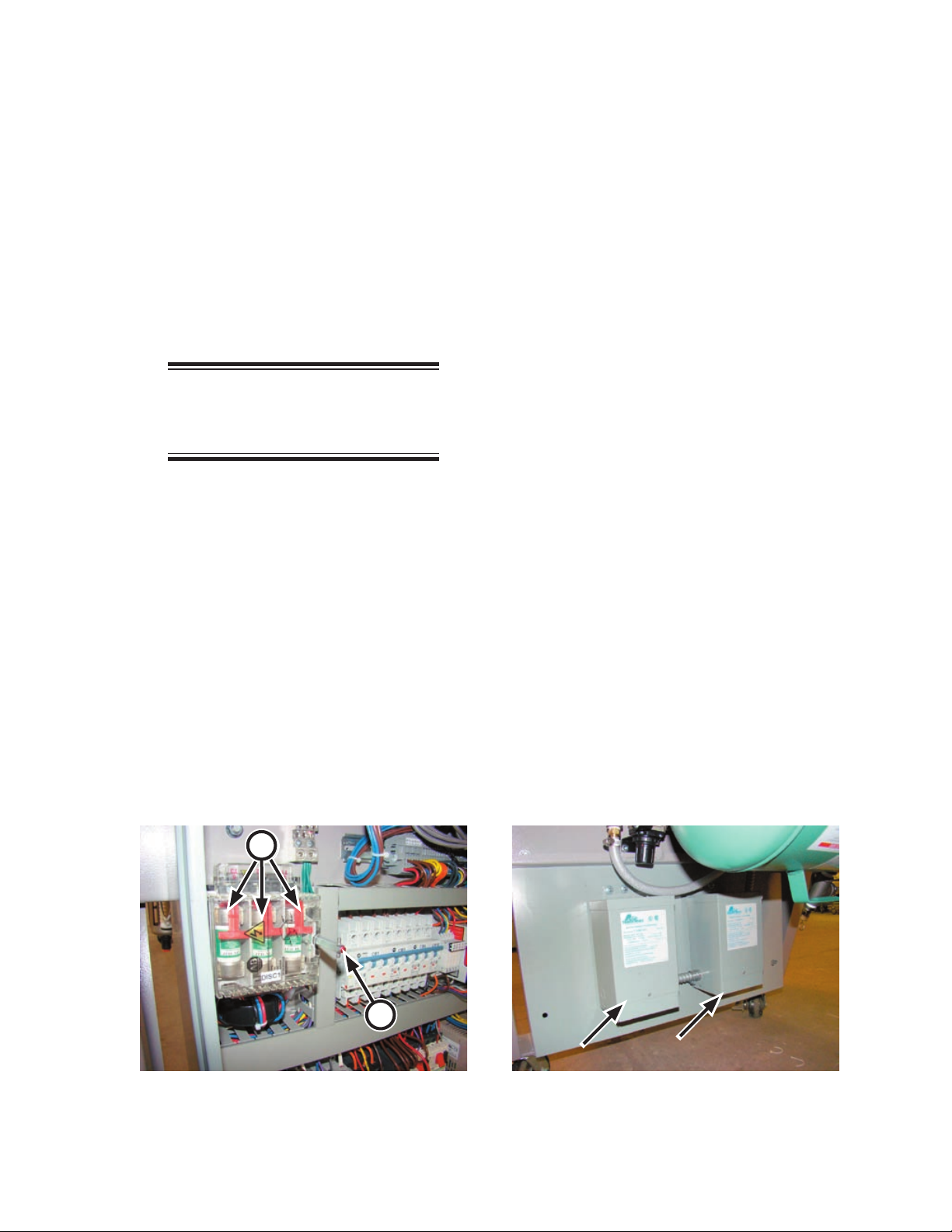
Control System
Control of the machine is done in two areas.
Input from the operator takes place at the
CHI•Touch screen, located on the outside of the
unit. These commands are combined with internal
signals in microprocessor unit.
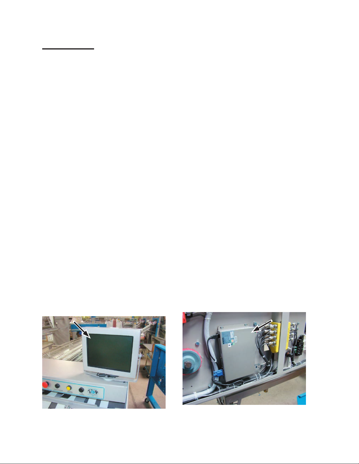
CHI•Touch Screen
Operators control the folder with the Chicago
High Intelligence (CHI) touch screen located
at the right front of the unit (Figure 5-4). The
CHI•TOUCH OPERATION bulletin discusses
the use of this screen.
The touch screen accepts the operator touch
and sends them to the microprocessor unit, which
in turn sends operation and diagnostic messages
to the screen for display.
Communication between the CHI•Touch
screen and the microprocessor unit is handled
via a USB connection.
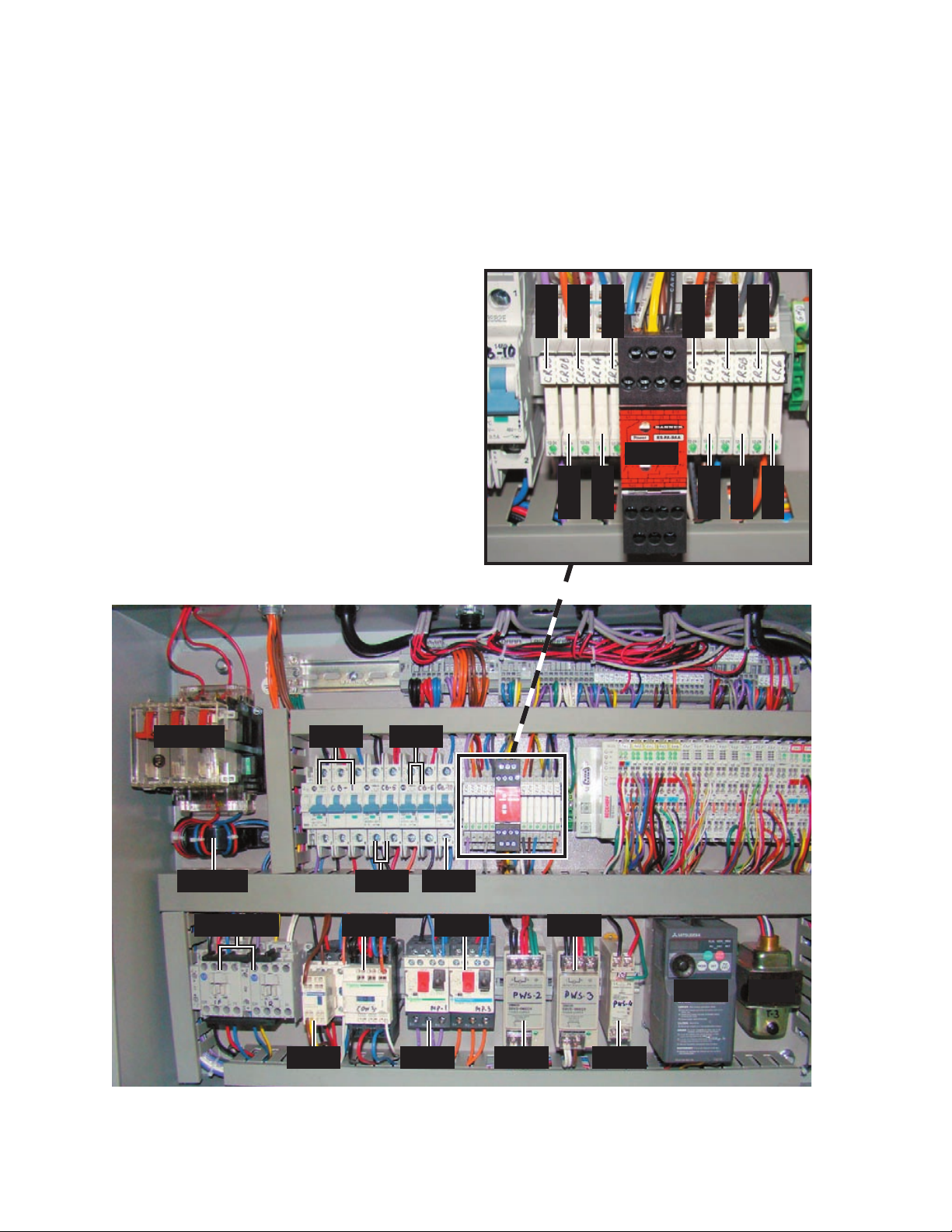
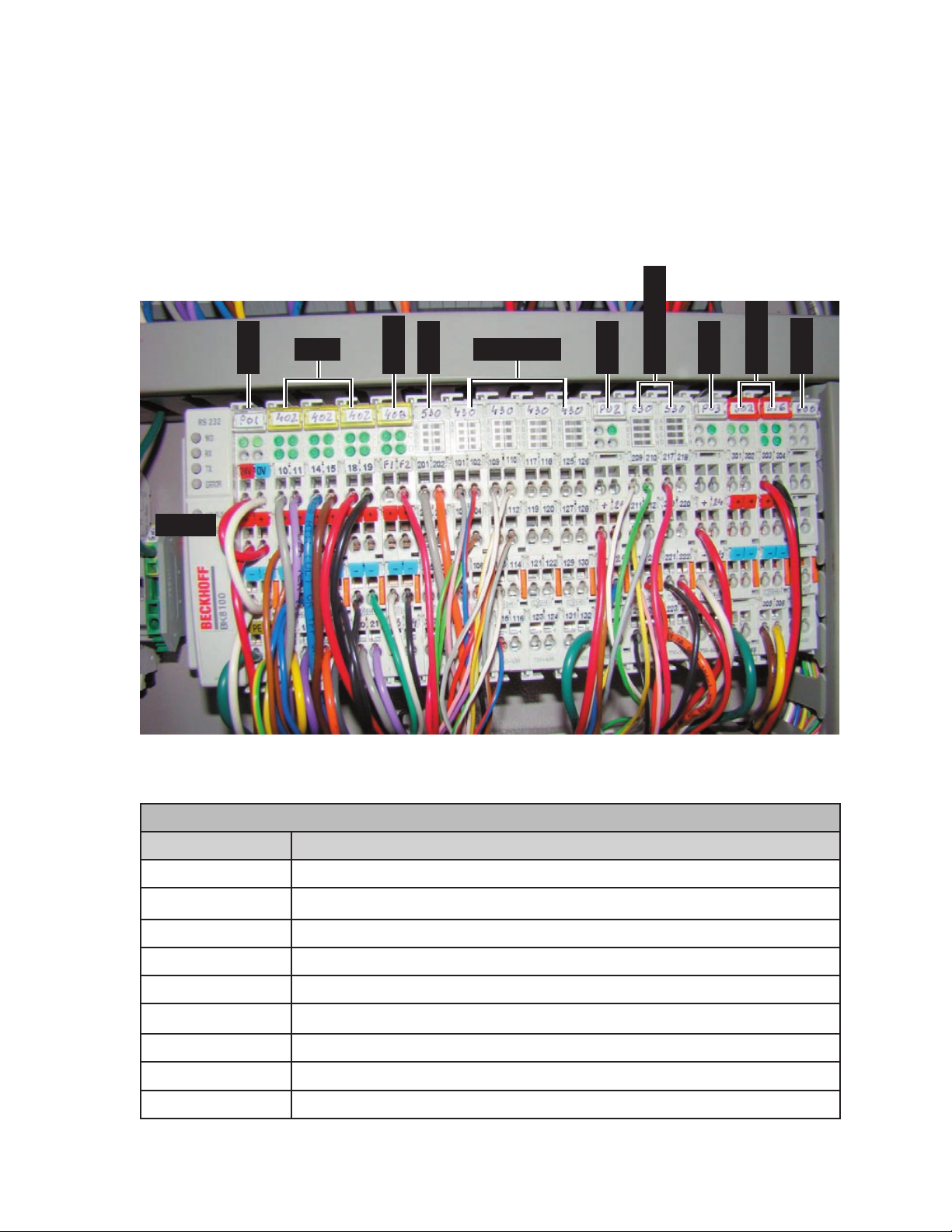
Communications and the I/O Panel
Inside the electrical panel box is the I/O control
panel. A serial cable provides communication
between the microprocessor and the I/O control
panel. Two LED’s on the communications head
of the control panel show when it is receiving
information from the microprocessor (RX) and
sending data to it (TX).
All the input signals from the sensors go
through the I/O control panel, which also powers
the sensors. When the appropriate LED on the
I/O control panel come on, it means that a signal
has been received from a sensor. Each LED is
numbered for easy identification.
Output signals from the I/O control panel go
directly to the output devices. These devices are
also powered via the I/O control panel.
Most output devices like air valves, relays, and
indicators run on the 24 VDC that comes right
from the I/O control panel. For other devices that
require a different voltage, the I/O control panel
sends an open collector output signal to drive the
logic input on a separate driver board.
When the appropriate LED on the I/O control
panel comes on, it shows that a signal has been
sent to a device. The LED on the I/O control panel
comes on to show that the panel is functioning
properly.
For open collector output, the LED means that
the I/O control panel is sending the signal to the
output device. Each LED is numbered for easy
identification.
Microprocessor
The microprocessor, located in the right
endframe (Figure 5-5) provides all of the control
logic for operating the unit.
Figure 5-5: The microprocessor unit controls all
machine operations.
Figure 5-4: CHI•Touch screen.