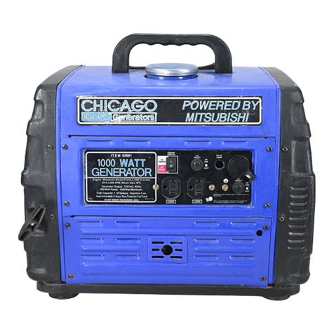
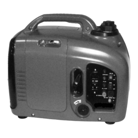
Chicago Electric 95960 User guide
Other Chicago Electric Portable Generator manuals
Chicago Electric
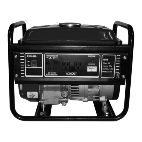
Chicago Electric 94678 and User manual
Chicago Electric
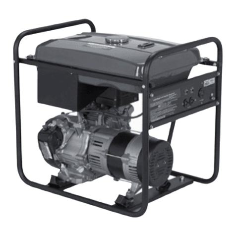
Chicago Electric 90236 User manual
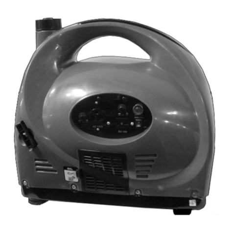
Chicago Electric
Chicago Electric 66523 User guide

Chicago Electric
Chicago Electric 98706 User guide

Chicago Electric
Chicago Electric 66619 Operation manual

Chicago Electric
Chicago Electric 65414 User guide
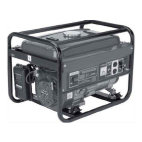
Chicago Electric
Chicago Electric 98452 User manual

Chicago Electric
Chicago Electric 95126 User manual
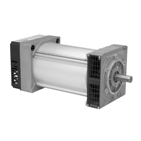
Chicago Electric
Chicago Electric 45416 Assembly and User manual

Chicago Electric
Chicago Electric 96617 Installation manual

Chicago Electric
Chicago Electric 97906 User guide
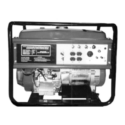
Chicago Electric
Chicago Electric 98838 User manual

Chicago Electric
Chicago Electric 91213 User manual

Chicago Electric
Chicago Electric 39321 User manual

Chicago Electric
Chicago Electric 91523 User manual

Chicago Electric
Chicago Electric 66603 User guide
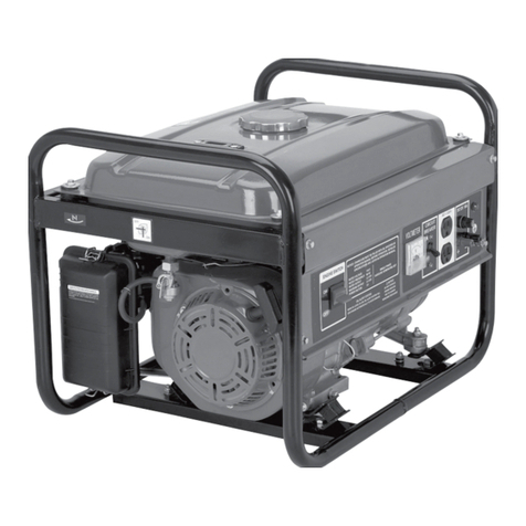
Chicago Electric
Chicago Electric 92455 User manual

Chicago Electric
Chicago Electric 94191 Parts list manual
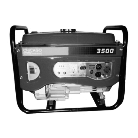
Chicago Electric
Chicago Electric 96898 Installation manual

Chicago Electric
Chicago Electric 90300 User manual


