The machine's cooling liquid contains ethylene glycol which is
harmful if swallowed and can cause redness and irritation if it
comes into contact with your eyes. Be careful when replacing
arms and electrodes.
If this machine comes into contact with water that penetrates into
its inner parts, power off the machine immediately and unplug
the power plug. Follow this same procedure whenever there is
any situation where there may be a risk of electric shock. After
an emergency, the machine may be restarted solely by trained
personnel who know which checks must be performed on the
machine.
In addition to the information provided in this paragraph, always
keep in mind the relevant prevailing regulations.
INSTALLATION
Firstly, make sure the place in which the machine is used
complies with the specifications outlined in the "SAFETY
RULES" paragraph.
On receiving the Vulcan ADU, check that the outside of the
packing is intact, otherwise report any anomalies to the person in
charge. Any damage to the packing should give rise to doubts as
far as what condition its contents might be in.
In order to handle the packing, use only a forklift or a transpallet,
paying attention to its weight and other handling instructions
reported on it.
Remove the packing and visually inspect machine integrity.
Ensure the machine has all the accessories that come with it
(page 4) as well as the optional items indicated in the compiled
and signed check-list (page 20). Promptly report any missing
parts to the supplier.
Use a suitable lifting device and straps to unload the machine
from the pallet.
All the material that makes up the packing should be disposed of
in full compliance with current environmental protection
regulations.
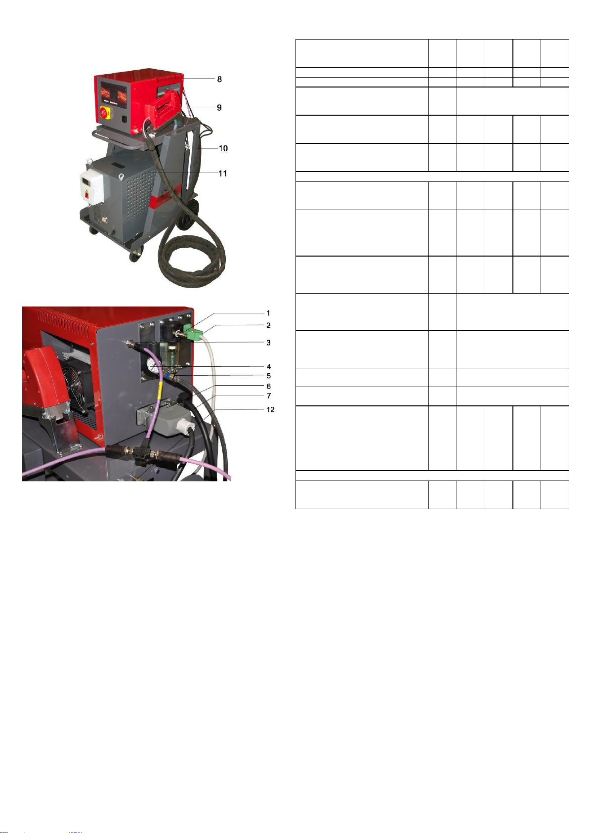
ASSEMBLY
Refer to the following instructions and directions shown in Fig. 2
(page 15) to assemble parts that are supplied disassembled.
If you purchased only the generator Item CHH5402, with lamp
included, be sure to have performed the following steps:
1. Connect the machine from an electric standpoint:
a. Connect the lamp power supply through the
appropriate ilme connector.
b. Connect the chiller power supply to the
generator.
c. Connect the CAN cable to the lamp's control
and also, where applicable, to the optional
calibrator through a "T" connection.
2. Connect the machine from a pneumatic standpoint;
3. Connect the machine from a hydraulic standpoint.
If you also purchased the chiller art. Item CHH5480, repeat steps
from 1 to 3 using the chiller in question.
If you also purchased the trolley Item CHH5404, place the chiller
and the generator above it and repeat steps from 1 to 3.
COOLING SYSTEM
In order to cool the machine adequately, it is equipped with a
chiller that maintains the water in the cooling circuit at a
temperature of 68°F. This machine cannot be used if connected
to a heat exchanger.
Fill the tank using only a mixture of water and antifreeze liquid for
car radiators. The antifreeze liquid is necessary for its anti-
corrosive properties.
Use only antifreeze liquid similar to that supplied: ethylene
glycol-based, in a concentration of about 50%, with the addition
of corrosion inhibitors.
Mix the antifreeze liquid with water in a range of 10 to 20%.
Use a higher percentage if you need to prevent the liquid from
freezing when the machine is kept in cold environments. Keep in
mind that this reduces machine performance, since increasing
glycol percentage decreases cooling efficiency.
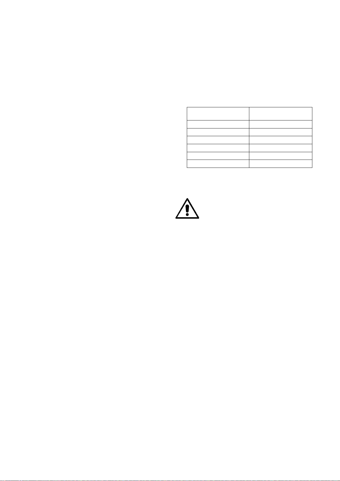
Follow the antifreeze liquid manufacturer's instructions to
determine the amount to be used, in relation to the desired
freezing temperature. The table below shows an example for the
antifreeze liquid supplied (50% of glycol).
Percentage of antifreeze
liquid with 50% of glycol
When filling and/or topping up the coolant, always be sure to use
perfectly clean liquids and containers.
ELECTRIC INSTALLATION
The installation should be carried out by
qualified personnel, aware of safety rules, who
closely adhere to the directions contained in this
manual.
The machines described in this manual are designed solely for
professional use in an industrial environment.
WARNING: the machines in question are not intended for use in
public low-voltage power lines that power buildings used for
household purposes. This can cause radio frequency
interference.
Before connecting the machine to the line, check that the mains
voltage matches that indicated on the plate. This machine was
built to be used solely at the supply voltage indicated on the
plate and is not set-up to be adjusted to other supply voltages.
Install a plug on the power cord; its required flow rate is indicated
in the technical specifications table (page 4). Figure 2 (page 13)
shows some connection examples,
It is mandatory to connect the machine to the ground wire.
Ensure the system's protective conductor is efficient and
complies with current regulations.
The technical features table (page 4) outlines supply line
requirements.
Do not use extension leads but if strictly necessary they should
be as short as possible and have a core section appropriate to
their length (indicated in the technical features table on page 4).
This machine is not designed to be powered by electricity
generating units. Using a unit of that type should be carefully
evaluated to avoid the presence of surges that could damage the
machine.