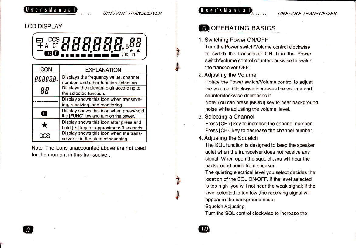
chinavasion CVSL-J71 User manual

Notices to the user
U npacking and Checking Eq ui pment --------------{
SuPPliedAccessories#
Preparation
Charging the Optional NiMh Battery Pack ----------{
lnstralling/Bemoving the Optional NiMh Battery Pac* ------€
lnstalling the Antenna #
lnstalling the Belt CliO 4
lnstalling the Hand Strap#
GettingAcquainted#
LCD Display
Operating Basics
Switciing Power ON/OFF #
AdjustingtheVolume-
SelectingaChannel #
AdlustingtheSquelch$
Placing a Call
ReceivingaCall #
Scanning
Auxiliary Function
Keypad Lock
BacklightFunction$
MonitorFunction#
Maintenance
Technical Speciffcation"#
Frequency Setting Mode #
Servicing Mode

ffi
E
E
$
$
F
I
B
I
r
t
F
fr
I
i
i
t
i
i:
ailF/yfrrFlrEt tgEVyEB
TTIANKYOT.,
We are grateful you choose for your mobile radio
applications. We believe this ease-to_use transceiver
will provide dependable communications to keep
personneloperating at peak efficiency.
transceivers incorporate the latest in advanced
technology. As a result we believe strongly that you
will be pleased with the quality and features ol this
product.
MODELS COVERED BY THIS MANUAL
5'l 18: UHF/VHF FM Transceiver
NOTICES TO THE USER
SAFETY: lt is important that the operator is
aware of and understands hazards
common to the operation of any
transceiver.
UHF/V//F TBANSCE/VER
PRECAUTIONS
Observe the following precautions to prevent fire,
personal injury and lransceiver damage.
1. The best work way recommended is that trans-
mitting lasts one minute and receiving four
minutes. Longtime transmitting or continuous
using in high power mode will cause the back
of transceiver heat. To place this transceiver,
do not let the back touch the cover of plastic
object.
2. Do not modify this transceiver for any reason.
3. Do not expose the transceiver to long periods
of direct sunlight,nor place it close to heating
appliances.
4. Do not place the transceiver in excessively
dusty, humid, and/or wet areas, nor on unstable
surfaces.
5. lf an abnormal odor or smoke is detected
coming from the transceiver, switch OFF the
power immediately and remove the optional
battery pack from the transceiver. Contact your
dealer.
. WARNING:
parked in gasoline seruie itati6nEl-

UHF/VHF TBA.V,1CE/VEB
Carefully unpack the transceiver. We recommend
that you identify the items listed in the following
table. lf any items are missing o. n"r" 0"""
damaged, please immediately .ont".t you
dealer.
/?N*
Antenna Hand strap Belt clip Screw set
UHF/VHF TBANSCE/VEB
GtnneenRAloN
1. Charging the Optional NiMh Battery pack
The optional battery pack is not charged at the
factory. Charge it before use.
lA cnurtoru
a rJo Nor RECHARGE THE BATTERY PACK tF tT tS
ALREADYpgt-1yffi
rHE LIFE OF THE BATTERY PACK TO SHORTEN OR
I I.IE BATTERY PACK MAY BE DAMAGED.
ECTtTFRm ING_
I UHNED OFF), RECHARGING WILL STAHTAGAiNTNil
THE BATTERY PACK WILL BECOME OVER CHARGED.
lnitially charging the battery pack after purchase
or extended storage (greater than 2 months) will
not bring the battery pack to its normal operating
capacity. After repeating the charge/discharge
cycle two or three times, the operating capacity
will increase to normal.
lnstalling/Removing the optional NiMh Battery
A CAUflON
.I UO NO I SHORT THE BATTERY TERMINALS OR
' NEVER ATTEMPT TO REMOVE THE CASING FROM
THE BATTEBY PACK.
!, DO NOT INSTALLIHE BATTERY PACK IN DANGEROUS
ENVTRONMENTS; SpARK MAy CAUS eXpLOSrOr.r.
pack

UHF/I/HF TRANSCE/YER
(1). lnsert the battery pack into the bottom of the
transceiver and push it until the release latch
lully locks.
(2). To remove the battery pack,press the.release
Iatc at the back of the battery pack and pull
out the battery pack.
lnstalling the Antenna
Screw the antenna into the connector on the top
of the transceiver by holding the antenna at its
base and turn it clockwise until secure.
UHF,/YHF TBANSCE/VEB
4. lnstalling the Belt CliP
lf desied, attach the belt clip using the two supplied
3X4mm screws.
5. lnstalling the Hand StraP
Loop the hand strap through the ring on the right
of the transceiver.

UHF,/VHF TBANSCE/VEB
@rNrED
1. Power switch/Volume control
Turn clockwise to switch ON the transceiver.
Rotate to adjust the volume. To switch OFF the
transcelver, turn counterclockwise fully.
UHF/I/HF TBANSCE|VEB
2. LED indicalor
Lights red while transmitting. Lights green while
receiving. lndicator becomes dark when the
battery power is low while transmitting.
3. SOL control
Turn clockwise to close the background noise.
Turn counterclockwise to open the background
noise. lt is best to adjust it to critical.
4. PTT (Push-to-Talk) switch
Press PTT key to transmit.
5. MONI (Monitor) key
Press this key to monitor weak signal.
6. SCAN key
Press this key to start or stop scanning work.
7. FUNC (Function)key
Press this key to turn on/off the LCD backight lamp.
And this key is also used for other function.
8. CH+ (Channel increase) key
Press this key to change the channel ascendingly.
9. CH- (Channel decrease ) key
Press this key to change the channel descendingly
10. Digit keypad
Set and store the frequency value and channel
number by this keypad.
11. MIC-SP jacks
Connect an optional speaker/microphone here.
a,:=\i>
a
.a
.4.-
oc)<3@
@6@@
@@@

LCD DISPLAY
UHF/VHF TRANSCE/VEB
+
a
J
UHF/VHF TRANSCE/VEB
@
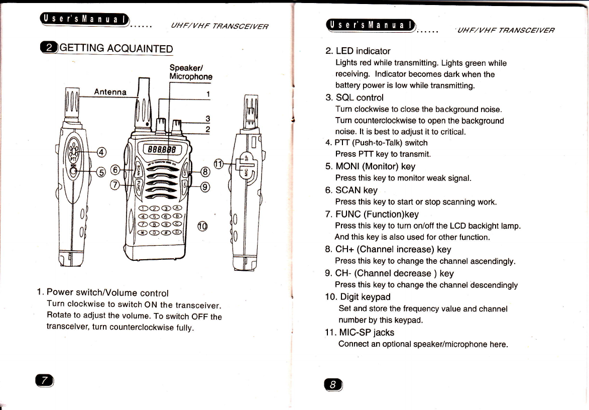
1. Switching Power ON/OFF
Turn the Power switch^y'olume control clockwise
to switch the transceiver ON. Turn the Power
switchAy'olume control counterclockwise to switch
the transceiver OFF.
2. Adjusting the Volume
Rotate the Power switchA/olume control to adjust
the volume. Clockwise increases the volume and
counterclockwise decreases it.
Note:You can press IMONI] key to hear background
noise while adjusting the volumel level.
3. Selecting a Channel
Press [CH+] key to increase the channel number.
Press [CH-] key to decrease the channel number.
4. Adjusting the Squelch
The SQL function is designed to keep the speaker
quiet when the transceiver does not receive any
signal. When open the squelch,you will hear the
background noise from speaker.
The quieting electrical level you select decides the
location of the SQL ONiOFF. lf the level selected
is too high ,you will not hear the weak signal; if the
Ievel selected is too low ,the receiving signal will
appear in the background noise.
Squelch Adjusting
Turn the SQL control clockwise to increase the
rcoN EXPLANATION
ggs.gg.g., Displays the frequency value, channel
number, and other function selection
flfl Displays the relevant digit according to
the selected function.
Display shows this icon when transmitt-
inq, receivinq ,and monitorino.
BDisplay shows this icon when press/hold
the IFUNCI kev and turn on the oower.
*Display shows this icon after press and
hold [ * ] kev for aooroximate 3 seconds.
DCS Display shows this icon when the trans-
ceiver is in the state of scanninq.
Note: The icons unaccounted above are not used
for the moment in this transceiver.
+
v
l

UHF/VHF TBANSCE/VER
quieting electrical level and close the background
noise.
Turn the SQL control counterclockwise to
decrease the quieting electrical level and open the
background noise.
Note: lt is best to adjust it to the critical condition.
5. Placing a Call
(1 ). Press the PTT key and speak into the
microphone.
O For best sound quality at the receiving station,
hold the microphone approximately 3-4cm
from your mouth and speak in your normal
speaking voice.
O The LED indicator lights red while pressing the
PTT key.
(2). Release the PTT key to receive.
6. Receiving a Call
When you receive a call on the current active
channel, th-e LED indicator lights green and you
can hear this call.
O lf the signal is weak and you also set a higher
quieting electrical level, maybe you cannot
hear this call.
q
ls
_l
UIIF/VHF TBANSCE/VER
@sqauuq
Scanning is used to monitor the signal programmed
on channels of the transceiver. The transceiver
checks each channel to find if signal appears in state
of scanning and scanning will stop on the channel on
which there is signal existing.
The transceiver will stay on this active channel until
the received signal cease. The transceiver will wait
for 5 seconds for the signal to return, otherwise
scanning resumes, except during this time it checks
and finds new signal ( for example: PTT pressing and
etc.).
Note: Scanning can be used only when at least two
channels are stored.
Press [SCAN] key to activate scan.
O Scanning begins from the current channel and
then scan upward
O Press [CH+] or [CH-] to change the scanning
order.
O The display shows'DCS'.
Press [SCAN] key or any digit key to deactivate scan.

UHF/YHF TBANSCE/YER
@
1. Keypad Lock
It is used to prevent accidental entries.
To lock the keypad, press and hold ' x 'for 3
seconds.
To unlock the keypad ,press and hold ' * 'again
for 3 seconds.
2. Backlight Function
Press [FUNC] key to light up the LCD lamp tor 5
seconds when the transceiver power is switched
on.
Press [FUNC] key again to turn off the lamp.
3. Monitor Function
This feature enables users to hear weak signals,
which is hard to be heard in state of general
operation at the press of [MONI] key And also
IMONI] key can be used to cooperate with
Volume control to adjust volume when no signal
exists on the channel selected.
Press [MONI] key to hear background noise.
Release [MONI] key to return to normal.
r
UHF/VHF TBANSCE/I/EB
@
1. General lnformaion
We have already adiusted the machine to the best
situation. ln normal it will work well with all the
functions as lhe user's manual states. Without our
permission do not adjust or change the inner
components by unprofessional person. Otherwise
the maintenance warranty will be invalid.
2. Maintenance
When the machine is sent back to the shop or
service center for maintenance, please use the
original wrapping materials to pack the transceiver
(including antenna, battery, and other accessories)
into the primary box. and write a detail report of the
trouble with your name, address, telephone number
and fax (if possible). Do not only send back the
components of the machine, please send back the
integrated transceiver.

UHF/VHF TBANSCE|VEB
BAND UHF
T51 18 35O-370MHz
Range T51 18(1) 4oo-42OMHZ
T51 18(2) 450-470MHz
Power Output 2.5W
lhannel Number 100
lommunication Range 5-15km(on broad area)
Audio Distortion <5%
Frsquency Stability Sppm
\rd .Freq. Deviation < t 5KHz
)purious Radiation Better than 6OdB
\djacent-channel Po$/er Betterlhen 60dB
iensitivity Befter than 0.2oUV
;quelch Sensitivity Betterthan 0.1 sljv
\diacent-channel Selectiviiy Better than 60dB
)purious Response Reiection Better then 60dB
ntermodulation Rejection Better then 60dB
Itandby Current 40mA (lt is about't5mA in state ol power sve)
Transmittino Current 1.24
lperation Voltage 6.0v
UHF/I/HF TBANSCE/VER
ln this mode you can enler desired frequency into
channals within the allowable frequency range and
you can store maximum 100 channels.
Example: Assuming the transceiver is on CH-Ol and current lrequency
on CH-01 is 450.175MH2 before switched off. Now you want to set up
450.250MH2 as receiving lrequency and 450.750MH2 as transmitting
frequency on this channel.
STEP OPERATION DISPLAY
Step 1
Press and hold [FUNC] key
and turn the Power switch/
Volume control clockwise to
switch the transceiver ON.
Step 2
Now it is in the
state of setting
receiving freq-
uenycy. Please
enter'4', '5', '0',
'2" '5" 'O', in
turm A short
tone will be
heard when
you press the
key each time.
Enter'4' u.. -.. cll
e' *'l
Enter'5' .Y5-.---91
Enter'0' "Y50- - - "9.1
Enter'2' .Y58.e-- "q.il
Enter'5'
Enter'0' .q50.e58 9.!]
Step 3Press PTT key and a lwo tone
beep sounds. The receiving freq-
uency value you put into will be
stored into the channel shown
currently.
Note: lf vou want to set same transmittino freouencv as reeivino
frequency, you do not need to follow thelollot/i,ino steD4. 5. 6. -
Press IFUNC] key to switch to
settino transmittino freouencv
mode.-The display s'hows "+' anil
the receiving Irequency value on
current channel.

UHF/VHF TEAA|SCE|VEB
Step 5
Now it is in the
state of setting
transmitting
frequenycy.
Please enier'4',
'5"'0"'7" '5" ',o',
in turm A short
tone will be
heard when
you press the
key each time.
Enter'4'
Enter'5' *.Y5. 0ll
-')
Enter'0' '.Y50---.g.I
Enter'7' . .950?- - .9.J]
Enter'5' . .Y50?5- .,.]
Enter'0' . .Y50?50.9.JJ
Step 6
Press PTT key and a two tone
beep sounds. The transmitling
frequency value you put into will
be sored inlo the channel shown
currenllv-
It you want to delete current channel,
press ISCAN] key. " " " 0t
a
lI you want to change the storing
channel, pless press [CH+] or [CH-].
Example:press [CH+] and CH-02 is
clear.
UHF/VHF TBANSCE|YEB
fll) senvtctNc MoDE
STEP OPEHATION DISPLAY
Step 1
Press and hdd
ISCANI key and
turn the Power
switch/Volume
control cloc,kwise
to switch the
transceiver ON
lf the trequ-
ency sel
previo u sly
is 45O.375M
lf the mode
hasn't been
used belore.
Step 2
Enter your desi-
red frequency.
Example: put
into 450.250MH2
by enter '4', '5',
'0" '2" '5" ',o' in
turn.A short tone
will be heard
when you press
the key each
time.
Enter'4'
Enter'5' q5-
Enter'0' Y58-
Enter'2' Y58t-
Enter'5' \iars-]l
Enter'0' I Yssrtt-l
Step 3After you enter 6 digils, you
can test all receiving and
transmiting specif ications
under this lreguency.
Table of contents
Other chinavasion Transceiver manuals
Popular Transceiver manuals by other brands

Phoenix Contact
Phoenix Contact RAD-ISM-900-DATA-BD quick start guide

Vertex Standard
Vertex Standard VX-350 series operating manual

BWI Eagle
BWI Eagle AIR-EAGLE XLT Product information bulletin

Kenwood
Kenwood TK-3170 Service manual

Yaesu
Yaesu FT-840 Service manual

Vertex Standard
Vertex Standard VX-424A Service manual

Kenwood
Kenwood TK-2200 Service manual

Standard Horizon
Standard Horizon ECLIPSE + GX1250SA Service manual

Sailor
Sailor VHF 5000 Series Workshop manual

Intel
Intel Arria 10 series user guide

Delta Electronics
Delta Electronics LCP-200A4HSR Specifications

Hallicrafters
Hallicrafters SR-160 Operating and service instructions