CHIOSSI E CAVAZZUTI ACE 950 Instruction sheet

Chiossi e Cavazzuti s.r.l.
Via Costituzione 50/D - 4201 5 Correggio (RE) Italy
Tel: +39 0522 637224 - Email: cc@chiossiecavazzuti.com
www.chiossiecavazzuti.com
Designed and Manufactured 1 00% in Italy
INSTALLATION GUIDELINE
Rev: 05_2020
Model: ACE 950 - DUAL 1200

PRE INSTA ATION CHECK IST
Follow these steps to successfully install the dryer:
1 ) VERIFY DOORS, BUI DING AND MACHINE DIMENSIONS
2) VERIFY WEIGHT AND EQUIPMENT FOR HAND ING (forklift needed)
3) VERIFIY EXHAUST CONNECTION (technician needed)
4) VERIFY E ECTRICA REQUIREMENT (electrician needed)
Each step of the installation is described in depth in this document.

TABLE OF CONTENTS
1. INTRODUCTION 4
1 .1 About this document 4
1 .2 Purpose and target group 4
1 .3 Equipment required 5
2. SHIPPING AND HANDLING 6
2.1 Packaging 6
2.2 Dimensions 6
2.3 Weight 6
2.4 ifting and handling 7
2.5 Forks placement 7
3. DIMENSIONS 8
4. EXHAUST PIPELINE REQUIREMENTS 10
4.1 Exhaust connection 1 0
5. ELECTRICAL REQUIREMENTS 11
5.1 Electrical connection 11
6. INSTALLATION 12
6.1 Unpack the Dryer 1 2
6.2 Connect the Inlet and Outlet to the Tunnel 1 3
6.3 Electrical connection 1 5
6.4 Belt conveyor 1 7

1. INTRODUCTION
IMPORTANT
READ CAREFULLY BEFORE USE
KEEP FOR FUTURE REFERENCE
1.1 ABOUT THIS DOCUMENT
• Make sure that this document is accessible at all times.
• The manufacturer does not provide warranties of any kind with regard to this manual. The data in
this document were valid at the time of publication and may change without notice. The latest
technical developments are constantly being incorporated into our documentation. Therefore
illustrations and descriptions are subject to modification.
• Use of this manual takes place under the full responsibility of the user. The manufacturer shall not be
held responsible for any errors contained within this document, nor for any accidental damage
resulting from the supply or use of this manual.
• This document contains proprietary information. All rights reserved.
1.2 PURPOSE AND TARGET GROUP
This document is part of the machine documentation and contains information about the site and
enviroment conditions and requirements for a safe and successful commissioning and installation of
the Dryer.
This document must be handed out to the customer prior to the installation.
The information of this document should be referred to the following personnel:
• Customers and trained customer technicians
• General service technicians (Distributor service technicians)
• Chiossi e Cavazzuti service technicians

1. INTRODUCTION
1.3 EQUIPMENT REQUIRED
To properly install and maintain TETRIS dryer you will need this equipment in
advance:
- cordless screwdriver/drill
- Phillips bit PH1
- Phillips bit PH2
- flat-blade screwdrivers
- Phillips screwdrivers n ° 1 -2
- adjustable spanner wrench
- fork spanner set 7-8-1 0-1 3-1 7-1 9-24-30
- tube spanner set 7-8-1 0
- allen key set up to 1 0
- universal pliers
- clamp for tube housings up to 25mmq
- cutter
- spirit level
- ac / dc multimeter
- current clamp
- thermometer with wired probe

2.1 PACKAGING
• The machine is delivered inside a wooden cage over a pallet, closed on all sides.
• The machine is always covered with a heat shrinkable plastic sheet.
• If the transport is carried out by ship, the machine will be protected by a heavy-duty barrier bag.
In addition salt minerals will be placed inside the packaging to minimize moisture exposure.
• The machine is attached to the pallet on several points. Some parts of the machine have been
disassembled prior to shipment in order to avoid accidental damage and reduce overall space
(indicator light, casters, inlet and outlet, etc). Refer to the Installation chapter for detailed instructions.
PACKING LIST
Dryer weight and overall size of the wooden cages and pallets are listed in the table below.
Note that the dryers are assembled when delivered inside the wooden cage. When delivered on
pallet, inlet/outlet and belt conveyor are detached in a separate pallet.
2.2 DRYER OVERALL SIZE
• For detailed dimension of the machines refer to the drawings at page 8.
2.3 WEIGHT
• All values are excluding packaging parts.
2. SHIPPING AND HANDLING
CONTENT GROSS WEIGHT
750 kg
ACE 950 - 1 390066
CAGE EXTERNAL SIZE
4500 x 1 470 x 2200 mm
DRYER MODEL NET WEIGHT
ACE 950 - 1 390062 650 kg
DRYER MODEL DRYER DIMENSIONS [LxWxH]
ACE 950 - 1 390066 3800 x 1 250 x h21 63
11 00 kg
IN ET/OU ET EXTENSIONS 1 500 x 750 mm
11 00 kg
DUA 1 200 - 1 390052 4400 x 1 780 x 2200 mm
DUA 1 200 - 1 390052 780 kg
DUA 1 200 - 1 390052 41 00 x 1 500 x h21 63
CONTENT GROSS WEIGHT
750 kg
ACE 950 - 1 390066
PALLET SIZE
2250 x 1 300 mm
11 00 kg
DUA 1 200 - 1 390052 2250 x 1 600 mm

2. SHIPPING AND HANDLING
2.4 LIFTING AND HANDLING
• All necessary equipment to move the machine must be supplied by the customer.
• The lifting must be carried out with forklift. Do not use transpallets or hydraulic platforms.
• To handle the machine with any type of crane please contact Chiossi e Cavazzuti technical service
since special equipment and instructions are needed.
2.5 FORKS PLACEMENT
• The machine must be lifted only from the lateral side.
1 ) Spread the forks wide open and align them to the horizontal bars of the frame.
2) Verify that the edge of the forks exit on the other side of the dryer.
3) Always check the overall balance of the machine when moving the machine.
PARAMETER VALUE

3. DRAWING - ACE 950

3. DRAWING - DUAL 1200

4. EXHAUST REQUIREMENT
4.1 EXHAUST CONNECTION
• The exhaust pipeline installation must be carried out by an authorized local technician (mandatory).
• Exhaust tubes and pipes are not supplied with the machine and must be organized by the customer.
• Connect the exhaust pipeline to the outside. Thermo-insulation of the exhaust pipes is
recommended.
• The maximum length of the pipeline is 1 0 meters. For longer piping it is necessary to increase the
diameter of the pipe or install a suitable aspirator.
• imit the number of curves and horizontal sections. Curved tubes must have a max. angle of 45 °.
• The exhaust extractor fan for the dryer is built inside the machine.
• An oily liquid will form in the ducting from the condensation of the vapors. It is necessary to seal all
joints with special oil-resistant silicone, and ensure that the path of the pipes does not overhang an
area where falling drops can cause damage.
PARAMETER VALUE
1 80 m3/h
1 50 mm
(max 1 0 meters with 2 curves; for longer lengths
or twisty pipeline, increase the diameter)
Top of the machine.
Flange is delivered with the machine
Galvanized Iron
Exhaust flow rate
Connection diameter
ocation of the connection
Material type

5.1 ELECTRICAL CONNECTION
• The Manufactuer does not provide the power cord or plug. All the needed cables and connection
parts must be supplied by the customer. All power cords must match the national electrical safety
regulations.
• Use 4 core cable (3Ph+Pe) of an adequate cross-section and connect to a thermal magnetic switch
protected by a 30mA Residual Current Device (RCD).
• The connection to the main power must be carried out by an authorized local electrician (mandatory).
• The electrician responsible of the connection must verify that the power plant conditions match the
national electrical safety regulations and are suitable for the machine requirements.
• The machine is built for fixed main connection only. The power cords must enter the electrical
cabinet from the top.
5. ELECTRICAL REQUIRMENT
ELECTRICAL DATA ACE 950 - 1390066
3P + PE
208 ± 1 0%
50 Hz
1 4 kW
Phases
Voltage [V]
Frequency [Hz]
Max Consumption [kW]
42 A
Current [A]
DUAL 1200 - 1390052
3P + PE
208 ± 1 0%
50 Hz
1 9 kW
50 A

6. INSTALLATION
6.1 UNPACK THE DRYER
• The machine is attached to the pallet on several
points. Some parts of the machine have been
disassembled prior to shipment in order to avoid
accidental damage and reduce overall space
(indicator light, casters, inlet and outlet, etc).
Note that the dryers are fully assembled when
delivered inside the wooden cage. When delivered
on pallet, inlet/outlet and belt conveyor are detached
in a separate pallet.
• After the unloading operation, free all parts from the packaging. The tunnel and inlet/outlet are fixed
on the pallet with screws. All the auxillary parts (screws, belt conveyor, exhaust tube flage, etc..) are
placed inside the tunnel of each corresponding machine.
• Place the tunnel in the desired position. Unlock
the hoock on top of the roof to open all lateral
panels.
• evel the tunnel, check the 4 sides of the chassis
and regulate the adjustable feet accordingly. If
levelling is not successful, the conveyor belt will not
remain alligned correctly.

6.2 CONNECT THE INLET AND
THE OUTLET TO THE TUNNEL
• At first remove the squared metal plates in every
corner of the tunnel (4 total). The belt conveyor is
on moving railings, these plates are firmly screwed
to avoid accidental moving of the belt conveyor
lifting system.
• Do not dispose the plates. After the inlet and the
outlet have been connected, these plates will be
eventually screwed in the same position again.
CONNECT THE INLET
• Identify the inlet by the label, usually it's longer
and heavier than the oulet.
• To lift the inlet in position secure it to a suitable
forklift with anchor straps in the corners.
Alternatively 3 or more Operators are needed to
manually lift the structure.
• Align the inlet to the plates of the tunnel as shown
in the picture.
• Insert 6 screws from the inside to attach the
plates for each side. Do not tight completely yet in
order to suspend the structure and be able to level
it.
• 2 or more operators are needed to level the
structure, one adjust the height and tilt of the inlet
while the other tigthen the screws to fix it in
position, refer to the picture. Measure the level on
both sides and on the roller of the belt.
6. INSTALLATION

• When the roller and all sides and of the inlet are leveled,
firmly tight all screws with nuts to secure it in place.
The screw highligthed in green in the side picture is
needed to secure the lower metal sheet.
Place all the nuts in the closed side of the inlet.
• Insert again the square metal plate on both sides. Insert
the long screw and the washer from the inside of the
tunnel. The second whasher stays between the frame and
the inlet as a spacer while the sware plate and nut are on
the other side of the inlet. Refer to image.
Do not tighten the plate in order to be able to raise or
lower the belt conveyor system with the handwheel.
CONNECT THE OUTLET
Follow the same instruction as for the inlet. The outlet
should be easier since it is smaller and lighter.
6. INSTALLATION

6.3 ELECTRICAL CONNECTION
IN ET
• Insert the cable duct in the lower part of the inlet through the holes. Secure the cables with the quick
joint connection.
• Identify the terminal block X3: refer to the numbers of
the wires and plug in accordingly.
• Insert a small flat screwdriver and tilt it slightly to open
the connector. Plug in the wire, remove the screwdriver
and try to pull out the wire to verify the hold of the
connection.
• Double check that all the wires are coupled correctly.
WIRE SEQUENCE FROM ABOVE
LEFT BLOCK:
26 RED
25 B ACK
40 BROWN
41 B UE
42 WHITE
RIGHT BLOCK:
26 RED
25 B ACK
40 BROWN
41 B UE
6. INSTALLATION

6.3 ELECTRICAL CONNECTION
OUT ET
• Insert the cable duct in the lower part of the inlet
through the holes. Secure the cables with the quick
joint connection.
• Identify the terminal block of belt motor M3: refer
to the numbers of the wires and plug in accordingly.
• Double check that all the wires are coupled
correctly.
WIRE SEQUENCE FROM ABOVE
FEEDING MOTOR M3:
40 BROWN
41 B UE
FEEDING BELT CENTERING DEVICE:
25 B ACK
6. INSTALLATION

6.4 BELT CONVEYOR
• The belt conveyor must pass above every tube, both lower and upper tubes, refer to pictures below.
• Use a board or a flat surface as a working table and bring the joints of the belt conveyor close to
each other.
•
6. INSTALLATION

• Align the edges of the belt and insert the provived
thread.
• Be careful to joint the belt in the correct position
without losing any hooks. The edge must be flat
and without any indent.
• Finally fold inside the thread to secure the closure.
6. INSTALLATION
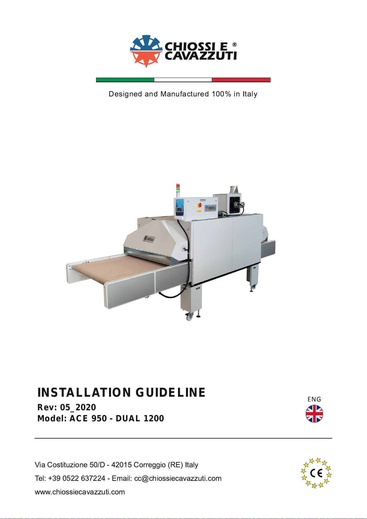
This manual suits for next models
3
Table of contents
Other CHIOSSI E CAVAZZUTI Dryer manuals
Popular Dryer manuals by other brands

Maytag
Maytag MGDB980BW0 installation instructions

Bosch
Bosch WTB86201ID Installation and operating instructions

Bobrick
Bobrick TrimLineSeries Technical data

Whirlpool
Whirlpool ELECTRIC DRYER installation instructions

Tesla
Tesla WT8H90MS user manual

Bosch
Bosch WTW87F90CH Installation and operating instructions