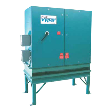
ChipBLASTER STANDARD UNIT D30-80-1 Setup guide

P/N: MAN-D3001
ChipBLASTER, Inc.
D30-80-1
FIXED VOLUME MODELS
HIGH PRESSURE / HIGH VOLUME COOLANT DELIVERY SYSTEM
STANDARD AND
CERTIFIED
STATEMENT NUMBER 00-10-005
INSTALLATION, OPERATION and SERVICE
MANUAL
ChipBLASTER, Inc.
13605 South Mosiertown Road
Meadville, PA 16335
USA
www.chipblaster.com
Telephone 814-724-6278
Fax 814-724-6287
For your records please list serial number from nameplate ______________ REV K

ChipBLASTER Inc
2
REVISION RECORD
REVISION DATE PERSON DESCRIPTION OF CHANGE
A 02 MAR 2006 WPA NEW RELEASE
B 17MAR06 JRG ADDED MORI CABLES
C 31 MAR 2006 WPA DWG REV SECT 21.0.
D 5 APR. 06 R.B. DWG. REV. PAGE 42
E 19 MAY 2006 R.B. ADDED PAGE 25 (CHECKING
OIL USING SIGHT GAUGE)
F 10 JULY 2006 RRW ADDED DAEWOO INTERFACE
G 8 JAN. 2007 R.B. REVISED SHIP LOOSE ITEMS
PAGE 59.
H 18JUN07 JRG ADDED KIWA CABLE
J 21JUN07 JRG ADDED LOW PRESSURE
OPTION
K 11JAN08 TD ADDED AIR PURGE
PROCEDURE

ChipBLASTER Inc
3
GENERAL:
This manual covers the following ChipBLASTER model:
D30-80-1 - STANDARD UNIT (60Hz)
For the model number of your unit refer to the data nameplate located on
the enclosure door.
DATA NAME PLATE
UNIT MODEL NUMBER UNIT SERIAL NUMBER

ChipBLASTER Inc
4
GENERAL:
This manual covers the following ChipBLASTER model:
D30-80-1 - CE CERTIFIED UNIT (50Hz)
For the model number of your unit refer to the data nameplate located on
the enclosure door.
DATA NAME PLATE
UNIT MODEL NUMBER
UNIT SERIAL NUMBER

ChipBLASTER Inc
5
1.0. GENERAL WARNINGS:
Thank you for purchasing a ChipBLASTER high-pressure coolant system.
For reliable, safe and long term operation of your ChipBLASTER:
Machine must be installed and connected to electric service per the installation
portion of this manual.
All persons who will be operating and maintaining this machine must read and
understand this manual.
DO NOT AT ANY TIME USE FLAMMABLE OR EXPLOSIVE FLUIDS IN OR
NEAR MACHINE.
DO NOT STAND ON MOTORS, SUPPORTS, or JUNCTION BOXES WHILE
WORKING ON THE ChipBLASTER.
REFER TO SECTION 4.1. FOR EXPLANATION OF MARKINGS
1.0

ChipBLASTER Inc
6
2.0. Table of Contents:
General (Standard Unit) Page 3
General (CE Certified Unit) Page 4
General warnings Section 1.0 Page 5
Table of contents Section 2.0 Page 6
Specifications Section 3.0 Page 8
Safety precautions Section 4.0 Page 9
Explanation of markings Section 4.1 Page 9
Storage Section 5.0 Page 14
Moving machine Section 6.0 Page 14
Placing a ChipBLASTER Section 7.0 Page 15
Mechanical installation Section 8.0 Page 16
Electrical installation Section 9.0 Page 17
Power Interface Section 9.1 Page 17
Control Interface Section 9.2 Page 17
Start up Section 10.0 Page 18
Air Purge Procedure Section 11.0 Page 19
Operation Section 12.0 Page 20
Electrical operation Section 12.1 Page 20
Coolant flow Section 12.2 Page 20
Coolant flow Diagram (Figure 1) Section 12.2 Page 21
Alarms Section 13.0 Page 22
Preventive maintenance Section 14.0 Page 22
Schedule (Figure 2) Section 14.1 Page 23
High pressure pump – Check oil - Dipstick Section 14.2 Page 24
High pressure pump – Check oil – Sight gauge
Section 14.2 Page 25
High-pressure pump –
Oil change procedure Section 14.3 Page 26
High pressure pump – Check belt Section 14.4 Page 29
High-pressure pump – Check for leaks Section 14.5 Page 29
High-pressure pump – Rebuild Section 14.6 Page 29
Return (Transfer) Pump – Check for leaks Section 14.9 Page 29
Cartridge filter – Check pressure gauge Section 14.12 Page 29
Filter change procedure – General Warnings Section 14.13 Page 30
Dual manual change filter (shutdown) Section 14.14 Page 30
Dual manual change filter (operating) Section 14.15 Page 31
Filter Replacement form Section 14.16 Page 32
Filter assemblies – Check for leaks Section 14.17 Page 33
Filter assemblies – Cleaning Section 14.18 Page 33
Pump mounting bolts – Check Section 14.27 Page 33
Return pump - Check flow rate Section 14.29 Page 33

ChipBLASTER Inc
7
2.0. Table of Contents (Cont.):
Return pump - Check for leaks Section 14.30 Page 33
Return pump - Check inlet and outlet Section 14.31 Page 33
Troubleshooting Section 15.0 Page 34
Troubleshooting flow chart (Figure 3) Section 15.1 Page 35
Pressure adjustment procedure Section 16.0 Page 36
High pressure pump replacement Section 17.0 Page 37
Belt installation Section 18.0 Page 38
Deflection force chart Section 18.5 Page 40
System contamination purging procedure Section 19.0 Page 41
Electrical drawings Section 20.0 Page 43
Mori Seiki Power Interface Section 20.0 Page 51
Mori Seiki Control Interface Section 20.0 Page 52
Daewoo/Doosan Interface Section 20.0 Page 53
Kiwa Interface Section 20.0 Page 54
Schematic piping drawing Section 21.0 Page 59
Mechanical assembly Section 22.0 Page 60
Gauge Panel – Top Section 22.1 Page 60
Control Panel – Front Section 22.2 Page 61
Control Panel – Inside Enclosure Section 22.3 Page 62
Sub Plate Elevation – Left Side Section 22.4 Page 63
Sub Plate Elevation – Right Side Section 22.5 Page 64
Manifold block assembly Section 22.6 Page 65
Filter Assembly Section 22.7 Page 66
Ship Loose Items Section 22.8 Page 67
Spare Parts Section 22.13 Page 68
Footprint drawing Section 23.0 Page 69
Warranty Section 24.0 Page 70
Warranty (limited) – New equipment Section 24.1 Page 70
Warranty (limited) – Used equipment Section 24.2 Page 72
Warranty (limited) – Retrofits Section 24.3 Page 74
Warranty claim form Section 24.4 Page 76
Warranty registration card Section 24.5 Page 77
Warranty validation card Section 24.6 Page 78
Optional Equipment Section 27.0 Page 79
Machine Sump Standpipe Assembly Section 27.1 Page 79
Supplement Data Section 28.0 Page 80
1000 PSI orifice chart Section 28.1 Page 80
2.0

ChipBLASTER Inc
8
3.0. SPECIFICATIONS:
FCC REGULATIONS:
This device complies with Part 15 of the FCC Rules. Operation is subject to the following two
conditions: (1) This device may not cause harmful interference, and (2) this device must accept
any interference received, including interference that may cause undesired operation.
**All specifications, instruction, pictures, and illustrations in this manual are believed to be
accurate and may contain ChipBLASTER Inc. proprietary information, which is privileged,
confidential, or subject to copyright / patent belonging to ChipBLASTER Inc.. This manual is
intended for the operation and maintenance of your ChipBLASTER unit. You are hereby notified
that any dissemination, distribution, copying, or action taken in regard to the content of this
manual is strictly prohibited and may be unlawful. ChipBLASTER Inc. also reserves the right to
change the contents of this manual without notice. If you have any questions please contact
ChipBLASTER Inc. at (814) 724-6278.
3.0

ChipBLASTER Inc
9
4.0. SAFETY PRECAUTIONS:
The items described in these instructions are very important, so that you can use
the ChipBLASTER safely, prevent injury to yourself and other people around you as well
as prevent damage to property in the area. Thoroughly familiarize yourself with the
symbols and indications shown below and then continue to read the manual. Make sure
that you observe all warnings given.
4.1. EXPLANATION of MARKINGS:
Symbols Meaning of Symbols
DANGER
Indicates that error in operation may lead to death or serious injury.
WARNING
Indicates that error in operation may lead to injury (*1) to people or that
these errors may cause damage to physical property. (*2)
*(1) Such things as injury, burns or shock that will require
hospitalization or long periods of outpatient treatment.
*(2) Physical property damage refers to wide-ranging damage to
assets and materials.
Prohibited
Indicates prohibition (Don’t do it).
What is prohibited will be described in or near the symbol in either text
or picture form.
!
4.0-4.1

ChipBLASTER Inc
10
4.1. EXPLANATION of MARKINGS (Cont.):
Symbols (Cont.) Meaning of Symbols
Mandatory
Indicates something mandatory (must be done).
What is mandatory will be described in or near the symbol in either text or
picture form.
PINCH POINT
Any point where lids or covers may pinch fingers.
Exercise caution when closing lids or covers. (Oil skimmer cover).
CUTTING HAZARD
Any point where exposed fan blades may cause a cutting hazard to fingers
when guard or inlet hose is not in place. Do not operate without guard or
inlet hose in place. (Inlet to MistBLASTER).
PINCH POINT
Any point where fingers may be pinched by the motion of a belt.
Do not operate with guard or cover open. (Oil skimmer).
LIFTING HAZARD
Use caution when lifting filter bags from filter housing. Bags may be
heavy depending on the material being machined.
!
4.1

ChipBLASTER Inc
11
4.1. EXPLANATION of MARKINGS (Cont.):
Symbols
Meaning of Symbols
ELECTRICAL SHOCK HAZARD
Shut off main disconnect before opening any electrical enclosures or
junction boxes. UNITS WITH ADJUSTABLE FREQUENCY
DRIVES: BEFORE PERFORMING ANY WORK, BE AWARE
THAT A DRIVE WILL HOLD A LETAL CHARGE FOR A
MINIMUN OF 10 MINUTES.
LOCK OUT ELECTRICAL POWER
Lock out and tag any and all disconnect switches before performing any
maintenance work on equipment.
SAFETY GLASSES REQUIRED
When removing filter bags or working on equipment, safety glasses must
be worn to prevent injury from splashing fluid or from other hazards.
MACHINE STARTS AUTOMATICALLY
ChipBLASTER equipment will start without operator input. Do not
remove any guards or covers until disconnect switches are shut off, locked
out and tagged.
UNPLUG SOURCE OF ENERGY
Before performing any work on items, such as the oil skimmer, unplug the
unit.
4.1

ChipBLASTER Inc
12
4.1. EXPLANATION of MARKINGS (Cont.):
Symbols (Cont.) Meaning of Symbols (Cont.)
NO ACCESS FOR UNAUTHORIZED PERSONS
Do not open electrical enclosures or remove any guards if you have not
been trained or do not have knowledge of the equipment.
FORK TRUCK LIFTING POINT
To transport equipment, forks of truck must be located between points
indicated so that mechanical damage to machine will not result.
SAFE OPERATING PRESSURE
Safe operating pressure will be listed below symbol in PSIG and Bar.
Do not operate above stated pressures as equipment damage or personal
injury will result.
DO NOT STEP OR STAND ON
Do not use surface as a step or platform when servicing equipment.
Motors and electrical boxes are not designed to be used as steps or
platforms and injury may result from falls.
READ THE TECHNICAL MANUAL
Before attempting to work on or repair this machine read and understand
this manual. If certain procedures are not followed, mechanical and or
personal injury will result.
4.1

ChipBLASTER Inc
13
4.1. EXPLANATION of MARKINGS (Cont.):
Symbols (Cont.) Meaning of Symbols (Cont.)
WEAR SAFETY GLOVES
When changing filter bags it is recommended to wear safety gloves to
protect hands from metal chips and the coolant that may be used in the
machine.
DO NOT OPERATE WITH GUARD REMOVED
Do not operate machine with guards removed as hazards to personnel will
be present and injury to personnel could result.
LIFTING POINT
Machine must only be lifted at points indicated in order to avoid
mechanical damage and personal injury. Lifting slings or chain slings
must be adequately sized to carry the weight of the MistBLASTER.
Refer to MistBLASTER footprint drawing for actual weight.
BURN HAZARD HOT SURFACE
Surface of transformer will become hot after extended periods of
operation. Do not set anything on transformer or restrict airflow around
transformer. DO NOT TOUCH.
4.1

ChipBLASTER Inc
14
5.0. STORAGE:
If the ChipBLASTER is to be stored for any period of time it must be keep in an area that is protected
from freezing. Freezing temperatures will damage the pumps and the valves. Keep ChipBLASTER
covered until ready to move to site. If MistBLASTER is also supplied keep covered.
6.0. MOVING MACHINE:
When moving the ChipBLASTER to the final site the following must be adhered to:
Lift ChipBLASTER only from the sides adjacent to the electrical enclosure.
Forks must extend the full distance under ChipBLASTER. The fork truck lifting capacity must be
sufficent to safely lift the ChipBLASTER without tiping. Refer to footprint drawing (Section 23) for
machine dry weight.
MOVE SLOWLY AS NOT TO DROP THE ChipBLASTER.
DO NOT TRY TO MOVE ChipBLASTER WITH FLUID IN FILTERS.
DO NOT STAND UNDER ChipBLASTER AT ANY TIME.
If MistBLASTER is supplied with ChipBLASTER:
When lifting or moving the MistBLASTER, lift only at the eyebolts provided on the top.
Sling must be of sufficent capacity to safely lift the MistBLASTER.
DO NOT STAND UNDER MistBLASTER AT ANY TIME.
!
!
!
!
!
5.0-6.0
!

ChipBLASTER Inc
15
7.0. PLACING A ChipBLASTER:
7.1. After you receive your new ChipBLASTER unit the first thing you need
to do is prepare the site where you would like to place the unit.
INSTALLATION SITE MUST BE FLAT AND LEVEL.
7.1.1. You need to keep the unit within 3M (10’) of the machining center that you are
conncecting the ChipBLASTER to.
7.1.2. Locate the unit so the ChipBLASTER’s electrical cabinet is within 3M (10’) of
the machining center’s electrical cabinet.
7.1.3. Make sure you place the unit so maintenance can easily get to the filter housings
and electrical cabinet on the ChipBLASTER unit. Refer to footprint drawing
(Section 23) for recommended clearances.
7.2. After you have the site cleared for the ChipBLASTER unit you are
ready to prepare the ChipBLASTER.
7.2.1. Remove the lumber that is used to hold the unit in place during transporation
using a phillips screw driver or an electric screw gun.
7.2.2. Before you remove the ChipBLASTER from the skid take a moment to locate the
bags containing the casters.
7.2.3. When removing the ChipBLASTER from the skid, lift unit from the sides only!
Insure the forks extend completely under the ChipBLASTER unit.
DO NOT AT ANY TIME REACH UNDER THE ChipBLASTER UNIT
OR STAND UNDER THE ChipBLASTER UNIT WHILE IT IS
SUPPORTED BY A FORK TRUCK. IF YOU MUST REACH UNDER
THE MACHINE BLOCK IT UP FOR SAFETY.
7.2.5. After you remove the ChipBLASTER from the skid take the set of four casters
and mount them in the receptacles located at each corner of the ChipBLASTER
unit. As a safety precaution, block unit while installing casters. Note: Two
casters are rigid and two swivel. Locate both swiveling casters on same end of
unit.
7.2.6. After you have the casters in place, move the ChipBLASTER into desired
location.
!
!
7.0

ChipBLASTER Inc
16
7.0. PLACING A ChipBLASTER (Cont.):
After ChipBLASTER is in place and level, locate all ship loose items. Ship loose items
include: high pressure hose with adapter fitting, low pressure hose and low pressure hose
clamps. Place all hoses at the front of the unit (same end as enclosure).
7.2.7. After locating all ship loose items, you are now ready to either contact
ChipBLASTER, Inc. to schedule installation or proceed yourself depending on
your agreement.
POWER FOR ChipBLASTER MUST BE AVAILABLE BEFORE
SCHEDULING INSTALLATION.
8.0. MECHANICAL INSTALLATION:
8.1. PLUMBING INSTALLATION:
8.1.1. Locate the ½” high-pressure hose that ChipBLASTER Inc. has provided.
Connect one end to ChipBLASTER outlet located beneath the electrical
enclosure. Connect other hose end to the machining center (spindle, turret or
other designated tool/orifice).
8.1.2. Locate the 25mm (1”) clear hose and clamps that ChipBLASTER Inc. has
provided. This is the return line. Connect one end of the hose to the inlet hose
barb on the ChipBLASTER return pump located beneath the electrical enclosure.
Connect the other end to the coolant sump. Secure both ends with hose clamps
provided.
8.1.3. For best results, the inlet of the return hose in the machining center coolant sump
should be approximately 25mm (1”) from the bottom of the coolant sump.
ChipBLASTER recommends the use of Standpipe Assembly P/N 30011 for
connecting to the coolant sump. See optional equipment Section 27.1.
THE RETURN PUMP MUST BE WITHING 3.5 METERS (11.5 FEET) OF
THE MACHINING CENTER COOLANT SUMP.
!
!
!
8.0

ChipBLASTER Inc
17
9.0. ELECTRICAL INSTALLATION:
INSTALLER MUST COMPLY WITH ALL LOCAL AND NATIONAL ELECTRICAL
CODES AND SAFETY GUIDELINES WHEN MAKING ELECTRICAL
CONNECTIONS TO THE ChipBLASTER.
REFER TO THE ELECTRICAL DRAWINGS (SECTION 20) DURING ELECTRICAL
INSTALLATION. ALSO REFER TO THE FOOTPRINT DRAWING (SECTION 23) FOR
RECOMMENDED WORK CLEARANCE.
BEFORE OPENING THE MACHINING CENTER CABINET
DISCONNECT AND LOCKOUT / TAGOUT ALL ELECTRICAL ENERGY
SOURCES.
*NOTE-The ChipBLASTER is equipped to accept control interface voltages of 120vac or 24vdc. Please
make sure the appropriate control voltage relay is installed in CR1 & CR3 of the unit. The unit is
shipped from the factory with 120vac relays installed in CR1 & CR3. We also include 24vdc relays
loose in the electrical cabinet for interfacing convenience with 24vdc machines.
REFER TO ChipBLASTER NAMEPLATE FOR CORRECT SUPPLY
VOLTAGE. DO NOT EXCEED AMP RATING OF MACHINING
CENTER BREAKER IF CONNECTING TO LOAD SIDE. IF
CONNECTING TO A MAIN DROP, SIZE DISCONNECT AND WIRE
BASED ON INFORMATION SUPPLIED ON THE ChipBLASTER
NAMEPLATE.
9.1. POWER INTERFACE
(REFER TO SECTION 20.0 DRAWING D30-003)
9.1.1. Connect 3 phase power to the line side of 1 CB or to pins 1, 2, 3 if power will be
supplied via the 12-pin power & control interface plug.
9.1.2. Connect the ground wire to a ground terminal located in the electric enclosure, or
to pin #4 if using the 12-pin power & control interface plug.
9.2. CONTROL INTERFACE
(REFER TO SECTION 20.0 DRAWINGS D30-002 & D30-003)
* NOTE – THE COOLANT AND INDEX RELAY SIGNAL VOLTAGES MAY BE 24 VDC
OR 120 VAC DEPENDING ON VOLTAGE AVAILABLE. CHANGE CR1
AND/OR CR3 RELAY(S) AS NEEDED. RELAYS ARE SUPPLIED FOR 24 VDC
AND 120 VAC.
9.2.1. Locate the coolant relay signal in the machining/turning center. Connect this wire
to terminal #1 on the terminal block, located in the electrical control enclosure.
Or (if using the 12 pin power & control interface plug) connect this wire to pin #5
of the female plug. Connect the common wire of this signal, to COM1 located on
the terminal block or to pin #6 of the interface plug.
!
!
!
9.0-9.2

ChipBLASTER Inc
18
9.0. ELECTRICAL INSTALLATION (Cont.):
9.2.2. Locate the index relay signal in the machining/turning center. Connect this wire
to terminal #3 on the terminal block, located in the electrical control enclosure.
Or (if using the 12 pin power & control interface plug) connect this wire to pin #7
of the female plug. Connect the common wire of this signal, to COM3 located on
the terminal block or to pin #8 of the interface plug.
9.2.3. The dirty filter error signal is factory wired to an alarm horn located on the front
of the enclosure. For dirty filter error signal contact to machining/turning center,
remove jumper wires per drawing D30-002 (see Section 20.0.) and install jumper
wires per drawing D30-003 (see Section 20.0.). Connect signal wire to terminal
#9 on the terminal block, located in the electrical control enclosure. Or (if using
the 12 pin power & control interface plug) connect this wire to pin #9 of the
female plug. Connect the common wire for this signal, to terminal E located on
the terminal block or to pin #10 of the interface plug. Closed contact indicates a
dirty filter. NOTE: When utilizing this contact in the machine center control, be
aware that a time delay is required to allow system pressure to build and open the
contact.
9.2.4. Wire the ES, “Error Signal” relay to terminals E/E1 or E/E2 contacts into the
emergency stop or feed hold circuit of the machining/turning center. Or (if using
the 12 pin power & control interface plug) wire to pins 10/11 or 10/12. ES is the
ChipBLASTER error signal. NOTE: Machine tool damage could result if the
ES signal is not properly interfaced!
*NOTE - THE ES RELAY IS DE-ENERGIZED WHEN THE ChipBLASTER IS
OPERATING WITHOUT ERROR.
9.3. POWER INTERFACE TO MORI SEIKI
(REFER TO SECTION 20.0 DRAWING 9514-4)
9.4. CONTROL INTERFACE TO MORI SEIKI
(REFER TO SECTION 20.0 DRAWING 9516-4)
10.0. START – UP:
The ChipBLASTER return pump must be primed.
10.0.1. Remove both filter lids and verify a filter cartridge has been installed in each
filter housing. Be careful not to damage filter hold-down plate, seal or spring.
Set lid aside.
10.0.2. Fill the housings with clean coolant.
10.0.3. Make sure the O-ring is in the proper groove before replacing the lid. Replace
the filter lid by setting straight down so that the filter hold-down plate will
contact filter cartridge.
10.0.4. Torque the filter lid bolts to 41 Nm (30 FT/LBS) in a star pattern.
10.0.5. Turn filter selector ball valve to filter “A” and open thumb valve on filter “A”
vent valve located on lid.
10.0.6. Prime Return Pump:
10.0.6.1. Remove return pump feed hose from sump end.
10.0.6.2. Elevate hose end and fill hose with clean coolant

ChipBLASTER Inc
19
10.0. START – UP (Cont.):
10.0.7. Reconnect hose to sump and tighten hose clamp.
10.0.8. Verify high-pressure hose is connected to machine center and is plumbed to an
appropriate nozzle.
CHECK MOTOR ROTATIONS. SEE BELOW.
CHECK MAIN PUMP ROTATION. ROTATION IS COUNTER
CLOCKWISE VIEWED FROM THE SHAFT END.
CHECK RETURN PUMP ROTATION. ROTATION IS
CLOCKWISE VIEWED FROM FAN END.
DO NOT RUN THE HIGH-PRESSURE PUMP DRY FOR ANY
PERIOD OF TIME. CAVITATION WILL RESULT IN
FAILURE OF THE PUMP. ALWAYS REMEMBER TO CHECK
THAT ALL PLUMBING VALVES ARE OPEN AND THAT
PUMPED COOLANT CAN FLOW FREELY TO THE INLET
OF THE HIGH- PRESSURE PUMP.
11.0. SYSTEM AIR PURGE:
11.1 SINGLE AND DUAL FILTER
11.1.1 Loosen the thumb screw on each automatic vent valve two turns so that trapped
air can escape both filters.
11.1.2 Press the AIR PURGE push button to remove the air from the filters. Continue
to hold the button until you no longer hear air escaping from the automatic vent
valve. Close the thumb screws.
11.1.3 Start the Chipblaster and check for any coolant leaks.
11.1.4 Insure that all electrical circuits are operating correctly.
11.1.5 The coolant outlet pressure is factory preset to run at 1000 PSIG (69 bar), or a
customer specified pressure. Refer to Pressure Adjustment Procedure.
!
!
!
!

ChipBLASTER Inc
20
12.0. OPERATION:
12.1. ELECTRICAL OPERATION:
12.1.1. Energizing CR1 will start the coolant system and provide pressurized coolant to
outlet #1. At this time the main motor and return pump motor will come on line.
12.2. COOLANT FLOW (Refer to figure 1)
12.2.1. Coolant flow is divided into two groups, High-pressure and Low-pressure. Low-
pressure is the flow of coolant from the machine sump, through the
ChipBLASTER return pump to the high-pressure pump. High-pressure is the flow
of coolant from the high-pressure pump to the nozzle outlet or tool, at the
machining center.
12.2.2. LOW-PRESSURE – Low-pressure coolant enters the return pump, is pumped
through the filter and goes to the high-pressure pump inlet. Filter pressure gauges
are located at the inlet and outlet of the filters. They provide a visual indication of
dirty filter condition. When the outlet gauge reading drops to 1 bar (15 psig), the
alarm horn will sound to indicate the filter cartridge is dirty and should be
replaced. Two pressure switches are located between the filters and the high-
pressure pump inlet. 2PS closes at 1 bar (15 psi) falling, for dirty filter contact to
the alarm horn / machine center. When utilizing this contact in the machine
center control, be aware that a time delay is required to allow system pressure to
build and open the contact. 1PS closes at 0.7 bar (10 psi) falling, for dirty filter
contact to the fault (error signal) relay.
12.2.3. HIGH-PRESSURE - High-pressure coolant leaving the pump goes to the
manifold block, which contains a regulator and solenoid valve. The regulator is
adjustable to relieve coolant at the system operating pressure. The regulator
protects the high-pressure coolant system from over pressure condition. Relieved
coolant is returned to the inlet of the return pump. Upon activation of coolant on
relay, CR1, the normally open solenoid (dump) valve is activated and allows
coolant to pressurize the high-pressure hose leading to the machine center. The
normally open solenoid valve is also used to bypass coolant to the return pump
inlet when the index control relay, CR3, is energized. Thus relieving pressure in
the high-pressure hose leading to the machine center. A pressure gauge is
installed to read the overall pressure between the high-pressure pump and the
nozzle outlet at the machining center. High-pressure coolant leaves the manifold
block and flows through the high-pressure hose to the machining center and on to
the tool being used.
12.2.4. LOW PRESSURE FLOOD is a factory installed feature. It is designed to be
used to supply filtered coolant at 5 gpm (18.9 liters/minute) 35 psig (2.4bar)
maximum. The flow and pressure is dependent on orifice diameter. The low
pressure flood is controlled by a separate maintained “M” code from the machine
tool. The low pressure, as supplied from the factory, is available at coolant outlet
number 1 and/or 2, depending on ChipBLASTER model. The low pressure flood
is used to flush parts, tool plates and general chip clearing.
NOTE: If the low pressure flood coolant is in use; high pressure coolant is
not available.
Table of contents
Popular Industrial Equipment manuals by other brands
Huawei
Huawei FDT2108D-288 Quick installation guide
Parker
Parker Compax3M Series Short description
ABB
ABB VUCG.N Technical guide

Bühler technologies
Bühler technologies GAS 222.10 Assembly, installation and operation instructions
Comnet
Comnet NWKBB100 Installation and operation

TigerStop
TigerStop TigerScan installation guide
