ASTEC JCI LS Series User manual

an Astec Company
86470 Franklin Blvd, Eugene, OR 97405 • 800-314-4656 • 541-736-1400 • Fax 541-988-9401
24/7 Parts Number 888-474-0115
Crusher Operation and
Service Manual
and Parts Book
JCI LS Series Crusher
S/N C060396

JCI 24/7 Parts Number 888-474-0115
© 2006 JCI
1200LS
Crusher Parts Book
Serial Number: C060396

JCI 24/7 Parts Number 888-474-0115
© 2006 JCI
JCI Parts Ordering Information
The JCI Parts Department is open from 7 AM to 5 PM Pacific Time. You can contact us in the following
ways:
• *24/7 Phone (24 Hours- 7 Days a week): 1-888-474-0115 (Even holidays!)
• Fax: 541-988-9487
The Serial Number Plate for your screen is usually located on the right-hand side feedbox end of your
screen.
1. Follow the steps to safely lock out/tag out the power source to your crusher. (Lockout/Tagout Kit #
090011)
2. Find the model number and serial number of your crusher from the Serial Number Plate. Located on
the opposite side of the drive side of the crusher.
3. Locate the parts to be replaced by using the parts lists and drawings in this catalog.
4. Call your JCI dealer or use the JCI Parts contact information provided to order your parts. Be sure to
include model number and serial number when ordering.
Information Needed To Order Parts
1. **Serial number of the equipment. (ex. 99C04D1400LS for a crusher or 99LP05G32 for a screen)
2. Model of the equipment. (ex. 1400LS, JCI6203-32LP)
3. Part number(s) and quantity.
4. Shipping information.
5. Priority. (Next day air, ground, truck, etc…)
6. Purchase order number. JCI also accepts Visa and MasterCard. Orders may also be sent COD.
*There is a $100 call in charge for emergency orders shipped outside of normal business hours.
**JCI can also supply you with parts for your Cedarapids/ElJay® Rollercone™ Crusher and 3-shaft screens.
Model No.
Serial No.

JCI 24/7 Parts Number 888-474-0115
© 2006 JCI
Important Safety Precautions
WARNING: Failure to adhere to the following safety precautions may result in
serious injury or death.
• Perform a complete inspection before starting the crusher. Be sure that the crushing chamber is
clear. Make sure the cone blocking is removed.
• Be sure that all guards and other safety devices are correctly installed and tightly secured before
starting the crusher. Stay clear of rotating or moving parts during crusher operation.
• Do not allow personnel to be on or near the crusher during operation. The crusher will shake vio-
lently should tramp iron be feed into the machine. Stay clear of feed and discharge areas to prevent
being injured or killed by flying or falling rock.
• Rock projected upwards through the feed opening can injure or kill. Do not look directly into the
feed opening while the crusher is operating. Use mirrors or closed-circuit cameras if close observa-
tion of the feed arrangement is necessary for troubleshooting or evaluation purposes.
• Never attempt to clear jammed material from the crushing chamber while the crusher is operating.
Serious injury or death could result if you are pulled into, or fall inside, the crushing chamber.
• Never attempt to manually clear jammed material from the crushing chamber while the upper frame
is in the lowered (clamping) position. Any material lodged in the chamber could release without
warning, and may be propelled upward through the feed opening. Serious injury or death could
result.
• Do not tamper with crusher alarm components. Never attempt to defeat electrical interlocks or to
disable crusher protective devices.
• Never place hands on cylinder rods. Stay clear of pinch-point area between the upper and main
frames.
• Never stand on hydraulic hoses or use them as steps. If hoses rupture, serious injury or death could
result. As required, use a safety harness during servicing.
• Always lockout/tagout power to the crusher drive motor, crusher oil lubrication system and crusher
hydraulic system before performing any inspection, adjustment, lubrication, maintenance or repair
procedures. Also lockout power to all crusher feed and discharge equipment. Be sure pressure is
fully relieved before servicing the hydraulic system.
• If the crusher is powered by a diesel engine, always disconnect batteries and shut-off fuel supply
before performing any inspection, adjustment, lubrication, maintenance or repair procedures. Lock-
out/tagout engine controls to prevent the engine from being accidentally started while the crusher is
being serviced.
• Support the crusher upper frame with hardwood blocking or steel safety spacers before entering the

JCI 24/7 Parts Number 888-474-0115
© 2006 JCI
crushing chamber for service work. Never rely on hydraulic pressure to keep the upper frame raised.
You could be crushed and killed if the upper frame lowers unexpectedly.
• Always stop the crusher immediately if any gauges show abnormal readings, or if there is a sudden
obvious change in operation. Be alert for noises that might indicate trouble.
• Inspect, lubricate, maintain and repair the crusher in accordance with the instructions contained in
this manual and any additional manuals or documentation provided with the crusher.
• Inspect all warning signs and caution decals. If they become torn or not readable contact your local
dealer or Johnson Crushers International for replacement.
• On portable plants be sure that the trailer is properly blocked and level. All blocking must be suit-
able to support the trailer dead load weight plus the crusher impact live loading.
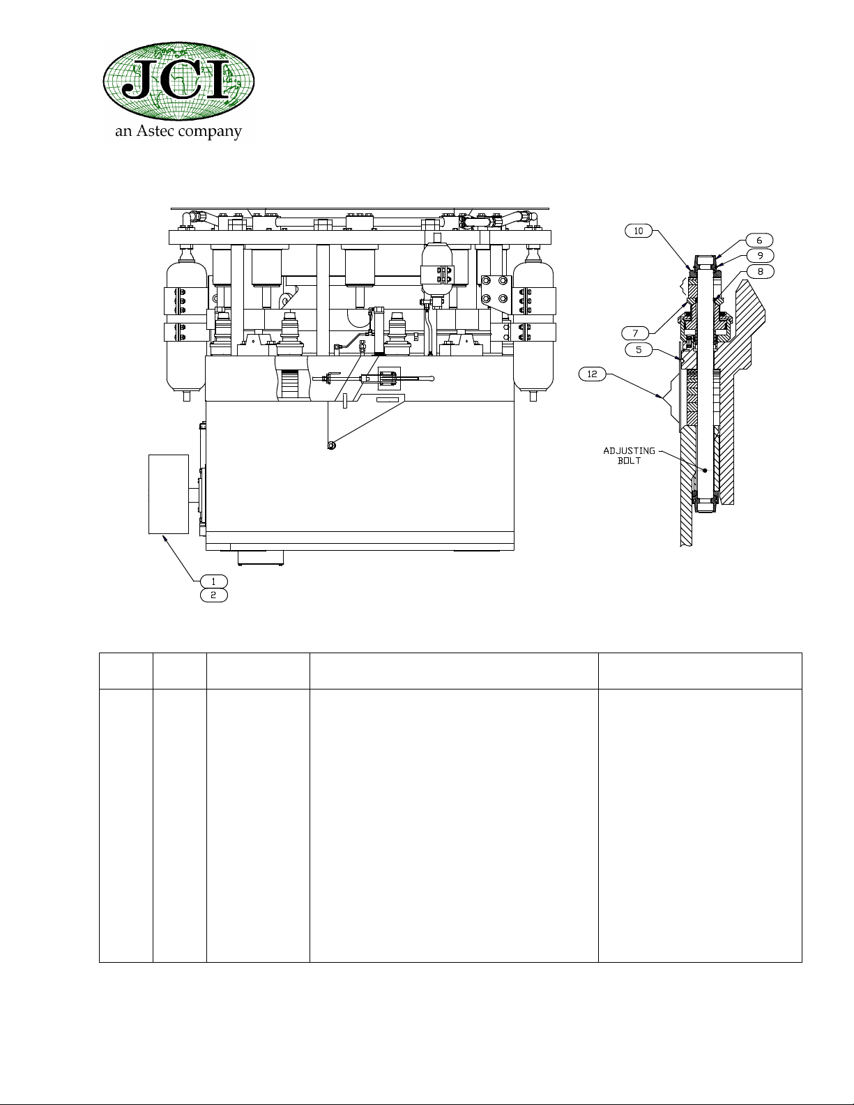
• Before starting the crusher visually check the tramp iron and clamp cylinder pressure gauges on the
hydraulic manifold. Both pressures should range from 2700 psi to 3000 psi. Occasionally check the
system pressure gauge with the hydraulic pump motor running. This pressure shall not exceed 3000
psi.
• Avoid stopping the crusher with material inside the crushing chamber. In the event that the crushing
chamber is full of rock use the hydraulic clearing feature. Always inspect the crushing chamber and
U-seat after a clear for loose or jammed rock.
• Do not adjust the close side setting smaller than the recommended minimum setting for your mantle
and bowl liner combination.
• An oil flow meter has been provided as a safety device to protect the crusher components in the
event of a lubrication system failure. Should the flow meter detect a flow of oil less than its preset
value, the electrical panel will activate the warning horn alerting crusher operators that the machine
needs to be shut down immediately to prevent permanent damage to crusher components. In addi-
tion, it is strongly suggested that the control circuit be wired such that, when the warning system is
activated, the feed device feeding the crusher is shut down. The crusher should be shut down imme-
diately after the rock has cleared the crushing chamber (less than 10 seconds).Wear your hard hat at
all times.
• Stop the crusher, lock out power, and tag controls:
1.Before performing any lubrication, maintenance, adjustments, or repairs.
2.Before removing any spilled materials.
3.Before clearing jams or working on the crusher.
4.Whenever any unusual noises or sudden changes in operation are noticed .
• Refer to the JCI Operation Manual for screen safety information. If your copy of the manual is miss-
ing, please contact your local JCI dealer or the JCI Parts Department for a replacement copy.Read
your Operation Manual for your screen. Be sure that you fully understand all phases of screen opera-
tion. A careful and well-trained operator is the best insurance against an accident.

JCI 24/7 Parts Number 888-474-0115
© 2006 JCI
Factory Installed Counter Weight Configuration
ITEM QTY PART
NUMBER DESCRIPTION COMMENTS
1 1 450034 LEADING 1200LS
2 1 450035 MEDIUM 1200LS
3 1 450035 MEDIUM 1200LS
4 1 450035 MEDIUM 1200LS
5 1 450035 MEDIUM 1200LS
6 1 450035 MEDIUM 1200LS + 1 1/4 SHIM 450089 - 1/4 SHIM
7 1 450035 MEDIUM 1200LS + 1 1/4 SHIM 450089 - 1/4 SHIM
8 1 450035 MEDIUM 1200LS + 2 1/4 SHIM 450089 - 1/4 SHIM
9 1 450035 MEDIUM 1200LS + 2 1/4 SHIM 450089 - 1/4 SHIM
10 1 450035 MEDIUM 1200LS + 2 1/4 SHIM 450089 - 1/4 SHIM
11 1 450035 MEDIUM 1200LS + 2 1/4 SHIM 450089 - 1/4 SHIM
12 1 450035 MEDIUM 1200LS + 2 1/4 SHIM 450089 - 1/4 SHIM

JCI 24/7 Parts Number 888-474-0115
© 2006 JCI
Factory Installed 1200LS Manganese Configuration
ITEM QTY PART
NUMBER DESCRIPTION COMMENTS
1 1 450128X MANTLE 66lbs poured
2 1 450127X BOWL LINER 44lbs poured
3 110 lbs 090037 MANGANESE BACKING MATERIAL
2
1

JCI 24/7 Parts Number 888-474-0115
© 2006 JCI
Drive Sheave and Miscellaneous Items
ITEM QTY PART
NUMBER DESCRIPTION COMMENTS
1 1 060039 SHEAVE 6GR 8V 24.6 PD 24.8 OD
2 1 060005 QD BUSHING M 2 - 15/16
5 1 450076 SEAL, SHIM GUARD
6 8 450148 ADJ BOLT COUPLER 2 SPLITS
7 8 450358 ALIGNING WASHER-CLAMP CYL
8 8 084001 O-RING 6227-30
9 8 084065 O-RING PARK 2-329 2.375 OD
10 8 450162 ADJUSTING BOLT WASHER
12 8 450184 SHIM STACK KIT
N/A 1 090034 WRENCH ALLEN 7/8
N/A 1 450133 CONE LIFTING EYE
N/A 1 450030 WRENCH CLAMP CYLINDER
N/A 1 450132 WRENCH MANTLE NUT
N/A 1 N/A MOTOR 200HP

JCI 24/7 Parts Number 888-474-0115
© 2006 JCI
Decals
ITEM QTY PART
NUMBER DESCRIPTION COMMENTS
20 1 090023 DECAL, DRIVE GUARDS
21 1 090024 DECAL, EYE PROTECTION
22 1 090025 DECAL, HEARING PROTECTION
23 1 090026 DECAL, LOCKOUT
24 1 090027 DECAL, HARDHAT
25 1 090090 DECAL - JCI 1200 LS
26 1 090064 DECAL -DANGER EXP DECOMPRESS
27 1 090065 DECAL-DANGER-SERIOUS INJURY
28 1 090066 DECAL-NOTICE-BLOCK CONE HD
29 1 090067 DECAL-NOTICE-DO NOT ALLOW MAT
30 1 090068 DECAL-CAUTION-CONSULT YR OPER
31 2 090069 DECAL-NON-FLAMABLE GAS
33 1 090074 DECAL - WORLD CLASS...
34 1 090056 DECAL, MADE IN AMERICA
35 1 090022 SERIAL NUMBER PLATE

JCI 24/7 Parts Number 888-474-0115
© 2006 JCI
Kits and Additional Spare Parts
Accumulator Kits
Seal Kits
ITEM QTY PART
NUMBER DESCRIPTION COMMENTS
1 1 450010 ACCUMULATOR KIT 2-1/2 OR 5 GALLON BAG
2 1 450014 ACCUMULATOR KIT 1 GALLON BAG
3 1 450178 ACCUMULATOR KIT 2-1/2 OR 5 GALLON BAG (W/O NUTS)
4 1 450179 ACCUMULATOR KIT 1 GALLON BAG (W/O NUTS)
5 1 450024 ACCUMULATOR BAG 1 GALLON
6 1 450020 ACCUMULATOR BAG 5 GALLON
7 1 360247 ACCUMULATOR BAG 2-1/2 GALLON
8 450266 NITROGEN PRESSURE GAUGE
9 1 450015 ACCUMULATOR CHARGE KIT
10 1 450364 PORT ASSEMBLY
11 1 084069 O-RING FOR THE PORT ASSEMBLY
ITEM QTY PART
NUMBER DESCRIPTION COMMENTS
1 1 450079 SEAL KIT CLAMP CYLINDER ASSY
2 1 450004 SEAL KIT WITH BRASS
3 1 450013 SEAL KIT ADJUSTING JACK
4 1 540053 SEAL KIT RELIEF CYLINDER
Hose Kits
1 1 450495 HOSE KIT
1 1 082010 HOSE 1X144 1M SWIVEL X 1M SW
1 1 082009 HOSE 1/2X160 1/2 M SWIVELX1/2M
1 1 083067 5405-12-16 ADAPTER, PIPE

JCI 24/7 Parts Number 888-474-0115
© 2006 JCI
Table of Contents
Upper Assembly 1200LS/SS ................................................................................. 1
Clamp Cylinder Assembly ...................................................................................... 5
Adjusting Jack Assembly ....................................................................................... 6
Relief Cylinder Assembly 1200LS .......................................................................... 7
Lower Assembly 1200LS ....................................................................................... 8
Wedgeplate Assembly 1200LS .............................................................................. 11
Cone Assembly 1200LS/SS ................................................................................... 12
Pinion Assembly 1200LS ....................................................................................... 13
Floating Plate Assembly ........................................................................................ 14
Pin Clutch Assembly .............................................................................................. 15
Heater Assembly 2000W 120V .............................................................................. 17
Shim Guard ............................................................................................................ 19
Shim Stack Kit ....................................................................................................... 20
External Lube Panel Assembly 1200LS ................................................................. 21
Horn Assembly ....................................................................................................... 24
Lube Panel J-Box Assembly .................................................................................. 25
Bonnet Components ............................................................................................. 26

JCI 24/7 Parts Number 888-474-0115
© 2003 JCI
PAGE 1
06/19/03Rev. 0
REFERENCE # 450519
Upper Assembly 1200LS/SS

REFERENCE # 450519
06/19/03Rev. 0
Upper Assembly 1200LS/SS
JCI 24/7 Parts Number 888-474-0115
© 2003 JCI
PAGE 2

REFERENCE # 450519
06/19/03Rev. 0
Upper Assembly 1200LS/SS
JCI 24/7 Parts Number 888-474-0115
© 2003 JCI
PAGE 3
ITEM QTY PART
NUMBER DESCRIPTION COMMENTS
1 1 4 5 0 0 4 2 B O N N E T
2 1 4 5 0 2 2 1 B O N N E T S U P P O R T
3 8 450055 PRESSURE ROD
4 4 087001 VALVE, RELIEF, 3/8
5 4 450130 WEDGE, BOWL, CASTING
6 4 0 7 6 0 11 N U T, J A M , A D J U S T I N G J A C K
7 8 450006 FLUID CONNECTOR
8 32 080007 O-RING, 2-012
9 1 450065 MANIFOLD BLOCK
10 1 540166 ACCUMULATOR, 1 GAL 1-1/4NPT
11 8 450109 CLAMP CYLINDER ASSEMBLY
12 4 450116 ADJUSTING JACK ASSEMBLY
13 1 082012 HOSE 1/4X 12IN - 04MB X 04MC
14 2 083019 MALE BRANCH TEE, 1/4
15 2 083018 C2404-04-04, MALE CONN TU 1/4
16 4 083017 C2501-04-04, MALE ELBOW T 1/4
17 8 450044 DUST COVER, RELIEF CYLINDER
18 4 083038 PVV-14-F, COUPLER QUICK DISC F
19 4 083051 TMP-14, 1/4 DUST PLUG
20 168 081001 TUBING, 1/4 X .049 WALL
21 4 450218 ROTATION STOP PIN - 1200
22 4 450217 LOWER ROTATION STOP - BOLT ON
23 8 450216 PRESS RING BOLT SOLID MANIFOLD
24 2 540168 ACCUM, 5 GAL 1-7/8-12UN, SPLI
25 1 450511 RING BEAM RELIEF CYL-1200
26 8 450215 RELIEF CLY ASSEMBLY - 1200
27 2 540157 ACCUM BRACKET-5 GAL 180 DEG
28 12 540173 ACCUMULATOR BRACKET BLOCK
29 2 450222 ACCUM MOUNT M/BRACKET-1200
30 8 070180 "CAPSCREW HEX 1"" 8NC X 5 G8 ZIN"
31 8 078030 WASHER, HT, 1
32 2 083022 MALE ELBOW 1/4
33 2 083023 FLARELESS TUBE END CAP 1/4
34 1 083078 PIPE PLUG-1-1/4-PARK 1-1/4HP
35 6 083055 MOUNTING CLIP, 1/4 TUBE
36 8 083124 SPLIT FLANGE, 51H32
37 2 540203 ACCUMULATOR BRACKET, 1 GALLON
38 16 084016 O-RING 6230-12
39 32 070107 CAP SCREW HEX 3/4 10NC X 4-1/2

REFERENCE # 450519
06/19/03Rev. 0
Upper Assembly 1200LS/SS
JCI 24/7 Parts Number 888-474-0115
© 2003 JCI
PAGE 4
40 2 070086 CAP SCREW HEX 5/8 11NC X 5 G5
41 10 070134 CAP SCREW HEX 5/8 11NC X 6 G5
42 4 070014 CAP SCREW HEX 5/8 11NC X2-1/2
43 38 076001 NUT, NYLOCK 5/8-11 NC
44 16 076040 NUT HEAVY HEX JAM 2-1/4X4-1/2
45 6 070055 CAP SCREW HEX 1/4 20NC X 3/4
46 2 070080 CAP SCREW HEX 5/8-11NC X3-1/2
47 9 051006 FB .250 X 1.500
48 32 078026 WASHER, LOCK, 3/4
49 2 090063 OAKUM, DARK
50 8 540236 ANGLE CLIP, 2 X 2 X 3/8
51 20 078000 WASHER, HT, .625
52 4 540303 ACCUM BRKT HD BOLT CLAMP
53 2 450301 ACCUMULATOR BRACKET
54 2 540304 ACCUM BRKT 5 GAL BOTTOM
55 4 070151 SETSCREW 1/2-13NC X 3/4 SOC HD
56 6 078022 WASHER, LOCK, 1/4
57 4 450302 CAP ROT STOP PLG CCF2 1/2-8-12
58 4 084069 O-RING 2-228 32 SPLIT FLANGE
59 8 070415 CAPSCREW HEX 1/2 13NC X 5-1/2
60 8 078025 WASHER, LOCK, 1/2
61 20 070038 CAP SCREW HEX 5/8 11NC X2G5
62 1 450520 HOPPER, 1200LS
63 4 070016 CAP SCREW HEX 1/2 13NC X1-1/2
64 4 076005 NUT NYLOCK 1/2-13NC
65 2 450518 TUBE ASSEMBLY WELDMENT, 1200
66 2 450521 HOSE, ACCUMULATOR, SEE TEXT
68 2 088203 5151HK-24, SAE FLANGE KIT-24
ITEM QTY PART
NUMBER DESCRIPTION COMMENTS

JCI 24/7 Parts Number 888-474-0115
© 2003 JCI
PAGE 5
03/20/03Rev. 0
REFERENCE # 450109
Clamp Cylinder Assembly
ITEM QTY PART
NUMBER DESCRIPTION COMMENTS
1 1 450343 CLAMP CYLINDER
2 1 450359 INSERT CLAMP CYLINDER
3 1 080009 SEAL U-CUP CLAMP CYL 1870-2
4 1 079004 RETAINING RING BRG INC-UR262
5 1 079005 RETAINING RING SMALLEY-BS-437
6 1 080010 SEAL ANCHOR PK CLAMP CY 1870-4
7 1 450000 CLAMP CYLINDER PISTON
8 1 450479 SLEEVE, BRASS, CLAMP CYLINDER
9 1 450480 THREADED COVER CLAMP CYLINDER
10 1 080011 SEAL DUST CLAMP CYL 18939H

JCI 24/7 Parts Number 888-474-0115
© 2003 JCI
PAGE 6
03/20/03Rev. 0
REFERENCE # 450116
Adjusting Jack Assembly
ITEM QTY PART
NUMBER DESCRIPTION COMMENTS
1 1 450114 RAM, ADJUSTING JACK
2 1 450003 CYL WELDMENT, ADJ JACK
3 1 4 5 0 11 0 G U I D E , O U T E R , A D J J A C K C Y L
4 1 450113 GUIDE, INNER ADJ. JACK CYL
5 1 080013 SEAL ADJ JACK POLY, 2500-1
6 1 079006 SNAP RING SH100STPA (5100-100)
7 1 070029 RETAINING RING, WH162

JCI 24/7 Parts Number 888-474-0115
© 2003 JCI
PAGE 7
06/19/03Rev. 0
REFERENCE # 450215
Relief Cylinder Assembly 1200LS
ITEM QTY PART NUMBER DESCRIPTION COMMENTS
1 1 450214 RELIEF CYLINDER - 1200
2 1 540158 PISTON CORE
3 1 079002 SNAP RING, 5100-450
4 1 080046 SEAL, RELIEF CYLINDER
5 1 080041 SEAL, RELIEF CYLINDER RCII
6 2 080042 SEAL, SPLIT, RELIEF CYL, RCII

JCI 24/7 Parts Number 888-474-0115
© 2006 JCI
PAGE 8
12/8/06Rev. M
REFERENCE # 450242
Lower Assembly 1200LS

REFERENCE # 450242
12/8/06Rev. M
Lower Assembly 1200LS
JCI 24/7 Parts Number 888-474-0115
© 2006 JCI
PAGE 9
ITEM QTY PART
NUMBER DESCRIPTION COMMENTS
1 1 450243 ASSY PL WEDGE 1200 LS
2 1 450244 ASSY CONE 1200 LS/SS
3 1 450268 ASSY PINION 1200 LS
4 1 450043 RING SEAL BASEFRAME
5 4 450068 PIN PUSH BASEFRAME
6 4 084009 O-RING 6227-27
7 1 450497 PL FLOATING W/ INSERTS
8 1 406087 SHAFT CONE BRAKE
9 1 546467 PIN CLUTCH ASSEMBLY
11 1 450166 PL THRUST
12 1 406109 PL CONE BRAKE
14 1 406014 RING GUIDE CLUTCH
15 1 450227 CVR BRAKE HOUSING 1200
16 3 540129 ROLLER SHIM GUARD
17 8 450069 BOLT ADJ CONNECT QUICK
18 1 450485 ASSY HEATER 2000W 120V
19 1 450603 BASEFRAME MACH (SEE TEXT)
22 2 406110 SHAFT KEY BRAKE
25 4 070130 CAPSCREW HEX 5/16 24NF X 3/4
26 4 070203 CAPSCREW SOC 5/16-18NC X 1-1/2
27 6 070152 CAPSCREW HEX 1 14NF X 3
28 32 070027 CAPSCREW HEX 1/2 13NC X 1-1/4
29 4 070141 SETSCREW SOC 5/8 11NC X 5/8
30 8 450148 CPLR BOLT ADJ 2 SPLITS
31 8 070010 CAPSCREW HEX 5/8 11NC X 1-3/4
32 8 540226 RETAINER ADJ BOLT
33 8 450126 WASHER BOLT ADJ
34 3 070016 CAPSCREW HEX 1/2 13NC X 1-1/2
35 8 084065 O-RING PARK 2-329 2.375 OD
36 4 540222 BASEFRAME STRUT GUARD
37 1 083024 5502-12-12
39 1 083033 PIPE SCH 40 1-1/4 X 26 NPT
40 1 083032 ELBOW SCH 40 1-1/4 NPT 90
41 1 540243 BRKT FILL PIPE
42 1 540191 DIPSTICK
43 1 450157 KEY DRIVE SHEAVE
44 1 620150 ARROW
45 32 078025 WASHER LOCK 1/2
46 8 078014 WASHER LOCK 5/8
This manual suits for next models
1
Table of contents
Other ASTEC Industrial Equipment manuals
Popular Industrial Equipment manuals by other brands

Automatic
Automatic LPM200 Operator's & installation manual

SCHUNK
SCHUNK AGE-F-XY Series Assembly and operating manual

SignWarehouse
SignWarehouse enduraPRESS MP5 user manual

3M
3M UniPresser 3M710 instructions

TSCHAN
TSCHAN SD-5 Installation and Operation Manua

Siemens
Siemens HiPath 3000 operating instructions

Tundra
Tundra TUNMAGL0100 user manual

Siemens
Siemens Motion 701 BTE user guide

VS
VS DATAGAUSS MAX-LG ZZ201240 operating manual

HARRISTON INDUSTRIES
HARRISTON INDUSTRIES 4240 CLOD HOPPER Operator's manual

HOLZMANN MASCHINEN
HOLZMANN MASCHINEN AKM610ECO user manual

Branick
Branick 5500 Installation, Operation and Repair Parts Information