manuals.online logo
Brands
  1. Home
  2. •
  3. Brands
  4. •
  5. Christie
  6. •
  7. Controllers
  8. •
  9. Christie E510 User manual

Christie E510 User manual

Christie E510 LED Display
Controller
User Guide
020-001941-01
NOTICES
COPYRIGHT AND TRADEMARKS
Copyright © 2021 Christie Digital Systems USA, Inc. All rights reserved.
All brand names and product names are trademarks, registered trademarks or trade names of their respective holders.
GENERAL
Every effort has been made to ensure accuracy, however in some cases changes in the products or availability could occur which may not be reflected in this document.
Christie reserves the right to make changes to specifications at any time without notice. Performance specifications are typical, but may vary depending on conditions
beyond Christie's control such as maintenance of the product in proper working conditions. Performance specifications are based on information available at the time of
printing. Christie makes no warranty of any kind with regard to this material, including, but not limited to, implied warranties of fitness for a particular purpose. Christie
will not be liable for errors contained herein or for incidental or consequential damages in connection with the performance or use of this material. Canadian
manufacturing facility is ISO 9001 and 14001 certified.
For the most current technical documentation and office contact information, visit www.christiedigital.com.
WARRANTY
Products are warranted under Christie’s standard limited warranty, the details of which are available at https://www.christiedigital.com/help-center/warranties/ or by
contacting your Christie dealer or Christie.
PREVENTATIVE MAINTENANCE
Preventative maintenance is an important part of the continued and proper operation of your product. Failure to perform maintenance as required, and in accordance
with the maintenance schedule specified by Christie, will void the warranty.
REGULATORY (if applicable)
The product has been tested and found to comply with the limits for a Class A digital device, pursuant to Part 15 of the FCC Rules. These limits are designed to provide
reasonable protection against harmful interference when the product is operated in a commercial environment. The product generates, uses, and can radiate radio
frequency energy and, if not installed and used in accordance with the instruction manual, may cause harmful interference to radio communications. Operation of the
product in a residential area is likely to cause harmful interference in which case the user will be required to correct the interference at the user’s own expense. Changes
or modifications not expressly approved by the party responsible for compliance could void the user's authority to operate the equipment.
CAN ICES-3 (A) / NMB-3 (A)
이 기기는 업무용(A급)으로 전자파적합등록을 한 기기이오니 판매자 또는 사용자는 이점을 주의하시기 바라며, 가정 외의 지역에서 사용하는 것을 목적으로 합니다.
ENVIRONMENTAL
The product is designed and manufactured with high-quality materials and components that can be recycled and reused. This symbol means that electrical and
electronic equipment, at their end-of-life, should be disposed of separately from regular waste. Please dispose of the product appropriately and according to local
regulations. In the European Union, there are separate collection systems for used electrical and electronic products. Please help us to conserve the environment we
live in!
Christie E510 LED Display Controller User Guide 3
020-001941-01 Rev. 1 (07-2021)
Copyright © 2021 Christie Digital Systems USA, Inc. All rights reserved.
Features ..............................................................................................................................5
Video source features ............................................................................................................5
Specifications .......................................................................................................................6
Applications..........................................................................................................................6
Cascading devices.................................................................................................................8
Christie E510 LED Display Controller interface and ports.............................................................8
Dimensions ........................................................................................................................11
Home screen ......................................................................................................................11
Terminology .......................................................................................................................12
Related documentation ........................................................................................................12
Installing the Christie E510 LED Display Controller software .....................................................14
Logging into the controller software ...................................................................................14
Setting the input resolution ..................................................................................................14
Resolution requirements...................................................................................................15
Identify the screen cabling path............................................................................................15
Adjusting the initial picture coordinates..................................................................................16
Adjusting the image brightness.............................................................................................17
Adjusting the image quality..................................................................................................17
Setting the redundancy backup.............................................................................................17
Testing the communication between thecontroller and tiles.......................................................18
Reviewing the tile configuration.............................................................................................18
Loading a cabinet configuration file........................................................................................19
Adjusting dark and light lines between tiles ............................................................................19
Displaying a picture when there is no signal ...........................................................................19
Changing the display to black when there is no signal..............................................................20
Restoring the factory settings ...............................................................................................20
Locking the controller ..........................................................................................................20
Color matching LED modules ................................................................................................21
Calibrating replacement LED modules ....................................................................................22
Controlling the status of the display.......................................................................................22
Mirroring the image.............................................................................................................22
Content
Christie E510 LED Display Controller User Guide 4
020-001941-01 Rev. 1 (07-2021)
Copyright © 2021 Christie Digital Systems USA, Inc. All rights reserved.
Mapping function.................................................................................................................26
Loading RCFG files ..............................................................................................................27
Setting alarm thresholds......................................................................................................27
Adjusting image settings......................................................................................................28
Saving to RV card ...............................................................................................................28
Setting redundancy .............................................................................................................29
Storing settings in presets....................................................................................................29
Setting up a backup video source..........................................................................................29
Reducing time delay between input of video signal..................................................................30
Restoring factory default settings..........................................................................................31
Determining current screen time...........................................................................................31
Adjusting OLED brightness ...................................................................................................31
Checking the hardware version.............................................................................................31
Setting communication and network parameters.....................................................................32
Setting the Working mode....................................................................................................32
Setting the OLED menu screen language................................................................................33
Adjusting individual Gamma for RGB .....................................................................................34
Configuring the screen from the web page .............................................................................34
Updating the firmware.........................................................................................................36
Customizing the sending card name ......................................................................................36
Christie E510 LED Display Controller MIB traps .......................................................................38
Line adjustments do not appear on the module edges..............................................................40
Text displays beyond the button outline.................................................................................40
An image remains on the display after disconnecting the source ...............................................40
Christie E510 LED Display Controller User Guide 5
020-001941-01 Rev. 1 (07-2021)
Copyright © 2021 Christie Digital Systems USA, Inc. All rights reserved.
Christie Velvet LED Display System tiles are modular, high-quality image display units that can be configured to
achieve an HD display, depending on the pixel pitch of the tile being installed.
Each Christie E510 LED Display Controller can support a maximum number of tiles, which varies depending on the
pixel pitch of the tiles in the array. The configuration to achieve an HD display differs by the pixel pitch of the tile, as
outlined in the table below.
Pixel pitch
Array size
Maximum number of tiles per controller
0.96 mm
3 x 3
9 tiles
1.2 mm
4 x 4
16 tiles
1.6 mm
5 x 5
25 tiles
1.9 mm
6 x 6
36 tiles
2.5 mm
8 x 8
64 tiles
Understand the important features of the Christie E510 LED Display Controller.
• Input of ultra-high color depths: 10-bit/12-bit RGB 4:4:4/YCbCr 4:4:4, with input resolutions up to
1920×1200@60Hz
• Low latency—Less than 1ms (when the start position of image is 0.)
• Auto LED screen configuration
• Web control
• Image mirroring
• Dual working modes—Working as sending card and fiber converter
• Pixel level brightness and chroma calibration
• Supports individual Gamma adjustment for RGB when the color depth of input source is 10-bit or 12-bit.
• Monitoring of inputs
• One-click backup and recovery
• Multiple E510 units can be cascaded.
Under the video source features for the Christie E510 LED Display Controller.
Input connector
Color depth
Sampling format
Maximum input resolution
HDMI 1.4a
8-bit
RGB 4:4:4
YCbCr 4:4:4
YCbCr 4:2:2
YCbCr 4:2:0
1920×1200@60Hz
10-bit/12-bit
1920×1080@60Hz
Single-link DVI
8-bit
1920×1200@60Hz
Product overview
Christie E510 LED Display Controller User Guide 6
020-001941-01 Rev. 1 (07-2021)
Copyright © 2021 Christie Digital Systems USA, Inc. All rights reserved.
Learn the specifications of the Christie E510 LED Display Controller.
Specification
Description
Electrical parameters:
Input voltage
100 V–240 V AC
Rated power consumption
20 W
Operating environment:
Temperature
-20°C to 60°C (-4°F to 140°F)
Humidity
10% RH–90% RH, non-condensing
Storage temperature
-20°C to 70°C (-4°F to 158°F)
Packing information:
Carrying case
550 mm × 440 mm × 175 mm
(21.7 x 17.3 x 6.9 inches)
Packing box
530 mm × 140 mm × 410 mm
(20.9 x 5.5 x 16.1 inches)
Accessories
1 × Ethernet cable
1 × DVI cable
1 × USB cable
1 × HDMI cable
1 × Power cord
Dimensions
482.6 mm × 356.0 mm × 50.1 mm
(10 x 14 x 2 inches)
Space
1U
Net Weight
4.6 kg (10.1 lbs)
Certifications
RoHS, EMC, FCC, IC, LVD
The E510 can work as a sending card or fiber converter, meeting multiple application needs.
• Scenario 1: Application of Sending Card mode
On the OLED menu screen, choose Working Mode > Sending Card. This mode uses the optical ports or
Gigabit Ethernet ports to output video signals.
10-bit/12-bit
1920×1080@60Hz
3G-SDI
Maximum supported input resolution: 1920×1080@60Hz.
3G-SDI input sources do not support input resolution and color depth settings.
The Gamma value can be adjusted for 8-bit input sources and cannot be adjusted for 10-bit or 12-bit
input sources.
Product overview
Christie E510 LED Display Controller User Guide 7
020-001941-01 Rev. 1 (07-2021)
Copyright © 2021 Christie Digital Systems USA, Inc. All rights reserved.
• Scenario 2: Application of Fiber Converter mode
Set the working mode for the two devices respectively, as shown in the image below. Device 2 uses the
optical ports (for input/output) and Gigabit Ethernet ports (for output/input) to realize optical and electric
signal conversion, which allows for long-distance signal transmission.
• Scenario 3: Application of Dual-Output Working mode
Set the working mode for the two devices respectively, as shown in the image below. Device 1 uses the
optical ports and Gigabit Ethernet ports to output video signals at the same time.
Product overview
Christie E510 LED Display Controller User Guide 8
020-001941-01 Rev. 1 (07-2021)
Copyright © 2021 Christie Digital Systems USA, Inc. All rights reserved.
Learn about cascading devices.
• The control computer must control multiple E510 devices.
Cascade devices using USB IN and USB OUT ports of the E510 devices. Up to eight devices can be cascaded.
• Multiple E510 devices must output image simultaneously.
Cascade devices using GENLOCK IN and GENLOCK LOOP connectors of the E510 devices. Up to eight devices
can be cascaded.
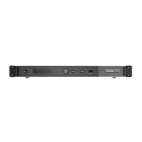
Learn about the interface and physical ports on the Christie E510 LED Display Controller.
The following provides the components at the front of the controller.
1
Operating indicator
• Green—The device is running normally.
1
2
3
4
5
7
6
Product overview
Christie E510 LED Display Controller User Guide 9
020-001941-01 Rev. 1 (07-2021)
Copyright © 2021 Christie Digital Systems USA, Inc. All rights reserved.
• Red—The device is in Standby mode.
2
Standby button
3
OLED operation screen
4
Function knob
5
BACK button—Press to return to the previous menu.
6
INPUT button—Press to choose a video source.
7
USB port—Used to update firmware
The following provides information about the inputs and outputs of the controller.
Inputs/outputs
Description
DVI IN
• Single-link DVI connector
• Custom resolutions supported:
• Maximum width: 3840 pixels
• Maximum height: 2560 pixels
• Supported standard resolutions:
• 1024×768@(24/30/48/50/60/72/75/85/100/120)Hz
• 1280×1024@(24/30/48/50/60/72/75/85)Hz
• 1366×768@(24/30/48/50/60/72/75/85/100)Hz
• 1440×900@(24/30/48/50/60/72/75/85)Hz
• 1600×1200@(24/30/48/50/60)Hz
• 1920×1080@(24/30/48/50/60)Hz
• 1920×1200@(24/30/48/50/60)Hz
• 2560×960@(24/30/48/50)Hz
• 2560×1600@(24/30)Hz
HDMI IN
• HDMI 1.4a compliant
• HDCP 1.4 compliant
• Custom resolutions supported:
• Maximum width: 3840 pixels
• Maximum height: 2560 pixels
• Supported standard resolutions:
• 1024×768@(24/30/48/50/60/72/75/85/100/120)Hz
• 1280×1024@(24/30/48/50/60/72/75/85)Hz
• 1366×768@(24/30/48/50/60/72/75/85/100)Hz
• 1440×900@(24/30/48/50/60/72/75/85)Hz
• 1600×1200@(24/30/48/50/60)Hz
• 1920×1080@(24/30/48/50/60)Hz
Product overview
Christie E510 LED Display Controller User Guide 10
020-001941-01 Rev. 1 (07-2021)
Copyright © 2021 Christie Digital Systems USA, Inc. All rights reserved.
• 1920×1200@(24/30/48/50/60)Hz
• 2560×960@(24/30/48/50)Hz
• 2560×1600@(24/30)Hz
3G-SDI IN
• SMPTE ST 425-1 Level A and B, SMPTE ST 274, ST 296, ST 295 compliant
• Maximum supported input resolution—1920×1080@60Hz
Note: 3G-SDI input sources do not support input resolution and color depth settings.
RJ45 × 6
• 6 Gigabit Ethernet ports
• Maximum loading capacity of a single Ethernet port:
• For 8-bit input sources: 650,000 pixels
• For 10-bit/12-bit input sources: 320,000 pixels
• Support redundancy between Ethernet ports.
OPT1
OPT2
• 10G optical ports
• Single-mode twin-core fiber—Support LC optical connectors; wavelength: 1310 nm;
transmission distance: 10 km; OS1/OS2 recommended.
• Dual-mode twin-core fiber—Support LC optical connectors; wavelength: 850 nm; transmission
distance: 300 m; OM3/OM4 recommended.
• The maximum loading capacity of a single optical port equals that of all the six Ethernet ports.
• 2 OPT inputs/outputs
• The OPT1 works as the primary input or output port, and the 6 Gigabit Ethernet ports
• The OPT2 works as the backup input or output port of OPT1.
• In the sending card mode, both OPT ports and 6 Gigabit Ethernet ports can work as output
ports to output the same image.
• In the fiber converter mode, when the OPT ports work as the input ports, the 6 Gigabit
Ethernet ports work as output ports. When the 6 Gigabit Ethernet ports work as input ports,
the OPT ports work as output ports.
DVI LOOP
DVI loop output
HDMI LOOP
• HDMI loop output
• Support HDCP 1.3 loop output encryption.
3G-SDI LOOP
SDI loop output
HDMI
• Connect to a monitor to monitor the inputs. The output resolution of this connector is
1920×1080@60Hz (fixed output with a width of 1920 pixels and height of 1080 pixels).
• If the input resolution exceeds the monitor resolution, the input is automatically scaled in
proportion and displayed on the monitor starting from its top left.
GENLOCK IN
• GENLOCK input connector
• Genlock type—Blackburst
• Input Genlock sync signal to ensure synchronization and same refresh rate between the output
signals of cascaded E510 units and the external Genlock input signal.
GENLOCK LOOP
Genlock loop output connector. Up to eight E510 units can be cascaded.
ETHERNET
Fast Ethernet port, which connects to PC and supports TCP/IP
USB IN
Input port for cascading devices or connecting to PC
USB OUT
Output port for cascading devices. Up to eight E510 units can be cascaded.
Power supply
100 V–240 VAC
Power switch
ON/OFF
Product overview
Christie E510 LED Display Controller User Guide 11
020-001941-01 Rev. 1 (07-2021)
Copyright © 2021 Christie Digital Systems USA, Inc. All rights reserved.
The following illustrates the dimensions of the product.
The Home screen changes depending on the mode.
• Sending Card mode
In the Sending Card mode, the Home screen of the E510 is shown below.
No.
Description
1
Device name
2
Display the device IP address and sending card name alternatively.
The sending card name can be customized in the Christie E510 LED Display Controller software. See
Customizing the sending card name.
3
The OPT1 port is the master input/output optical port, corresponding to the 6 Gigabit Ethernet ports. The
OPT1 icon has different statuses:
• Always on—The OPT1 port connection works.
Product overview
Christie E510 LED Display Controller User Guide 12
020-001941-01 Rev. 1 (07-2021)
Copyright © 2021 Christie Digital Systems USA, Inc. All rights reserved.
• Off—The OPT1 port is not connected or the connection does not work.
4
1–6: Indicate Ethernet ports 1–6.
• LINK—Ethernet port connection status. The following diamond icon status indicates the Ethernet
connection status.
• Always on—The Ethernet port connection works.
• Off—The Ethernet port is not connected or the connection does not work.
• ACT—Signal transmission status of Ethernet port. The following diamond icon status indicates the signal
transmission status of Ethernet port.
• Flashing—The Ethernet port is transmitting signals.
• Off—The Ethernet port is not transmitting signals.
5
The OPT2 port works as the backup input/output port of OPT1.
• Always on—The OPT2 port connection works.
• Off—The OPT2 port is not connected or the connection does not work.
6
Operating status
/ /
Normal voltage and temperature—Voltage alarm/Temperature alarm/Voltage and
temperature alarms
/ /
Connection status of control ports—USB connected/Ethernet connected/Not connected
When both USB and Ethernet ports are connected to the control computer, USB port has
the priority in control.
/
Buttons on the front panel are locked/unlocked.
Hold down the knob and BACK button simultaneously for three seconds to lock or unlock
the buttons. When the buttons are locked, any button operations are disabled and the
Lock icon appears on the Home screen.
Learn about the components of the LED display system.
Term
Definition
Tile
A cabinet containing several LED modules.
Array
A group of connected tiles forming a larger display.
Controller
Controls the LED display system array and video input source. It is sometimes referred to as the control unit.
Pixel
A group of one red, one green, and one blue dot.
Subpixel
A pixel is comprised of three subpixels, one for each color: red, green, and blue. Each subpixel in LED display
technology is an LED chip.
Pixel pitch
Specifies the distance from the center of one pixel to the center of the next pixel.
Fill factor
Indicates the ratio between the area covered by pixels and the area not covered by pixels.
Additional information on the Christie LED Display System is available in the following documents.
• Christie LED Display Control System Core Series II Installation and Setup Guide (P/N:020-001930-XX)
Product overview
Christie E510 LED Display Controller User Guide 13
020-001941-01 Rev. 1 (07-2021)
Copyright © 2021 Christie Digital Systems USA, Inc. All rights reserved.
• Christie LED Display Control System Core Series II Product Safety Guide (P/N:020-001929-XX)
• Christie E510 LED Display Control System Serial Commands Technical Reference (P/N:020-001940-XX)
• Monitoring the Remote Power 48V (P/N: 020-000850-XX)
Christie E510 LED Display Controller User Guide 14
020-001941-01 Rev. 1 (07-2021)
Copyright © 2021 Christie Digital Systems USA, Inc. All rights reserved.
Perform these tasks when configuring the array.
To configure the array, the computer running the Christie E510 LED Display Controller software must be connected to
the controller with a USB A to B cable.
1. Install the Christie E510 LED Display Controller software (on page 14).
2. Set the input resolution (on page 14).
3. Review the screen connections (on page 15).
4. Adjust the initial picture coordinates (on page 16).
5. Adjust the screen brightness (on page 17).
6. Adjust the image quality (on page 17).
7. Set the redundancy backup (on page 17).
8. Test the communication between the controller and the tiles (on page 18).
9. Review and modify the tile configuration (on page 18).
The Christie E510 LED Display Controller software controls the configuration of the array.
1. Disable the firewall.
2. Insert the Christie E510 LED Display Controller software USB flash drive into the computer.
3. Follow the on-screen instructions and install the Christie E510 LED Display Controller software.
To access the configuration features of the controller software, log into the system.
1. Ensure the computer running the controller software is on the same network at the controller.
2. Connect a USB cable between the controller and the computer running the Christie E510 LED Display
Controller software.
3. Launch the Christie E510 LED Display Controller software and log in as the administrator.
a. Click User > Advanced User Login.
b. Login with the password admin.
Set the resolution for the home page display of interface, which must be consistent with the output resolution of the
video source.
1. Log into the Christie E510 LED Display Controller software.
Configuring the array
Christie E510 LED Display Controller User Guide 15
020-001941-01 Rev. 1 (07-2021)
Copyright © 2021 Christie Digital Systems USA, Inc. All rights reserved.
2. Click Screen Configuration.
3. Select Configure Screen and click Next.
4. Switch to the Sending Card tab.
5. In the Set the Sending Card Display Mode section, select the resolution of the video source from the
Resolution list.
Tile
Native resolution
LED009
640 pixels by 360 pixels
LED012
480 pixels by 270 pixels
LED016
384 pixels by 216 pixels
LED019
320 pixels by 180 pixels
LED025
240 pixels by 135 pixels
6. Click Save.
Understand how to calculate the resolutions for the LED display tile array.
• The maximum vertical and horizontal resolutions may vary. Contact Christie Technical Support if required.
• 8 bit sources (30Hz - 120Hz)—All resolutions from 640 x 480 to 1920 x 1200 refer to standard resolutions
selectable within the Christie E510 LED Display Controller software.
• 8 bit sources (30Hz - 60Hz)—Resolutions 2048 x 1152 and 2560 x 960
• 10/12 bit sources (30Hz - 60Hz)—All resolutions from 640 x 480 to 1440 x 900
• Custom resolutions are accepted by following the formula below. Custom input is restricted to Single Link
DVI/HDMI, using a recommended 94% of the pixels.
The maximum bandwidth of each output is 1Gbit/second, and is calculated with this formula:
Pixel Number x Frame Rate x (Red bit depth + Green bit depth +Blue bit depth)
8bit calculation
1G = Pixel Num x Frame Rate x (8+8+8)
10bit calculation
1G = Pixel Num x Frame Rate x (10+10+10)
12bit calculation
1G = Pixel Num x Frame Rate x (12+12+12)
For example, the 10 bit calculation for a 60Hz DVI signal is:
• 1G = Pixel Number x 60 x (10+10+10)
• Pixel Number: 555,555 x 94% = 522,221 pixels
• Multiply the number of pixels by the number of ports: 522,221 x 4 = 2,088,884
Verify the cabling between tiles is mapped correctlyand adjust as necessary.
Configuring the array
Christie E510 LED Display Controller User Guide 16
020-001941-01 Rev. 1 (07-2021)
Copyright © 2021 Christie Digital Systems USA, Inc. All rights reserved.
1. Connect the computer to the controller with both an HDMI cable and a USB cable.
2. Launch the Christie E510 LED Display Controller software and log in as the administrator.
a. Click User > Advanced User Login.
b. Log in with the password admin.
3. Click Screen Configuration.
4. Select Configure Screen and click Next.
5. Select Standard Screen and specify the number of columns and rows of tiles in the array.
6. Specify the receiving card size.
Tile
Receiving card size
LED009-AP
—
LED012-AP
270 x 240
LED012-AL
240 x 270
LED016-AL
192 x 216
LED019-AL
160 x 180
LED025-AL
120 x 135
7. In the Sending Card Number area, select the controller.
8. Starting with the first tile connected to the controller, left-click and drag the mouse along the rough path the
data cables take between the tiles.
Each tile in the array spans two columns of the grid, one section for each receiver card in the tile. When
dragging the path, ensure that each receiver card in the tile is selected before moving on to the next tile.
9. Click Send to HW.
10. Repeat steps 7 to 9 for each controller in the array.
Adjust the initial coordinates of the pictures on the screen.
1. On the front of the controller, press the menu dial.
When using the menu dial, rotate the dial to move through the items in the menu. To select a menu item or to
set a value, push in the menu dial.
Configuring the array
Christie E510 LED Display Controller User Guide 17
020-001941-01 Rev. 1 (07-2021)
Copyright © 2021 Christie Digital Systems USA, Inc. All rights reserved.
To return to the previous menu, press the button to the bottom right of the menu dial.
2. Select Advanced Settings > Image Offset.
3. Select Start X and push the menu dial.
4. Rotate the dial and set the horizontal offset.
5. Select Start Y and push the menu dial.
6. Rotate the dial and set the vertical offset.
Change the brightness level of each tile to create a uniform brightness across the array.
1. In the Christie E510 LED Display Controller software, click Brightness.
2. To adjust the brightness, use the Brightness Adjustment slider.
3. If the brightness is uneven across the tiles, set all brightness values to zero and raise them to the required
brightness to re-sync the tiles.
4. Click Save To HW.
Change the darker and lighter tones of the source video.
1. In the Christie E510 LED Display Controller software, click Brightness.
2. In the Contrast section of the Brightness Adjustment dialog, use the Gamma slider to adjust the darker and
lighter tones of the source video.
3. Click Save To HW.
If the connection to one tile is lost, the redundancy backup passes information to the other tiles so the display
continues to work normally.
1. In the Christie E510 LED Display Controller software, click Screen Configuration.
2. Select Configure Screen and click Next.
3. Switch to the Sending Card tab.
4. In the Redundancy section, click Add.
Only tiles in the same cascade chain can have a primary-backup redundancy backup relationship.
5. Set the serial number of the primary sending card and port number.
6. Set the serial number of the backup sending card and port number.
A backup tile cannot be set as a primary if it is part of a redundancy backup relationship.
7. Click Add.
Configuring the array
Christie E510 LED Display Controller User Guide 18
020-001941-01 Rev. 1 (07-2021)
Copyright © 2021 Christie Digital Systems USA, Inc. All rights reserved.
8. Add any additional redundancy relationships.
9. Click Close.
10. Click Save.
Verify the array is connected to and recognized by the Christie E510 LED Display Controller.
1. Connect the USB cable between the controller and the computer running the Christie E510 LED Display
Controller software.
2. Launch the Christie E510 LED Display Controller software and log in as the administrator.
a. Click User > Advanced User Login.
b. Login with the password admin.
3. To confirm the display is connected to and recognized by the controller, in the Local System Info area, ensure
Control System has a value of 1.
If the controller is not recognizing the tiles, select System > Reconnect.
4. If the Monitor Information area reports there is no screen, verify the output mode is set to Ports and in the
Christie E510 LED Display Controller software, select System > Reconnect.
5. Switch to the Screen Control tab.
6. To confirm the controller is communicating with all tiles, select a color from the Self Test list and click Send.
If the controller is communicating with all the tiles, each display changes to the selected color.
7. Reset the Self Test to Normal and click Send.
8. Close the Screen Control dialog.
Review the tile configuration reported in the Christie E510 LED Display Controller software.
1. In the Christie E510 LED Display Controller software, click Screen Configuration.
2. Select Configure Screen and click Next.
3. Switch to the Screen Connection tab.
4. Click Read from HW.
5. Review the configuration of the tiles in the array and modify as needed.
The cable layout for the tiles in the array is identified with:
• S—Indicates where the first cable starts.
• Green line—Shows the path of the daisy chain of cables.
• E—Identifies the end of the daisy chain.
Configuring the array
Christie E510 LED Display Controller User Guide 19
020-001941-01 Rev. 1 (07-2021)
Copyright © 2021 Christie Digital Systems USA, Inc. All rights reserved.
After the screen is powered on, if the tile fails to display normally, you must load the cabinet files. The cabinet files are
sent to the controller through the Christie E510 LED Display Controller software.
1. In the Christie E510 LED Display Controller software, click Screen Configuration.
2. Select Configure Screen and click Next.
3. Switch to the Receiving Card tab.
4. Click Load from File.
5. In the Open dialog, navigate to the .rcfg file and click Open.
6. Click Send to Receiving Card.
7. Click Save.
To blend two tiles together, change the brightness of the lines between two tiles.
1. Connect the computer to the controller with both an HDMI cable and a USB cable.
2. Launch the Christie E510 LED Display Controller software and log in as the administrator.
a. Click User > Advanced User Login.
b. Log in with the password admin.
3. In the controller software, select Tools > Quickly Adjust Dark or Bright Lines > Adjust Dark or Bright
Lines.
4. At the bottom of the dialog, select the color to display on the array.
5. Select the line to adjust.
• To select more than one line, select each line.
• To adjust only specific pixels, double-click the selected line and choose the pixels to adjust.
Each tile in the array spans two columns of the grid. To select the right edge of the top left tile,select
the bar at the right of the row 1, column 2 sector.
6. Move the Adjust slider until the selected line matches the surrounding LEDs and disappears.
Adjustments are made in real-time but depending on the size of the area being adjusted it may take a few
seconds for the tiles to refresh.
7. After the line adjustment is complete, click Save to HW.
8. In the confirmation dialog, click OK.
9. Repeat steps 4 to 7 for each line to be adjusted.
Configure the controller to display a picture when there is no source signal to the controller.
Configuring the array
Christie E510 LED Display Controller User Guide 20
020-001941-01 Rev. 1 (07-2021)
Copyright © 2021 Christie Digital Systems USA, Inc. All rights reserved.
1. Ensure the main display is showing on the array.
2. In the Christie Controller software select Settings > Prestore Screen.
3. In the Prestore Picture Settings area, click Browse and navigate to the picture to display when there is no
signal to the controller.
4. In the Prestore Picture Settings area, select Save to HW.
5. A confirmation message is displayed when the save is completed.
6. For Disconnect Cable select Prestore Picture.
7. For No DVI Signal select Prestore Picture.
8. In the Function Settings area, select Save to HW.
Configure the controller to display black when there is no source signal to the controller.
1. Ensure the main display is showing on the array.
2. In the Christie Controller Software select Settings > Prestore Screen.
3. For Disconnect Cable select Black.
4. For No DVI Signal select Black.
5. In the Function Settings area, select Save to HW.
Return the configuration back to the factory default settings.
1. In the Christie E510 LED Display Controller software, click Screen Configuration.
2. Select Configure Screen and click Next.
3. Switch to the Sending Card tab.
4. Click Restore Factory Settings.
5. At the confirmation dialog, click OK.
The system is returned to its factory settings.
6. At the completion dialog, click OK.
Disable the ability to navigate the menu and modify the settings from the front of the controller.
1. To disable access to the controller menu, press and hold the menu dial and back button until the controller
screen flashes.
2. To re-enable access to the controller menu, press and hold the menu dial and back button for approximately
15 seconds.

Other manuals for E510

1

Other Christie Controllers manuals

Christie Terra TXO 102 SO Operating and safety instructions

Christie

Christie Terra TXO 102 SO Operating and safety instructions

Christie TVC-1211 User manual

Christie

Christie TVC-1211 User manual

Christie Velvet CorePlus E500 User manual

Christie

Christie Velvet CorePlus E500 User manual

Christie Velvet CorePlus E600 User manual

Christie

Christie Velvet CorePlus E600 User manual

Christie Terra User manual

Christie

Christie Terra User manual

Christie ACT User manual

Christie

Christie ACT User manual

Christie TVC-500 User manual

Christie

Christie TVC-500 User manual

Christie E510 Use and care manual

Christie

Christie E510 Use and care manual

Popular Controllers manuals by other brands

Sentera STR-4 series Mounting and operating instructions

Sentera

Sentera STR-4 series Mounting and operating instructions

ACS contsys MIR-491 operating instructions

ACS contsys

ACS contsys MIR-491 operating instructions

Emerson Fisher L2e instruction manual

Emerson

Emerson Fisher L2e instruction manual

Fujitsu UTY-DMMYM installation manual

Fujitsu

Fujitsu UTY-DMMYM installation manual

Evco EV3B33N7VXRX04 instruction sheet

Evco

Evco EV3B33N7VXRX04 instruction sheet

Eurotech Helios Platform Hardware reference manual

Eurotech

Eurotech Helios Platform Hardware reference manual

Airwell RCW22 Installation and owner's manual

Airwell

Airwell RCW22 Installation and owner's manual

IBM MTM 2145-SV1 Hardware installation guide

IBM

IBM MTM 2145-SV1 Hardware installation guide

Emerson Fisher D4 instruction manual

Emerson

Emerson Fisher D4 instruction manual

Emerson EIM E796 M2CP Installation and maintenance manual

Emerson

Emerson EIM E796 M2CP Installation and maintenance manual

FMC Technologies Sening EPE2 installation manual

FMC Technologies

FMC Technologies Sening EPE2 installation manual

Siemens SIMATIC S5 manual

Siemens

Siemens SIMATIC S5 manual

POLA HP35 Handbook

POLA

POLA HP35 Handbook

ETC ArcSystem Pro D4 Series installation guide

ETC

ETC ArcSystem Pro D4 Series installation guide

Danfoss AMV 130 operating guide

Danfoss

Danfoss AMV 130 operating guide

Nordson Encore Installation, troubleshooting, repair

Nordson

Nordson Encore Installation, troubleshooting, repair

4O3A Station Genius v2 user manual

4O3A

4O3A Station Genius v2 user manual

Evco EVJ 200 quick start guide

Evco

Evco EVJ 200 quick start guide

manuals.online logo
manuals.online logoBrands
  • About & Mission
  • Contact us
  • Privacy Policy
  • Terms and Conditions

Copyright 2025 Manuals.Online. All Rights Reserved.