Christie PASSIVE TO ACTIVE CONVERTER User manual

USER MANUAL
ACTIVE TO PASSIVE CONVERTER

Appendixes
Part III
Serial interface
Connection
Setting up HyperTerminal
Setting up other systems
Firmware upgrade
Using Windows
Using non-Windows terminal
Connectors
VGA input
Monitor redraw
Power input
Stereo sync input
Stereo sync output
Serial plug 1
Serial plug 2
DVI-D left and right output
VGA left and right output
Serial RS-232 cable
Technical specification
Functions
Dimensions
Compatibility
Inputs
Outputs
Supplied material
A
.1
.2
.3
B
.1
.2
C
.1
.2
.3
.4
.5
.6
.7
.8
.9
.10
D
.1
.2
.3
.4
.5
.6
Using the AP-converter
Part II
Keyboard functions
LED indicators
Standby button
Toggle button
Right black button
User button
Menu button
Cursor buttons
On Screen Display
Source Setup
Stereo Setup
Preferences
Advanced
Info
Changes Done
Serial commands
Summary
The help command
Topics
Commands
Linking of units
Technical information
Different types of picture signal
Different types of stereo syncs
Different types of stereo sync
connectors
Left/right sequence in frame
sequential stereo
Handling of sources
A
.1
.2
.3
.4
.5
.6
.7
B
.1
.2
.3
.4
.5
.6
C
.1
.2
.3
.4
.5
D
.1
.2
.3
-----
.4
.5
Setting up the AP-converter
Part I
Requirements
PC and graphics card
Projectors
Screen
Polarizing filters
Viewing glasses
Setup procedure
Connecting projectors
Connecting the PC
Aligning the projector
Setting up linear polarizing filters
Enabling the stereo software
Connect the stereo sync cable
Eyestrain
Checking left and right image
Software parameters
Wrong setup of polarizing filters
Color- or brightness-differences
in projectors
Moving objects
Remote controlling
A
.1
.2
.3
.4
.5
B
.1
.2
.3
.4
.5
.6
C
.1
.2
.3
.4
-----
.5
D
more information on previous page
highly important information
more information on next page
note
more information on both previous and next page
more information available elsewhere

Requirements
Setup procedure
Eyestrain
Remote controlling
A
B
C
D
PC and graphics card
Projectors
Screen
Polarizing filters
Viewing glasses
.1
.2
.3
.4
.5
You need; a frame-sequential
stereo source, a stereo-capa-
ble graphic card and two pro-
jectors.
The AP-converter supports res-
olutions up to 1280x1024.
For the latest information and
related url links please visit
our technical support pages
at www.christiedigital.com
RequirementsA
Setting up the AP-converter
copyright Christie 2002.06
- 3 -
PC and graphics card
To run stereo using the AP-converter you need a frame-sequential stereo source, like a com-
puter with a stereo-capable graphic card.
If you have a stereo-capable graphics card, you need to enable the stereo (some refer to it
as quad buffer). For a PC, this is usually done in the Display Properties.
Any kind of stereo signal running as active stereo (shutter glasses) will be accepted by
the AP-converter.
See www.stereographics.com for a list of stereo-capable graphics cards
Projectors
You need two projectors to display stereo.
To get the most out of your AP-converter, the projectors should support the maximum
resolution of your AP-converter.
Also see chapter C.4 (Eyestrain/Color or brightness differences in projectors).

Requirements
Setup procedure
Eyestrain
Remote controlling
A
B
C
D
PC and graphics card
Projectors
Screen
Polarizing filters
Viewing glasses
.1
.2
.3
.4
.5
You need; a screen with
non-depolarizing surface, two
polarizing filters and a filter
stand.
The filter stand and two filters
are bundled with the AP-con-
verter.
For the latest information and
related url links please visit
our technical support pages
at www.christiedigital.com
RequirementsA
Setting up the AP-converter
copyright Christie 2002.06
- 4 -
Screen
You need a screen with a non-depolarizing surface. Silverscreens and many rear-projection
screens have this quality.
Ordinary white screens or white walls do not have a non-depolarizing surface and may
not be used.
For more information on recommended screens go to http://www.stewartfilm.com
Polarizing filters
You need to place a polarizing filter in front of the lens of both projectors. This is done by
using the provided filters and filter stand.
There are two kinds of polarizing filters, the linear (most common) and circular. The provided
filters are of the linear type.
The filters need to be placed at the correct rotational angle, as described in chapter B.4
(Setup procedure/Setting up linear polarizing filters).
CAUTION! The filters can easily become distorted or gain hot spots if overheated. Max
temperature for filters is 75 degrees Celcius. Precautions should be taken to ensure
proper ventilation. Filters should be considered as a replacable item.

Requirements
Setup procedure
Eyestrain
Remote controlling
A
B
C
D
PC and graphics card
Projectors
Screen
Polarizing filters
Viewing glasses
.1
.2
.3
.4
.5
You need; a pair of polarizing
viewing glasses that match
the polarization of your polar-
ization filters.
The AP-converter comes with
10 pairs of glasses. These
glasses match the linear polar-
ization of the polarization fil-
ters.
For the latest information and
related url links please visit
our technical support pages
at www.christiedigital.com
RequirementsA
Setting up the AP-converter
copyright Christie 2002.06
- 5 -
Viewing glasses
If you need replacement filters visit our web page www.christiedigital.com
You need to use a pair of polarizing viewing glasses that match the polarization type of your
polarizing filters.
There are 10 pairs of glasses delivered with each AP-converter. These match the included
polarizing filters. You may use other viewing glasses as long as they match the polarization
filters in use.
The polarization of your viewing glasses must match the polarization of your polarization
filters.
If you require more pairs of viewing glasses visit our web page www.christiedigital.com

Requirements
Setup procedure
Eyestrain
Remote controlling
A
B
C
D
Connecting projectors
Connecting the PC
Aligning the projector
Setting up linear polarizing filters
Enabling the stereo software
Connect the stereo sync cable
.1
.2
.3
.4
.5
.6
Follow the setup procedure
carefully. This will save you
time.
Use the DVI cable if possible. You can find more technical
information on the connectors
in Part III (Appendixes), chap-
ter C (Connectors).
Setup procedureB
Setting up the AP-converter
copyright Christie 2002.06
- 6 -
Connecting projectors
Use VGA or DVI cables to connect the two
projectors to the left and right VGA or DVI
output channel of the AP-converter. (See
figure B.1-1 on the right).
We recommend using the DVI output on
the AP-converter wherever possible.
The DVI signal has restrictions regarding
cable length.
Connecting the PC
Use a VGA cable to connect the VGA output
of the PC to the VGA input of the AP-con-
verter. (See figure B.1-2 on the right).
The AP-converter is delivered with a standard
cable to be used when there are 15pin VGA
connectors at both ends.
Not all computers have a 15pin VGA
figure B.1-1 (DVI and VGA out)
figure B.1-2 (VGA in)

Requirements
Setup procedure
Eyestrain
Remote controlling
A
B
C
D
Connecting projectors
Connecting the PC
Aligning the projector
Setting up linear polarizing filters
Enabling the stereo software
Connect the stereo sync cable
.1
.2
.3
.4
.5
.6
Correct setup gives optimal
image quality and minimal eye-
strain.
Better alignment gives less
eyestrain and distortions.
Useful downloads are avail-
able from our technical
support pages at
www.christiedigital.com
Setup procedureB
Setting up the AP-converter
copyright Christie 2002.06
- 7 -
Connecting the PC
connector. Some other popular connectors are SUN type 13W3 and SGI type 13W3.
These require an adapter or a special cable to connect to the AP-converter.
Note that SGI and SUN have different pinout for 13W3 connectors.
Aligning the projectors
To get the highest possible stereo image qual-
ity, you need to align the two projectors to
display their picture onto the exact same area. Although it may be difficult to get 100% align-
ment, you will still be able to see stereo even if the projectors are not completely aligned.
Properly aligned projectors enable you to read 2d details without using viewing glasses
or having to black out one of the channels.
To align the projectors you need to get a test image with a cross-hatched geometry pattern.
If you are using MS Windows you may download the freeware `ntest´ monitor testing utility
(© Nokia Monitors) and run the geometry test.
The `ntest´ and test patterns can be found on our technical support pages at
www.christiedigital.com.

Requirements
Setup procedure
Eyestrain
Remote controlling
A
B
C
D
Connecting projectors
Connecting the PC
Aligning the projector
Setting up linear polarizing filters
Enabling the stereo software
Connect the stereo sync cable
.1
.2
.3
.4
.5
.6
The two projectors should be
aligned at the same angle at
all axes.
A projector rack is not
required, but may be useful.
Information on available racks
can be found on our tech-
nical support pages at
www.christiedigital.com
Setup procedureB
Setting up the AP-converter
copyright Christie 2002.06
- 8 -
Aligning the projectors
To set up your projectors, follow the steps below carefully:
Step 1. Placement of projectors
Place the projectors at an appropriate distance from the
screen. Depending on your projectors and screen, this
might be between 3 - 6 meters.
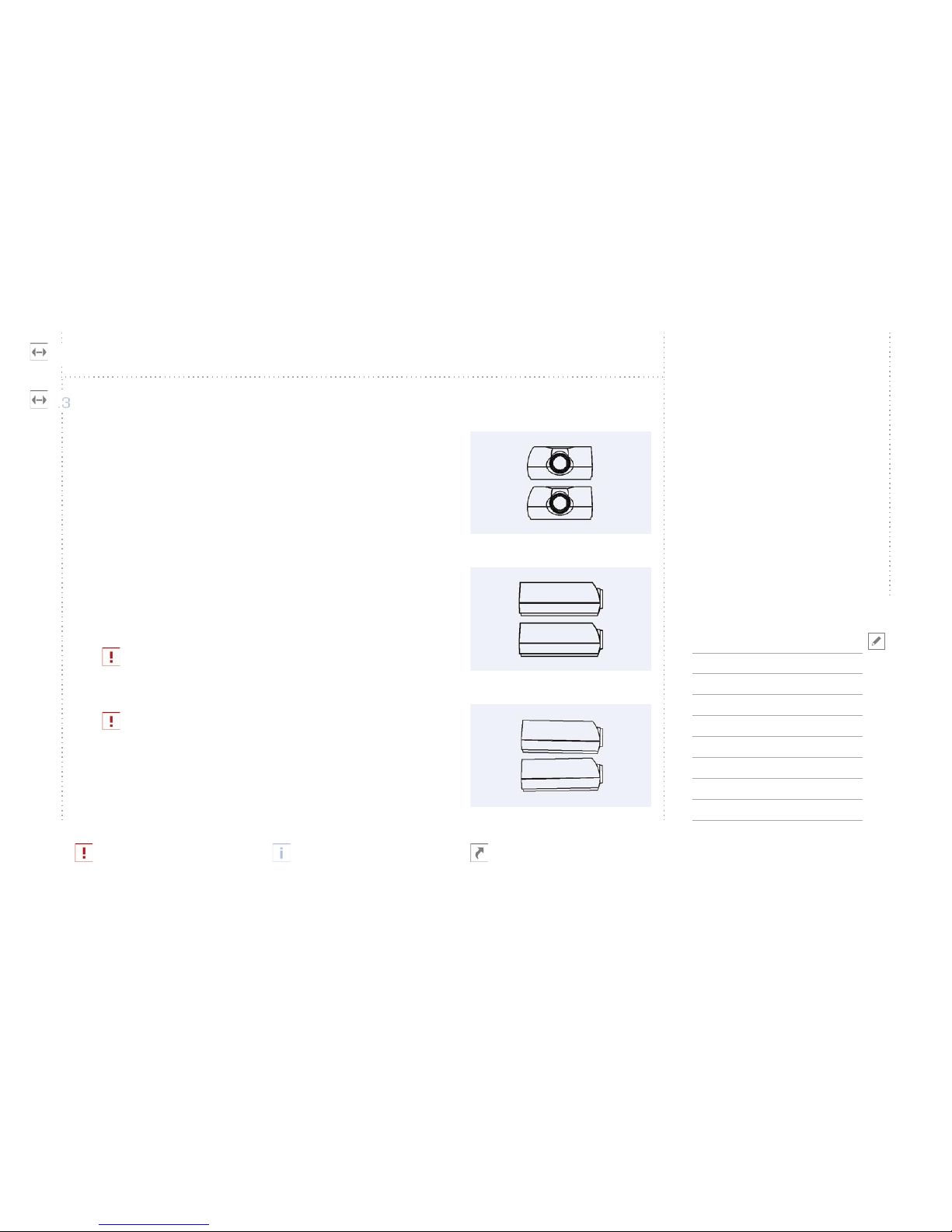
The projectors need to be stacked on top of each other. (See
figure B.3-1 and figure B.3-2 on the right). Try to align the
projectors in such a way that they are perfectly on top of
each other, and that they are at the same angle for all axes.
If your projectors have no lens-shift, you need to position
the lower projector to point slightly up, and the upper
slightly down. (See figure B.3-3 on the right).
Do not use digital keystone correction if you can avoid
it.
Now; power up the projectors. You should be able to see
images on both projectors. If they are not already aligned,
two images will be visible superimposed on each other.
figure B.3-1 (front view)
figure B.3-2 (side view)
figure B.3-3 (no lens-shift)

Requirements
Setup procedure
Eyestrain
Remote controlling
A
B
C
D
Connecting projectors
Connecting the PC
Aligning the projector
Setting up linear polarizing filters
Enabling the stereo software
Connect the stereo sync cable
.1
.2
.3
.4
.5
.6
Follow the alignment steps
carefully.
The outer left and right lines
of the two test patterns need
to overlap.
Refer to your projector user
manual for directions on how
to adjust zoom and focus.
Setup procedureB
Setting up the AP-converter
copyright Christie 2002.06
- 9 -
Aligning the projectors
Step 2. Zoom
Zoom the images to cover as much of your screen as possible.
Also the size of the image needs to be as equal as possible. Normally this is easiest to do by
checking the width of the images. The outer left and right lines of the test image from both
projectors need to overlap.
Also check that the bottom projector’s lower pixel line is at the bottom of the screen. This
can be done with lens shift or physically adjusting the beam direction of the projector, which
normally is done by adjusting the projector legs.
If the image is too small for the screen and you are not able to zoom close enough, you
may have put the projector too close to the screen. If the image is too large, you may
need to put it closer to the screen.
Step 3. Focus
Adjust Focus to get a clear image on both projectors.
If you have problems focusing, the projectors may be too close or too far away from the
screen.

Requirements
Setup procedure
Eyestrain
Remote controlling
A
B
C
D
Connecting projectors
Connecting the PC
Aligning the projector
Setting up linear polarizing filters
Enabling the stereo software
Connect the stereo sync cable
.1
.2
.3
.4
.5
.6
For optimal stereo image qual-
ity fine-tune your setup.
The lens shift function is not
required, but is helpful when
aligning the projector beams.
If you have any problems,
please refer to our technical
support pages at
www.christiedigital.com.
Setup procedureB
Setting up the AP-converter
copyright Christie 2002.06
- 1 0 -
Aligning the projectors
Step 4. Beam alignment
Make the vertical edges overlap by shifting the upper or lower projector physically sideways,
forward or backward.
Step 5. Lens shift
Now adjust the lens shift of the upper projector until the image overlaps the image from the
lower projector perfectly.
If your projectors do not have a lens shift function you must do this by physically adjusting
the beam direction of the projector. This can normally be done by adjusting the projector
legs.
Step 6. Fine-tuning
If you are not satisfied with the result, go back to Step 1. Placement of projectors and fine-
tune the setup.

Requirements
Setup procedure
Eyestrain
Remote controlling
A
B
C
D
Connecting projectors
Connecting the PC
Aligning the projector
Setting up linear polarizing filters
Enabling the stereo software
Connect the stereo sync cable
.1
.2
.3
.4
.5
.6
WARNING: Do not look
directly into the beam of the
projector! That may cause
damage to your eyes!
You must hold your head
(glasses) at a normal viewing
position while checking the
image.
Setup procedureB
Setting up the AP-converter
copyright Christie 2002.06
- 1 1 -
Setting up linear polarizing filters
WARNING: Do not look directly into the
beam of the projector! That may cause
damage to your eyes!
It is important to get the left image at the left
eye. To do this, press the `right black button´
and the projector showing the right eye
will go black. Now put on a pair of polarizing
glasses, and hold one of the polarizing filters
in front of the projector that is not blacked
out. Rotate the filter until the image seen
through the right eye appears as black as
possible. (See figure B.4-1 on the right).
It is important that your head and glasses
are at a normal viewing position horizon-
tally when doing this.
When the correct angle is found, place the
filter into the filter stand at that angle, in
such a way that it covers the projector light
beam. (See figure B.4-2 on the right).
Do the same with the other filter (using the
figure B.4-1 (rotation)
figure B.4-2 (filterstand with filters)

Requirements
Setup procedure
Eyestrain
Remote controlling
A
B
C
D
Connecting projectors
Connecting the PC
Aligning the projector
Setting up linear polarizing filters
Enabling the stereo software
Connect the stereo sync cable
.1
.2
.3
.4
.5
.6
Remember to enable the
stereo in the software, as well
as on the graphic card.
Setup procedureB
Setting up the AP-converter
copyright Christie 2002.06
- 1 2 -
Setting up linear polarizing filters
same projector), but now the images should appear black on the left eye. When the correct
rotational angle is found, place the filter into the filter stand making sure it covers the other
projector light beam.
Press the `right black button´ again to switch on both projectors, and check that the left
eye sees one projector image, and the right eye sees the other image.
Also see chapter C.3 (Eyestrain/Incorrect setup of polarizing filters).
Enabling the stereo software
In addition to enabling the stereo on the
graphic card, you normally in OpenGL applica-
tions also have to enable the stereo in the software you are using. You may also need to
adjust your stereo settings, such as eye distance and focus point.
Correct setting of eye distance and focus point will optimize image quality and minimize
eyestrain.
Please refer to your graphic cards manual for instructions on how to adjust the stereo
settings.

Requirements
Setup procedure
Eyestrain
Remote controlling
A
B
C
D
Connecting projectors
Connecting the PC
Aligning the projector
Setting up linear polarizing filters
Enabling the stereo-software
Connect the stereo sync cable
.1
.2
.3
.4
.5
.6
Setup procedureB
Setting up the AP-converter
copyright Christie 2002.06
- 1 3 -
Connect the stereo sync cable (if possible)
If your graphic card has a stereo sync con-
nector, connect it using a stereo cable that
fits your stereo sync output. If you do not have such a cable, you may need to press the
`toggle button´ on the keyboard to tell the AP-converter which picture is left and right.
If no stereo sync is used, the stereo sync may be lost during presentation and you may
have to press toggle again!
It is strongly recommended to use the stereo sync cable.
See Part II (Using the AP-converter), chapter D (Technical Information), Different
types of stereo sync, for more technical information on this subject.

Requirements
Setup procedure
Eyestrain
Remote controlling
A
B
C
D
Checking left and right image
Software parameters
Wrong setup of polarizing filters
Color- or brightness-differences
in projectors
Moving objects
.1
.2
.3
.4
.5
EyestrainC
Setting up the AP-converter
copyright Christie 2002.06
- 1 4 -
If you feel uncomfortable/dizzy looking at the picture, through the glasses, please check
these settings:
Checking left and right image
To check whether the left and right image is swapped, you may easily turn your glasses
either upside down, or looking outside in (not both!). If the image looks correct this way, the
left and right image are swapped. This may be caused by different things, such as setting
the polarizing filters wrong, bad software settings or wrong definition of stereo sync polar-
ity. You may also use the Left/Right Ident function found in the On Screen Display, under
Special/Testmodes for easier identification.
Software parameters
Bad software parameters such as eye distance, and focus point may cause eyestrain. Unfor-
tunately also bad algorithms for displaying stereo have been discovered in some software.
The best algorithms should have no vertical disparity/displacement at any point of the scene.
You can easily detect this by removing the glasses and pick any random edge/point of an
object. The point should only have a horizontal displacement, and nothing vertically.

Requirements
Setup procedure
Eyestrain
Remote controlling
A
B
C
D
Checking left and right image
Software parameters
Wrong setup of polarizing filters
Color- or brightness-differences
in projectors
Moving objects
.1
.2
.3
.4
.5
EyestrainC
Setting up the AP-converter
copyright Christie 2002.06
- 1 5 -
Wrong setup of linear polarizing filters
A slight wrong rotation of these filters will make the picture greenish or purplish. This makes
the color of the left and right eye slightly different, and may feel uncomfortable.
As the projector lamp gets older, they change their characteristics in color and brightness.
Therefore you should start with projectors of the same age, and when replacing lamps, you
should replace both lamps at the same time.
Color or brightness differences in projectors
As the projector lamp gets older, they change their characteristics in color and brightness.
Therefore you should start with projectors of the same age, and when replacing lamps, you
should replace both lamps at the same time.
Moving objects
If you notice eyestrain when objects are moving, it could be because of the order the left and
right images are output. Not all graphic cards do this properly.
See Part II (Using the AP-converter), chapter D (Technical Information) for more tech-
nical information on this subject.

Requirements
Setup procedure
Eye-strain
Remote controlling
A
B
C
D
The AP-converter may be
remote controlled through the
serial port.
You may set up a chain of
linked AP-converter units, all
controllable from the master
AP-converter.
Remote controllingD
Setting up the AP-converter
copyright Christie 2002.06
- 1 6 -
The serial ports enable you to remote control the AP-converter from a distant location using
a standard RS-232 serial port.
Also the master unit may link to a second AP-converter, the second to a third and so on,
so that you may be able to control all units from a single serial port. To do this, see “Serial
commands”.
For instructions on how to link multiple AP-converters, see Part II (Using the AP-
converter), chapter C.6 (Serial Commands/Linking of units).

Appendixes
Part III
Serial interface
Connection
Setting up HyperTerminal
Setting up other systems
Firmware upgrade
Using Windows
Using non-Windows terminal
Connectors
VGA input
Monitor redraw
Power input
Stereo sync input
Stereo sync output
Serial plug 1
Serial plug 2
DVI-D left and right output
VGA left and right output
Serial RS-232 cable
Technical specification
Functions
Dimensions
Compatibility
Inputs
Outputs
Supplied material
A
.1
.2
.3
B
.1
.2
C
.1
.2
.3
.4
.5
.6
.7
.8
.9
.10
D
.1
.2
.3
.4
.5
.6
Using the AP-converter
Part II
Keyboard functions
LED indicators
Standby button
Toggle button
Right black button
User button
Menu button
Cursor buttons
On Screen Display
Source Setup
Stereo Setup
Preferences
Advanced
Info
Changes Done
Serial commands
Summary
The help command
Topics
Commands
Linking of units
Technical information
Different types of picture signal
Different types of stereo syncs
Different types of stereo sync
connectors
Left/right sequence in frame
sequential stereo
Handling of sources
A
.1
.2
.3
.4
.5
.6
.7
B
.1
.2
.3
.4
.5
.6
C
.1
.2
.3
.4
.5
D
.1
.2
.3
-----
.4
.5
Setting up the AP-converter
Part I
Requirements
PC and graphics card
Projectors
Screen
Polarizing filters
Viewing glasses
Setup procedure
Connecting projectors
Connecting the PC
Aligning the projector
Setting up linear polarizing filters
Enabling the stereo software
Connect the stereo sync cable
Eyestrain
Checking left and right image
Software parameters
Wrong setup of polarizing filters
Color- or brightness-differences
in projectors
Moving objects
Remote controlling
A
.1
.2
.3
.4
.5
B
.1
.2
.3
.4
.5
.6
C
.1
.2
.3
.4
-----
.5
D
more information on previous page
highly important information
more information on next page
note
more information on both previous and next page
more information available elsewhere

Keyboard functions
On Screen Display
Serial commands
Technical information
A
B
C
D
LED indicators
Standby button
Toggle button
Right black button
User button
Menu button
Cursor buttons
.1
.2
.3
.4
.5
.6
.7
Use the `toggle button´
when there is no stereo sync
present, or when using inter-
nal stereo sync.
Use the `toggle button´ to
swap the left and right image.
For the latest functionality
updates please visit our
technical support pages at
www.christiedigital.com
Keyboard functionsA
Using the AP-converter
copyright Christie 2002.06
- 1 8 -
LED indicators
The AP-converter has two led indicators, one
green and one red.
At power on, both the red and green led will
light up. After a few seconds the red led will automatically switch off, leaving the green led
on while the converter is in operation. When the unit is in standby mode, no light will show.
Standby button
The `standby button´ is used to turn the
unit into low-power mode. The button will be
disabled whilst in the OSD.
Toggle button
The `toggle button´ is only used when
there is no stereo sync present, or the AP-
converter runs on internal stereo sync. It
should be used when the left and right image is swapped.

Keyboard functions
On Screen Display
Serial commands
Technical information
A
B
C
D
LED indicators
Standby button
Toggle button
Right black button
User button
Menu button
Cursor buttons
.1
.2
.3
.4
.5
.6
.7
Use the `right black button´
to view 2d without viewing
glasses.
You may download the latest
version of the user manual
from our technical support
pages at
www.christiedigital.com
For the latest functionality
updates please visit our
technical support pages at
www.christiedigital.com
Keyboard functionsA
Using the AP-converter
copyright Christie 2002.06
- 1 9 -
Right black button
The `right black button´ is used for turning
the right channel black.
It may be useful to turn the right channel
black if you need to run 2d without having to use the viewing glasses and the projectors
are not perfectly aligned. It is also useful to check your projector and polarizing filter
setup.
User button
The function of the user button can be defined
in the OSD menu. See chapter B.2 (On
screen display/Global settings).
Menu button
The `menu button´ is used to activate the
`On Screen Display´ (OSD).
Please visit our support pages at www.christiedigital.com for information on the latest
updates on this functionality.

Keyboard functions
On Screen Display
Serial commands
Technical information
A
B
C
D
LED indicators
Standby button
Toggle button
Right black button
User button
Menu button
Cursor buttons
.1
.2
.3
.4
.5
.6
.7
For the latest functionality
updates please visit our
technical support pages at
www.christiedigital.com
Keyboard functionsA
Using the AP-converter
copyright Christie 2002.06
- 2 0 -
Cursor buttons
When in OSD, the `cursor buttons´ are used for navigation within the menus.
Please visit our technical support pages
at www.christiedigital.com for informa-
tion on the latest updates on this func-
tionality.
Other manuals for PASSIVE TO ACTIVE CONVERTER
1
Table of contents
Other Christie Media Converter manuals
Popular Media Converter manuals by other brands

Linksys
Linksys WML11B user guide

Sansonic
Sansonic FT-300A user manual

M-E
M-E Bell-556 TX Operating & assembly instructions

KTI Networks
KTI Networks KC-10TF Series installation guide

METRObility Optical Systems
METRObility Optical Systems twister 2111 Installation & user guide

TRENDnet
TRENDnet TU-S9 user guide