Christie C-RAD 27A User manual

PNEUMATIC TORQUE WRENCH (C-RAD)
USER GUIDE
Ref: WCOI.031 Date: 01.06.15 Issue: 8

CONTENTS
Page Description
1 Introduction
Training Requirements
2 General Safety
3 C-RAD Wrench Models Covered By Manual
Noise & Vibration Levels
4 Accessories Available to Buy or Hire
C-RAD Wrench Features
5 Typical C-RAD Lubro Parts Layout
6 C-RAD Lubro Pre-Check
Assembly
7 Torque Reaction
8 Safe Reaction Zone
9 Setting Torque For Bolt Tightening
Setting Torque For Bolt Loosening
10 Operating The Wrench
11 Optional Rear Safety Trigger Operation
Maintenance And Recalibration
12 Warranty
13 E.C. Declaration of Conformity
-- Calibration Certificate

1
INTRODUCTION
The C-RAD Pneumatic Torque Wrench is a handheld, air driven reversible, non-impacting torque
delivery tool intended to tighten and un-tighten nuts, bolts and threaded fasteners.
The C-RAD Pneumatic Torque Wrench must always be used with the following:-
A Clean Dry Air Supply with a minimum flow of 19L/Sec (40 CFM)
Lubro Control Unit (with filter regulator, lubricator)
Impact Quality Sockets
Ring and pin fastener system (or similar)
Reaction Arm
If the intended use is other than for nuts, bolts and threaded fasteners contact W. Christie (Industrial) Ltd.
It is the responsibility of the user to consider associated site risks before introducing the equipment into
the work-place.
TRAINING REQUIREMENTS
Training on the correct use of the C-RAD Pneumatic torque wrench and C-RAD Lubro Control Unit is
available. Please contact W. Christie (Industrial) Ltd for more information.

2
GENERAL SAFETY
The improper use of pneumatic equipment is unsafe and may result in personal injury. It is important that
operators have read, understood and comply with all instructions in this user guide.
If more than one individual is involved in the operation of the equipment then all must read the user
guide. Good communication must be established to prevent accidents or misunderstandings.
Operators must be equipped with the following personal protective equipment (PPE):-
Eye Protection (Safety Glasses / Goggles)
Safety Footwear (Steel Toe Cap Boots)
Heavy Gloves
Impact quality sockets must be secured to the tool square drive by means of a pin and ring combination.
Care must be taken not to exceed the maximum working pressure of the equipment. See the torque chart
provided. Failure or breakup of components may result in personal injury.
Direct the tool exhaust away from operator / personnel.
Take care not to stand on, run over or trip over pneumatic hoses. Injury may result. To minimise danger
ensure that these lines are not run across walkways, ladders, roadways and doorways, etc and that people
likely to pass through the working area are aware of the danger.
To prevent entanglement with rotating parts operators must not wear loose clothing, ties, jewellery etc…
Long hair must be tied back..
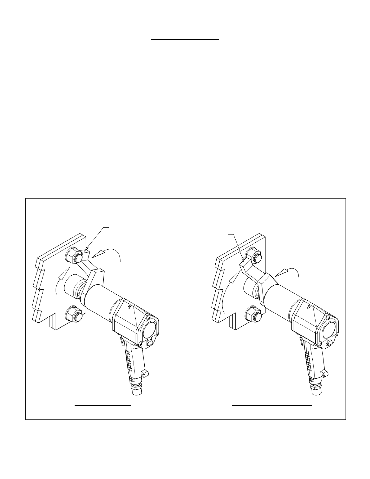
Always keep hands, fingers and body parts clear of the reaction arm at all times. Trapping in this area can
result in serious personal injury.
Before use, check the pneumatic hoses are not cut, split, kinked or damaged in any way. If in doubt Do
not use.
All pneumatic equipment and ancillary products should be inspected for damage and irregularities prior to
use. If in doubt Do not use.
Never lift or drag hoses or cables. This weakens the swagings and puts unnecessary stress on threads and
couplings. Subsequent failure may result in causing injury.
Do not use in the presence of explosive gases or flammable liquids - fire/explosion hazard.

3
C-RAD WRENCH MODELS COVERED BY MANUAL
Standard Models:-
Model
Weight
(Kg)
Speed (RPM)
Torque Range (Nm)
Square
Drive
Single
Auto 2
Minimum
Maximum
C-RAD 1
2.5
290
N/A
20
100
3/4”
C-RAD 5
2.7
55
N/A
80
500
3/4"
C-RAD 5A
4
N/A
250
150
500
3/4"
C-RAD 8
3
35
N/A
160
800
3/4"
C-RAD 8A
4
N/A
160
350
800
3/4"
C-RAD 10L
3.5
30
N/A
150
950
3/4"
C-RAD 10X
4.3
30
N/A
190
1,000
3/4"
C-RAD10XA
5.3
N/A
150
450
1,000
3/4"
C-RAD 14
3.6
20
N/A
275
1,350
3/4"
C-RAD 14A
4.5
N/A
80
400
1,350
3/4"
C-RAD 20
3.9
10
N/A
400
2,000
1”
C-RAD 21
5.4
15
N/A
350
2,100
1”
C-RAD 21A
6.9
N/A
65
800
2,100
1”
C-RAD 27
5.7
10
N/A
550
2,700
1”
C-RAD 27A
7.3
N/A
45
850
2,700
1”
C-RAD 34
6.5
8.5
N/A
700
3,400
1”
C-RAD 40
9.3
11
N/A
800
4,000
1”
C-RAD 40A
10.5
N/A
38
900
4,000
1”
C-RAD 46
10
12
N/A
1,360
4,600
1”
C-RAD 68
13
7
N/A
2,000
6,800
1-1/2”
C-RAD 80
12.5
6.6
N/A
2,700
8,000
1-1/2”
C-RAD 115
25
4.5
N/A
4,100
11,500
1-1/2”
Integrated Nose Cone Models:-
Model
Weight
(Kg)
Speed (RPM)
Torque Range (Nm)
Square
Drive
Single
Auto 2
Minimum
Maximum
C-RAD 10LNA
5.4
N/A
115
400
950
3/4"
C-RAD 21XN
12.4
14
N/A
400
2,100
1”
C-RAD 27XN
12.4
10
N/A
700
2,450
1”
NOISE & VIBRATION LEVELS
NOISE: Equivalent continuous A weighted sound pressure level is less than 85 dB(A).
VIBRATION: Vibration level at handle does not exceed 2.5m/sec.

4
ACCESSORIES AVAILABLE TO BUY OR HIRE
The following accessories are available upon request and can be custom made to suit requirements. Please
contact W. Christie (Industrial) Ltd for more information:-
Special Reactions.
Custom C-RAD Wrench Lifting points.
Nose Cone Extension.
Offset Gearbox.
Custom C-RAD Lubro Units (Typical units listed below):-
-Standard Lubro Units
-Caged / Lockable Lubro Units
-Heavy Duty Water Filter Units
Impact Quality Sockets.
Torque Checking System (Run Down Fixture).
C-RAD WRENCH FEATURES
A - 1/2” BSP
Air Inlet
B - Reaction Arm
C - Spline / Serpentine
D - Output Square
E - Direction Selector Switch (With neutral position)
F - Soft Start Trigger
G - Spirolox Clip
H - Exhaust
Port
Forward
Neutral
Reverse
I - Gearbox
J - Motor

5
TYPICAL C-RAD LUBRO UNIT PARTS LAYOUT
ITEM
NUMBER
DESCRIPTION
1
Filter Regulator
2
Lubricator
3
Inlet Port
4
Outlet Port
5
Regulator Knob
6
Drain Valve
7
Oil Level Window
8
Drip Feed Adjusting / Locking Ring
9
Drip Feed Indicator Sight Glass
10
Oil Filling Plug
C-RAD Lubro Layout may differ than that shown (image for indication only)
(1) Filter Regulator
(2) Lubricator
(3) Inlet Port
(4) Outlet Port
(5) Regulator Knob
(8) Drip Feed
Adjusting / Locking
Ring
(6) Drain Valve
(7) Oil Level Window
(9) Drip Feed
Indicator Sight Glass
(10) Oil Filling
Plug

6
C-RAD LUBRO PRE-CHECK
Check oil level in lubricator and fill to correct level if required. To fill the lubricator with oil:-
- Remove the oil filling plug (10) using a 6mm allen key
- Pour the specified oil into the lubricator, fill to maximum level as indicated on the oil level window
(7) and replace the plug
LUBRICATION: C-RAD Lubro And Air Motor:- ISO 32 Or Equivalent Good Quality Hydraulic Oil.
Do Not Use Synthetic Oils Or Anti-Freeze Solution
ASSEMBLY
Please refer to “Typical C-RAD Lubro Unit Parts Layout” (Previous Page) & Figure below for the
following points:-
Blow out all hoses before connecting. Visually inspect hoses for damage before use. If using non-
Christie supplied hose please ensure hose is correctly rated.
Before connection to Christie C-RAD wrench, ensure the direction selector switch (E) is in the
neutral (middle) position.
Connect the wrench air inlet (A) to the outlet side of the C-RAD lubro control unit, observing air
flow direction arrows.
Connect air supply to inlet side of the C-RAD lubro control unit using a minimum hose size of ½”
bore (12mm). Avoid using ½” bore hoses longer than 5 metres from the supply to the C-RAD lubro
control unit as this will reduce the performance of the wrench. Ensure the connectors are securely
fastened.
Attach the reaction arm (B) to spline (C) adjacent to the output drive (D) of the wrench and secure
with spirolox clip (G).
Make All Connections To The Tool Before Turning On The Air Supply.
The typical connection layout below is based on a W-Christie standard C-RAD Lubro unit.

7
TORQUE REACTION
When the Christie C-RAD wrench is in operation the reaction arm rotates in the opposite direction to the
output square drive and must be allowed to rest squarely against a solid object or surface adjacent to the
bolt to be tightened. (See figure below).
Ensure the Reaction Arm is NOT resting on a sloping or bevelled face.
SPECIAL NOTICE - TIGHT FASTENERS
When tightening or releasing tight fasteners, the torque required to move the nut may be high enough to
keep the reaction locked in one position. This can cause the reaction plate to bend or cause gearbox
failure. To prevent failure, re-position the reaction plate after every two turns of the fastener, i.e operate
the tool briefly in the opposite direction.
Reaction
Reaction
Socket
Socket
Reaction
Clockwise Operation
Counter Clockwise Operation
TRAPPING HAZARD:-
Always keep hands, fingers and body parts clear of the reaction arm when the tool is in use
or trapping injury will result
Reaction

8
SAFE REACTION ZONE
Care must be taken to ensure that the reaction arm is only used within the limitations shown in the figure
below. Failure to observe this instruction will result in premature wear or damage to the wrench. Do not
react on the reaction arm vertical crank. Extreme forces are created which may cause damage to the
wrench. If the application does not allow the use of a standard reaction arm, non-standard reaction arms
are available.
Customers must not modify reaction arms and are strongly advised to contact W. Christie (Industrial) Ltd
for technical assistance.

9
SETTING TORQUE FOR BOLT TIGHTENING
Every Christie C-RAD Wrench is supplied with an individual air pressure calibration graph which relates
torque output to air pressure. Set the torque output as follows:-
1. Ensure direction selector switch (E) is set to “Forward”.
2. Identify the air pressure required using the air pressure calibration graph.
3. Adjust the C-RAD Lubro Control Unit regulator knob (5) (see “Typical C-RAD Lubro Unit Parts
Layout” section) whilst free running the C-RAD wrench until the correct pressure is shown on the
C-RAD Lubro pressure gauge. Do not exceed the maximum air pressure setting of the air pressure
calibration graph.
INFORMATION: While the wrench is free running check that the C-RAD lubro control unit is
supplying approximately six drops of oil per minute. View flow rate through
indicator sight glass (9) (see “Typical C-RAD Lubro Unit Parts Layout” section).
To adjust the C-RAD Lubro oil flow lift the adjusting ring (8) and turn to suit
(clockwise to decrease flow, anti-clockwise to increase flow). Push the locking ring
down to lock the adjustment.
4. When the air pressure is set, return the forward/reverse switch (E) to the neutral position and keep
in this position until the tool is positioned on the fastener.
SETTING TORQUE FOR BOLT LOOSENING
1. Ensure that the Forward/Reverse Switch is set to “Reverse”.
2. Establish maximum air pressure from Air Pressure Graph or tool label and set air pressure for bolt
tightening whilst free running the C-RAD wrench.
3. When the air pressure is set, return the forward/reverse switch (E) to the neutral position and keep
in this position until the tool is positioned on the fastener.
Reverse
Neutral
Forward
‘Z’
Forward
Reverse
Neutral
PART VIEW ON ARROW ‘Z’
(E - Direction Selector Switch)
E - Direction Selector Switch
(With Neutral Position)

10
OPERATING THE WRENCH
1. Fit the wrench with the correct size impact socket to suit the bolt to be tightened and retain with
ring and pin system.
2. Rotate the handle to convenient position relative to the reaction arm.
3. Fit the tool onto the bolt to be tightened / un-tightened with the reaction arm adjacent to the
reaction point (See “Torque Reaction” section).
4. Move the direction selector switch (E) from the neutral position and into either forward or reverse
as required.
5. Squeeze the soft start trigger (F) partially to bring the reaction arm into contact with the reaction
point.
6. Fully press the soft start trigger (F) and keep pressed until the tool stalls (when tightening) or the
fastener is released (when un-tightening). If the trigger is released before the wrench stalls, full
torque will not be applied to the bolt. Once the air motor stalls do not “blip” the trigger, or
incorrect torque will be applied. Release the soft start trigger (F).
7. In use this tool must be supported at all times in order to prevent unexpected release of a fastener
or component failure.
8. If a fastener will not un-tighten when the tool is set to maximum on the calibration certificate, do
not “blip” the trigger repeatedly, use tooling of higher torque output.
9. Remove tool from bolt.
IMPORTANT: If breakdown, malfunction or damage occurs do not attempt to repair, contact
W. Christie (Industrial) Ltd immediately on +44 (0)1709 55 00 88.

11
OPTIONAL REAR SAFETY TRIGGER OPERATION
If the tool is fitted with the Rear Safety Trigger then both the soft start trigger and the rear safety trigger
have to be pressed before the tool can operate. If either of the triggers is released the tool will stop.
To set the required torque, refer to the SETTING TORQUE FOR BOLT TIGHTENING section.
When running the tool both the rear safety trigger and the soft start trigger will need to be pressed to
rotate the drive.
10. Fit the wrench with the correct size impact socket to suit the bolt to be tightened and retain with
ring and pin system.
11. Rotate the handle to convenient position relative to the reaction arm.
12. Fit the tool onto the bolt to be tightened / un-tightened with the reaction arm adjacent to the
reaction point (See “Torque Reaction” section).
13. Move the direction selector switch (E) from the neutral position and into either forward or reverse
as required.
14. Press the rear safety Trigger fully in then Squeeze the soft start trigger (F) partially to bring the
reaction arm into contact with the reaction point.
15. Press the rear safety Trigger fully in then fully press the soft start trigger (F) and keep pressed
until the tool stalls (when tightening) or the fastener is released (when un-tightening). If either
trigger is released before the wrench stalls, full torque will not be applied to the bolt. Once the air
motor stalls do not “blip” the trigger, or incorrect torque will be applied. Release the soft start
trigger then the rear safety Trigger .
16. In use, this tool must be supported at all times in order to prevent unexpected release of a fastener
or component failure.
17. If a fastener will not un-tighten when the tool is set to maximum on the calibration certificate, do
not “blip” the trigger repeatedly, use tooling of higher torque output.
18. Remove tool from bolt.
MAINTENANCE AND RECALIBRATION
To prevent premature failure and ensure confidence in torque supply, it is recommended that this
equipment is serviced and calibrated at least on an annual basis, by W. Christie (Industrial) Ltd.
Check oil level in lubricator and fill if required (See “C-RAD Lubro Pre-Check” Page for details).

12
WARRANTY
Christie C-RAD wrenches come with a one year (1) conditional warranty.
Christie C-RAD Wrenches are guaranteed against manufacturer and material defects, but not against
abuse, misuse or neglect by the user.
The Square Drive is a non warranty item.
When returning tooling for examination, always ensure the reaction arm, impact sockets and C-RAD
Lubro control unit are returned.

13
E.C. DECLARATION OF CONFORMITY
MODELS COVERED: C-RAD1, C-RAD5, C-RAD5A, C-RAD8, C-RAD8A, CRAD10L,
C-RAD10X, C-RAD10XA, C-RAD14, C-RAD14A, C-RAD20
C-RAD21, C-RAD21A, C-RAD27, C-RAD27A, C-RAD34,
C-RAD40, C-RAD40A, C-RAD46, C-RAD68, C-RAD80,
C-RAD115, C-RAD10LNA, C-RAD21XN, C-RAD27XN
DESCRIPTION: Pneumatic Torque Wrench
We hereby declare that the following machinery complies with the essential health and safety
requirements of the European Machinery Directive 2006/42/EC published on the 9th June 2006
W Christie (Industrial) Ltd, Meadowbank Road, Rotherham S61 2NF, United Kingdom.
This machinery has been designed and manufactured in accordance with the following transposed
harmonised European Standard:-
BS EN ISO 12100-2:2003 Safety of Machinery –Technical Principles
BS EN 792-6:2000 Hand-held, non-electric power tools - Safety requirements. Assembly
power tools for threaded fasteners
SIGNED:
NAME: R. G. Askham POSITION: Senior Applications Engineer
On behalf of W Christie (Industrial) Ltd

This manual suits for next models
24
Table of contents