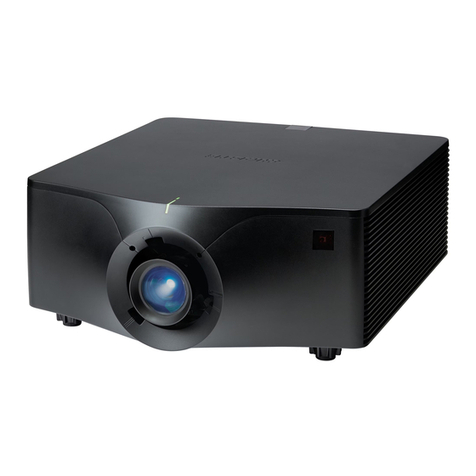
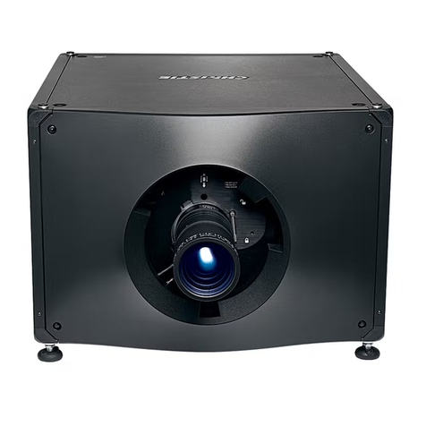
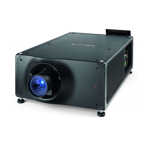
manuals.online logo
Brands
  1. Home
  2. •
  3. Brands
  4. •
  5. Christie
  6. •
  7. Projector
  8. •
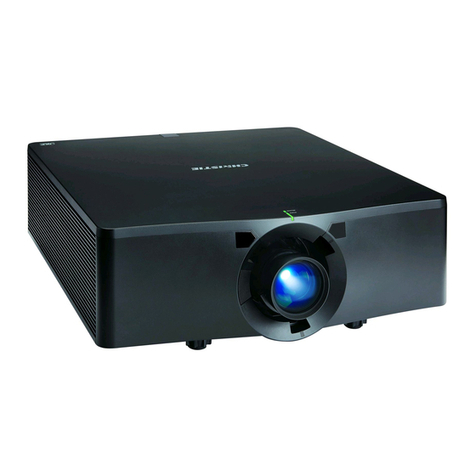
  9. Christie D Series User manual

Christie D Series User manual

D Series
LWU701i/LW751i/LX801i
LWU601i/LW651i
Service Manual
020-000793-01
SPECIFICATIONS AND PARTS ARE SUBJECT TO CHANGE FOR IMPROVEMENT.
Multimedia LCD Projector
October 2015
SERVICE MANUAL
LWU701i
LW751i
LX801i
LWU601i
LW651i
LWU701i/LW751i/LX801i/LWU601i/LW651i
Service Manual 020-000793-01
LIT MAN SERV D2
Warning
The technical information and parts shown in this
manual are not to be used for: the development,
design, production, storage or use of nuclear, chemical,
biological or missile weapons or other weapons of
mass destruction; or military purposes; or purposes that
endanger global safety and peace. Moreover, do not
sell, give, or export these items, or grant permission for
use to parties with such objectives. Forward all inquiries
to the SUPPLIER.
%HVXUHWRUHDGWKLVPDQXDOEHIRUHVHUYLFLQJ7RDVVXUHVDIHW\IURP¿UHHOHFWULFVKRFNLQMXU\KDUPIXO
radiation and materials, various measures are provided in this Multimedia LCD Projector.
Be sure to read cautionary items described in the manual to maintain safety before servicing.
Caution
 :KHQUHSODFHWKHODPSDYRLGEXUQVRQ\RXU¿QJHUV7KHODPSEHFRPHVWRRKRW
 1HYHUWRXFKWKHODPSEXOEZLWKD¿QJHURUDQ\WKLQJHOVH1HYHUGURSLWRUJLYHLWDVKRFN7KH\PD\
cause bursting of the bulb.
3. This projector is provided with a high voltage circuit for the lamp. Do not touch the electric parts of
power unit (circuit) and power unit (ballast), after turning on the projector.
4. Do not touch the exhaust fan, during operation.
5. If replacing to the LCD PRISM assembly, do not hold the FPC of the LCD module assembly.
 8VHWKHFDEOHVZKLFKDUHLQFOXGHGZLWKWKHSURMHFWRURUVSHFL¿HG
Service Warning
1. Features------------------------------------------------------3
 6SHFL¿FDWLRQV -----------------------------------------------4
3. Names of each part---------------------------------------- 5
4. Adjustment---------------------------------------------------6
5. Troubleshooting ------------------------------------------ 14
6. Service points--------------------------------------------- 26
7. Wiring diagram-------------------------------------------- 49
8. Disassembly diagram----------------------------------- 71
9. Replacement parts list---------------------------------102
10.RS-232C communication -----------------------------116
 %ORFNGLDJUDP--------------------------------------------134
12.Connector connection diagram----------------------136
13.Basic circuit diagram-----------------------------------138
Contents
2
LWU701i / LW751i / LX801i / LWU601i / LW651i
LWU701i/LW751i/LX801i/LWU601i/LW651i
Service Manual 020-000793-01
LIT MAN SERV D2
CAUTION FOR SAFETY
3OHDVHUHDGWKLVSDJHEHIRUHWKHUHSDLUZRUN7KLVSDJHH[SODLQVWKHLQGLFDWLRQVRIWKHIROORZLQJ
LWHPVWRNHHSVDIHW\DQGSUHYHQWDQDFFLGHQW
zEntries with graphical symbol explanation
WARNING 7KLVHQWU\ZDUQVRIDULVNRISHUVRQDOVHULRXVLQMXU\RUHYHQGHDWK
CAUTION
7KLVHQWU\ZDUQVRIDULVNRISHUVRQDOLQMXU\SK\VLFDORUSURSHUW\GDPDJH
zTypical graphical symbols explanation
This symbol indicates
warnings and cautions. This symbol indicates
hazard of high voltage. This symbol indicates
mandatory actions.
This symbol indicates
hazard of explosion. This symbol indicates
hazard of hand crush. This symbol indicates
coercing to unplug.
This symbol indicates
hazard of high temperature.
This symbol indicates
prohibited actions.
WARNING
Follow the instructions.
7KHZDUQLQJODEHOVRUPDUNLQJVDUHRQWKHSDUWVZKLFKQHHGVSHFLDODWWHQWLRQ
Follow those notes and the User's Manual - Safety Guide.
Avoid electric shock.
%HFDUHIXODQGXQSOXJWKHSRZHUFRUGDVIDUDVSRVVLEOHGXULQJWKHZRUN%HVXUHWR
unplug when disassembling or assembling.
The projector has high voltage portion and possibly charged portion. If you touch such a
SODFHRURWKHUOLYHSDUWLWFDXVHHOHFWULFVKRFNDQGPD\OHDGWRGHDWK
8VHVSHFL¿HGRUUHFRPPHQGHGFRPSRQHQWV
Use the components which have same characteristic especially about incombustibility
DQGYROWDJHSURRIDVSUHYLRXVIRUNHHSLQJVDIHW\DQGUHOLDELOLW\%HSDUWLFXODUO\VXUHWR
XVHWKHFRPSRQHQWVPDUNHGZLWK in the replacement parts list and circuit diagram.
8VLQJXQVSHFL¿HGRUQRQUHFRPPHQGHGFRPSRQHQWVPD\FDXVHHOHFWULFVKRFNRU¿UH
Keep same style of wiring and components.
This product uses insulating tapes or tubes, and has some components assembled
NHHSLQJGLVWDQFHIURPSDUWLFXODUSRUWLRQWRNHHSVDIHW\DQGUHOLDELOLW\$OVRWKHFDEOHV
DUHZLUHGVRWKDWWKH\NHHSDZD\IURPKLJKWHPSHUDWXUHRUYROWDJHSDUW
%HVXUHWRUHVWRUHWKHPWRSUHYHQWDQHOHFWULFVKRFNDQGD¿UHDIWHU\RXKDYHFKDQJHGWKHP
Do safety inspection after repair work.
&KHFNLIWKHDOOLVUHVWRUHGUHPRYHGSDUWVDQGZLULQJDUHVDPHFRQGLWLRQDVSUHYLRXV
DIWHUUHSDLUZRUN$OVRFKHFNLIDQ\GDPDJHDUHDURXQGWKHUHSDLUHGRUUHSODFHGSDUW
Measure the insulation resistance with megohmmeter after visual inspection. If the
UHVLVWDQFHLVOHVVWKDQ0RKPLWPD\FDXVHHOHFWULFVKRFNDQG¿UH
CAUTION
Take care of LCD panels.
Hold by the frame when disassembling the component including LCD panel. If you hold
it by the FPC cable or the surface of the panel, it may get damaged.
Do not touch the fan motor while it is rotating.
Do not touch the fan motors when you have turned on the projector with the UPPER
CASE removed. It may injure you.
3
LWU701i / LW751i / LX801i / LWU601i / LW651i
LWU701i/LW751i/LX801i/LWU601i/LW651i
Service Manual 020-000793-01
LIT MAN SERV D2
1. Features
!$GYDQFHG1HWZRUN)XQFWLRQV
Not only can you control and monitor the projectors via LAN connection, but also project still or
PRYLQJLPDJHVIURPRQHRUPRUHQHWZRUNHGFRPSXWHUV
!:LUHOHVV1HWZRUN&DSDELOLW\
<RXFDQXVHWKHZLUHOHVVQHWZRUNE\FRQQHFWLQJWKHSURMHFWRUWRD3&XVLQJWKHRSWLRQDO86%
wireless adapter.
!,QVWDQW6WDFN
7ZRSURMHFWRUVRIVDPHPRGHOFDQSURMHFWDQLPDJHRQWKHVDPHVFUHHQXVLQJWKH,QVWDQW6WDFN
IHDWXUH7KH\FDQEHRSHUDWHGVLPXOWDQHRXVO\WRPDNHWKHLPDJHEULJKWHUPRUHRYHUFDQZRUN
alternately by themselves, and once one projector has an accident the other voluntarily starts to
ZRUNWRNHHS\RXUSUHVHQWDWLRQJRLQJ
> LENS MEMORY
The projector is capable of storing the lens shift position.
> Status monitor
The projector displays the present status or the error log with the sub LCD monitor.
> Flexible installation
,WLVSRVVLEOHWRLQVWDOOWKHSURMHFWRUIRUDQ\YHUWLFDOGLUHFWLRQZLWKVSHFL¿HGPRXQWLQJ
accessories.
7KHVLGHSODQHVRIWKHSURMHFWRUVKRXOGEHNHSWYHUWLFDO
> Picture by Picture, Picture in Picture
You can project two images from different input ports on one screen at the same time. With the
remote control, it is easy to turn on/off this function and select the input source for the main and
sub areas.
> eClarity
eClarity is a function to improve the legibility so that it helps to read small letters.
> HDCR
Advanced feature which is the image stabilizer for a clearer image.
> HDBaseT™ covered
Gives one more digital interface to get clearer pictures on a screen.
4
LWU701i / LW751i / LX801i / LWU601i / LW651i
LWU701i/LW751i/LX801i/LWU601i/LW651i
Service Manual 020-000793-01
LIT MAN SERV D2
6SHFL¿FDWLRQV
Liquid crystal
panel
Drive system TFT active matrix
Panel size LX801i: 2.0cm (0.79" type)
LW651i/LW751i: 1.9cm (0.75" type)
LWU601i/LWU701i: 1.9cm (0.76" type)
Number of pixels LX801i: 1024(H) x 768(V)
LW651i/LW751i: 1280(H) x 800(V)
LWU601i/LWU701i: 1920(H) x 1200(V)
Lamp LWU601i/LW651i: 370W UHP
LWU701i/LW751i/LX801i: 430W UHP
Digital
audio/video
signal
HDMI 1Type: T.M.D.S
Signal level: DC 3.3V±5%, AC 0.15-1.56Vp-p
$XGLRVLJQDO/LQHDU3&0IRUPDW6DPSOLQJIUHTXHQF\N+]N+]N+]
2
DisplayPort Data Rate: 2.7Gbps or 1.62Gbps per lane
Lane Count: 4-, 2-, or 1-lane
$XGLR6LJQDO/LQHDU3&0IRUPDW6DPSOLQJIUHTXHQF\N+]N+]N+]
SDI 6'6',6LQJOHOLQN+'6',*6',/HYHO$
Computer
signal
COMPUTER IN (Dsub) 9LGHR$QDORJ9SSȍWHUPLQDWLRQ
H/V. sync.: TTL level (positive/negative)
Composite sync.: TTL level
MONITOR OUT 9LGHR$QDORJ9SSȍRXWSXWLPSHGDQFHSRVLWLYH
H/V. sync.: TTL level (positive/negative)
Composite sync.: TTL level
Video signal VIDEO 9SSȍWHUPLQDWLRQ
HDBaseT* (RJ45) Signal type: PAM16
Differential signal level: 1.9~2.1V
Audio signal AUDIO IN 1P9UPVLQSXWLPSHGDQFHNȍRUPRUHPD[9UPV
2 (L/R)
AUDIO OUT (L/R) P9UPVRXWSXWLPSHGDQFHNȍPD[9UPV
RS-232C Input: Hi: Max. 20V, Min. 2.6V Lo: Typ. –20.0V, Max. 0.8V
Output: Hi: Typ. 8.0V, Min. 5.0V Lo: Typ. –7.0V, Max. –5.0V
USB
TYPE A
(wireless LAN ***)
I/O Level
Amplitude of
differential signal (D+)-(D-)>0.2V and D+>2.0V or (D-)-(D+)>0.2V and D->2.0V
I/O Level
Amplitude of
signal INPUT: “L” 0.8V or less, “H” 2.0V or more
OUTPUT: “L” 0.3V or less, “H” 2.8V~3.6V
USB Mini B **
(Service port)
I/O Level
Amplitude of
differential signal (D+)-(D-)>0.2V and D+>2.0V or (D-)-(D+)>0.2V and D->2.0V
I/O Level
Amplitude of signal
INPUT: “L” 0.8V or less, “H” 2.0V or more
OUTPUT: “L” 0.3V or less, “H” 2.8V~3.6V
Wired LAN HDBaseT* (RJ45) System: 100Base-T
'LIIHUHQWLDOVLJQDOOHYHOa9ȍWHUPLQDWLRQ
LAN* (RJ45) System: 100Base-TX / 10Base-T
'LIIHUHQWLDOVLJQDOOHYHOa9ȍWHUPLQDWLRQ
Wireless LAN
*** IEEE802.11b/g/n See the user's manual of the optional USB wireless adapter.
6SHDNHU 8W×2(mono)
Power supply LWU601i/LW651i
: AC100V-120V/5.2A, AC220V-240V/2.5A
LWU701i/LW751i/LX801i : AC100V-120V/5.9A, AC220V-240V/2.9A
Power consumption LWU601i/LW651i
: AC100V-120V/510W, AC220V-240V/500W
LWU701i/LW751i/LX801i : AC100V-120V/580W, AC220V-240V/560W
Dimensions 498 (W) x 170 (H) x 456 (D) mm (Not including protruding parts)
Weight DSSUR[NJ
Temperature range Standard mode: 32-104°F (0-40°C), Eco mode: 32-113°F (0-45°C),
Storage : -20~60°C
Accessories Remote control x1 User’s manual x 1 Application CD x 1
Security label x 1 Power cord x 1 or 3 Computer cable x 1
Adapter cover x 1 HDMI-DVI cable x 1 Terminal cover x 1
Cable tie x 2 HDMI cable holder x 2
* DC power cannot be provided from these ports.
** The service mini USB port is hidden behind the rear panel (mini USB COVER).
:LUHOHVVQHWZRUNIXQFWLRQUHTXLUHVWKHRSWLRQDO86%ZLUHOHVVDGDSWHU7KHFRPPXQLFDWLRQVSHHGDQGVWDQGDUGLVUHVWULFWHG
GHSHQGLQJRQFLUFXPVWDQFHVOLNHHQFU\SWLRQFRPPXQLFDWLRQPRGHDQGVRRQ
5
LWU701i / LW751i / LX801i / LWU601i / LW651i
LWU701i/LW751i/LX801i/LWU601i/LW651i
Service Manual 020-000793-01
LIT MAN SERV D2
1DPHVRIHDFKSDUW
Projector
(1) Lamp cover
The lamp unit is inside.
(2) Speakers (x2)
(3) Filter cover
7KHDLU¿OWHUDQGLQWDNHYHQW
are inside.
(4) Elevator feet (x2)
(5) Remote sensors (x2)
(6) Lens hole cover
(7) Indicators
(8) Intake vents
(9) Control panel
(10) Status Monitor
(11) AC (AC inlet)
(12) Exhaust vents
(13) Ports
(14) Security bar
(15) Security slot
(16) Safety bar
(17) Battery cover
(8)
(3)
(2)
(4)
(7)
(5)
(4)
(9)
(12)
(8)
(8)
(11) (15) (14)
(1)
(16)
(5)
(6)
(13)
(10)
(2)
(17)
Control panel and Indicators
(1) STANDBY/ON button
(2) INPUT button
(3) MENU button
(4) LENS SHIFT button
(5) ZOOM button
(6) FOCUS - / +buttons
(7) SHUTTER button
(8) FUNCTION button
(9) FILTER indicator
(10) SHUTTER indicator
(11) SECURITY indicator
(12) LAMP indicator
(13) TEMP indicator
(14) POWER indicator
SHUTTER
(5)
(8)
(1)
(3)
(4)
(6)
(2)
(9) (10) (11) (12) (13) (14)
(7)
Ports
(1) COMPUTER IN port
(2) HDBaseT port
(3) LAN port
(4) WIRELESS port
(5) HDMI 1 port
(6) HDMI 2 port
(7) DisplayPort port
(8) VIDEO port
(9) SDI port (LWU701i only)
(10) AUDIO IN1 port
(11) AUDIO IN2 (L, R) ports
(12) AUDIO OUT port
(13) MONITOR OUT port
(14) REMOTE CONTROL IN port
(15) REMOTE CONTROL OUT port
(16) CONTROL port
(1)
(2)
(4)
(3)
(15)
(13)
(8)
(16)
(5) (6)
(7)
(10)
(11)
(12)
(14)
(1)
(2)
(4)
(3)
(15)
(13)
(8)
(16)
(5) (6)
(7) (9)
(10)
(11)
(12)
(14)
LWU601i/LW651i/LW751i/LX801i
LWU701i
$Q\EXWWRQPDUNHGZLWKLVQRWVXSSRUWHGRQWKLVSURMHFWRU
(DFKWLPH\RXSUHVVDQ\EXWWRQH[FHSWIDEXWWRQVWKHID button of current
VHOHFWHG,'QXPEHUOLJKWV
NOTE
Back of
the remote control
Remote control
(1) STANDBY button
(2) ON button
(3) ID - 1 / 2/ 3/ 4buttons
(4) COMPUTER 1 button
(5) COMPUTER 2EXWWRQ
(6) VIDEO button
(7) LAN button
(8) USB TYPE AEXWWRQ
(9) USB TYPE BEXWWRQ
(10) HDMI 1 button
(11) HDMI 2 button
(12) DisplayPort button
(13)
HDBaseT button
(14) SDI button (LWU701i only)
(15) DIGITALEXWWRQ
(16) FOCUS + / - buttons
(17) ZOOM + / - buttons
(18) LENS SHIFT button
(19) LENS MEMORY LOAD / SAVE buttons
(20) LENS LOCK button
(21) OSD MSG button
ŸźŻŹFXUVRUEXWWRQV
(23) ENTER button
(24) AV MUTE button
(25) MENU button
(26) GEOMETRY button
(27) PICTURE button
(28) LAMP button
(29) RESET button
(30) ASPECT button
(31) AUTO button
(32) MAGNIFY ON / OFF buttons
(33) VOL + / -buttons
(34) FREEZE button
(35) PbyP button
(36) MY BUTTON - 1 / 2 / 3/4buttons
(37) Battery cover
(38) Wired remote control port
(1)
(3)
(4)
(7)
(8)
(10)
(13)
(14)
(16)
(20)
(18)
(23)
(24)
(26)
(30)
(34)
(36)
(2)
(5)
(6)
(9)
(11)
(12)
(15)
(17)
(19)
(21)
(22)
(25)
(29)
(33)
(37)
(27) (28)
(38)
(31) (32)
(35)
6
LWU701i / LW751i / LX801i / LWU601i / LW651i
LWU701i/LW751i/LX801i/LWU601i/LW651i
Service Manual 020-000793-01
LIT MAN SERV D2
4-1 Before adjusting
4-1-1 Selection of adjustment
When any parts in the table below are changed, choose the proper adjusting items with the chart.
In addition, setup of the projector according to the chapter 4-8 by service engineers or users is
recommended after all adjustments are done.
Relation between the replaced part and adjustment
Replaced part
Adjustment
AIR
SENSOR
(Chap.4-2)
)OLFNHU
(Chap.4-3) DC OFF
(Chap.4-4) White
balance
(Chap.4-5)
Color
uniformity
(Chap.4-6)
LENS
SHIFT
(Chap.4-7)
DICHROIC OPTICS UNIT
(DICHROIC OPTICS ASS'Y) ×△△△△×
LCD Prism Shift mech. assembly
(LCD/PRISM ASS’Y) ×○○△△○
MAIN PCB
(PWB ASS’Y MAIN) ○○○△△○
LAMP UNIT
(LAMP UNITASS'Y) ×△×△△×
SENSOR-A/B PCB
(PWB ASS’Y SENSOR-A/B) ○×××××
PANEL FAN
(DC FAN G10D13BPWM-P4L301) ○×××××
PBS FAN
(DC FAN CY8028PWM-Z4-L341) ○×××××
BOTTOM CASE
(BOTTOM CASE ASS'Y) ○×××××
○: means need for adjustment. ×: means not need for adjustment. △: means recommended.
$GMXVWPHQW
4-1-2 Setting of condition before adjustments
:DUPLQJXS7XUQRQWKHODPSDQGNHHSLWRQIRU
more than 10 minutes before starting adjustments.
2. Set the image size: Set zoom wide to Max. and
project an image more than 1 m (40 inches) in
diagonal size.
3. Resetting aspect and distortion of the image:
Press the MENU button and select EASY MENU -
RESET. Press the Źor ENTER button to display
RESET dialog and choose the OK with the Ź
button. Set and adjust each item in the EASY
MENU again after adjustment.
4. Displaying the FACTORY MENU: Perform all
adjustments from the FACTORY MENU.
Using the remote control...
a. Press the MENU button and select EASY
MENU - RESET. Press the Źor ENTER button
to display RESET dialog.
b. Next, press the RESET button,then re-press
and hold the RESET button for 3 seconds or
longer (the FACTORY MENU will appear).
Using the control panel of the projector...
a. Press the MENU button and select EASY
MENU - RESET. Press the Źor ENTER button
to display RESET dialog.
b. Next, press the źEXWWRQ¿UVWWKHQSUHVVDQG
hold the źand INPUT button for 3 seconds or
longer (the FACTORY MENU will appear).
Move the cursor among the items of the menu with
Ÿand źbuttons, and select and enter with Źor
ENTER button.
7
LWU701i / LW751i / LX801i / LWU601i / LW651i
LWU701i/LW751i/LX801i/LWU601i/LW651i
Service Manual 020-000793-01
LIT MAN SERV D2
When you replaced the MAIN PCB, SENSOR-A/
B PCB, PANEL FAN, PBS FAN or BOTTOM
CASE, or when you re-attached the PANEL
'8&7WRWKH%27720&$6(PDNHVXUHWR
carry out this adjustment after re-assembling the
SURMHFWRUDQGFOHDQLQJWKHDLU¿OWHU
A-SENS bar
A-SENS >>EXE 1:xxxx 2:xxxx 3:xxxx 4:xxxx END
Adjustment procedure
1. Display the A-SENS bar with the Ÿand ź
buttons in FACTORY MENU - VID-AD1.
2. Press the Źbutton to run automatic adjustment
program. The cell END is highlighted in about 5
PLQXWHVDIWHUWKHDGMXVWPHQW¿QLVKHG
4-2 AIR SENSOR adjustment
Test patterns for the adjustment
NOTE: The test pattern sometimes has
a horizontal line across the screen.
V.COM bar
V.COM Rxxx Gxxx Bxxx Wxxx
Adjustment procedure
1. Display the V.COM bar with the Ÿand źbuttons
in FACTORY MENU - DAC-P.
2. Select the cell R, and use the Ÿand źbuttons
WRDGMXVWVRWKDWWKHÀLFNHUDWWKHFHQWHURIWKH
VFUHHQLVOHVVWKDQWKHÀLFNHUDWWKHSHULSKHU\
:KHQWKHÀLFNHULVDOPRVWVDPHDFURVVWKHZKROH
VFUHHQDGMXVWVRWKDWWKHÀLFNHUDWWKHFHQWHURI
the screen is less than elsewhere.)
3. In the same way, use the cells G and B in turn to
DGMXVWWKHHDFKFRORUÀLFNHU
4-3 Flicker adjustment (V.COM adjustment)
Each color (128/255)
Test patterns for the adjustment
DCOFF menu
DCOFF No.0 R+x G+x B+x
ATTENTION
0DNHWKLVDGMXVWPHQWZRUNDIWHUFRPSOHWLQJWKH
)OLFNHUDGMXVWPHQW.
Adjustment procedure
1. Display the DCOFF menu with the Ÿand ź
buttons in FACTORY MENU - STRIPE.
2. Adjust only the No.0 level.
Select the cell R of No.0 level, and use the Ÿ
and źbuttons to adjust so that vertical bars are
minimized.
3. In the same way, use the cells G and B in turn to
adjust so that vertical bars are minimized.
4-4 DC OFF adjustment (vertical bars adjustment)
64/255
88/255
112/255
136/255
160/255
64
/255 88
/255 112
/255 136
/255 160
/255
ENTER button
8
LWU701i / LW751i / LX801i / LWU601i / LW651i
LWU701i/LW751i/LX801i/LWU601i/LW651i
Service Manual 020-000793-01
LIT MAN SERV D2
Test patterns for the adjustment
SB-CNT bar
SB-CNT R+xx G+xx B+xx W+xx
SB-BRT bar
SB-BRT R+xx G+xx B+xx W+xx
ATTENTION
3HUIRUPWKHIROORZLQJVEHIRUHPDNLQJWKLV
DGMXVWPHQWZRUN
䞉㻌
Set the WHITE BALANCE in SETUP menu
- GEOMETRY CORRECTION - EDGE
BLENDING - WHITE BALANCE - OFFSET
and GAIN to all “+0” .
䞉㻌
Complete the DC OFF adjustment. When only
the LAMP UNIT is replaced, DC OFF adjustment
LVQRWUHTXLUHGVRWKDWWKLVDGMXVWPHQWZRUNFDQ
EHGRQHDIWHU)OLFNHUDGMXVWPHQW
Adjustment procedure
1. Select GAMMAin the FACTORY MENU and press
the RESET button to display the dialog. Select
RESET to reset gamma correction.
2. Display the SB-CNT bar with the Ÿand ź
buttons in FACTORY MENU - GAMMA.
3. Select the cell G, and change the test pattern
to 33-tone grayscale in green with the ENTER
button.
4. Use the Ÿand źbuttons to adjust so that
brightness of 33 steps is best.
5. After completing above, display the SB-BRT bar.
6. Select the cell R or B, and change the test
patterns to 33-tone grayscale with the ENTER
button.
ATTENTION
'RQRWFKDQJHWKHFHOO*RI6%%57WRNHHS
the best contrast ratio.
7. Use the Ÿand źbuttons to adjust so that low-
brightness white balance is best.
8. Select the other cell and adjust in the same way.
9. Display the SB-CNT bar again.
10. Change the test patterns and adjust so that
middle-brightness white balance is best at the
cells R and B in the same way as low-brightness.
11. Repeat adjusting low/middle-brightness white
balance with R and B color so that brightness
and white balance of 33 steps is best.
4-5 White balance adjustment (visual inspection)
Each color
(255/255)
White (255/255)
33-tone grayscale
(W/G)
33-tone grayscale
(W/G)
9
LWU701i / LW751i / LX801i / LWU601i / LW651i
LWU701i/LW751i/LX801i/LWU601i/LW651i
Service Manual 020-000793-01
LIT MAN SERV D2
Test patterns for the adjustment
Adjust tone menu
Tones to be adjusted
Adjustment lattice point nos.
C.UNIF. -MIN- No.1 R±xxx G±xxx B±xxx
-MID-1- No.2
-MID-6- No.17
-MAX-
ON/OFF -ON-
-OFF-
Adjustment lattice point position
ATTENTION
3HUIRUPWKHIROORZLQJVEHIRUHPDNLQJWKLV
DGMXVWPHQWZRUN
䞉
Reset COLOR UNIFORMITY in SETUP menu.
䞉Complete the White balance adjustment.
Preparations
1. Display the Adjust tone menu in FACTORY
MENU - C.UNIF..
Next on the right of "C.UNIF.", 2nd cell from the
left shows tone to be adjusted. Use the Ÿor ź
button to switch the tone.
Next on the right of tones, 3rd cell from the left
shows the no. of adjustment lattice point. Use the
Ÿor źbutton to switch the point.
3 cells from the right show adjusted value of R, G
and B colors. Use the Ÿand źbuttons to adjust
each color.
0DNHFRORUXQLIRUPLW\DGMXVWPHQWVIRUWKH
following 8 tones.
-MIN- tone (approx. 7% input signal)
-MID-1- tone (approx. 14% input signal)
-MID-2- tone (approx. 21% input signal)
-MID-3- tone (approx. 29% input signal)
-MID-4- tone (approx. 39% input signal)
-MID-5- tone (approx. 50% input signal)
-MID-6- tone (approx. 75% input signal)
-MAX- tone (approx. 90% input signal)
3. The adjustment lattice point nos. correspond
to the point positions in the diagram. The color
uniformity of the entire screen can be adjusted by
adjusting the white balance for each of the points
starting in order from the low numbers.
NOTICE: Point No.1 should not be adjusted
because it controls the brightness of the entire
screen. Note that when adjusting a point, it affects
around the point.
4. To temporarily turn correction off, place the
cursor on "C.UNIF." in the Adjust tone menu, and
press the źbutton to display ON/OFF bar. Move
the cursor to ON, and press the źbutton. To turn
it on again, place the cursor on OFF and press
the Ÿbutton.
5. The following two patterns of internal signals are
available for this adjustment. Use the ENTER
button to switch it.
Solid monochrome adjustment color (for G color
adjustment with a color differential meter).
Solid white (for adjustment other than above).
6. Reset values before adjustment, if neccessary.
Single value resets cannot be performed.
When resetting all values, place the cursor on
C.UNIF. in FACTORY MENU, press the RESET
button and select RESET in the dialog.
When resetting the values of single tone, place
the cursor on the tone to be reset, press the
RESET button and select RESET in the dialog.
4-6 Color uniformity adjustment
V/3
V/3
V/6
V/6
H/6 H/6H/3H/3
14
15
16
17
12
13
10 111
6
7
2
8
9
3
4
5
Each color
(each tone)
White (each tone)
(continued on next page)
10
LWU701i / LW751i / LX801i / LWU601i / LW651i
LWU701i/LW751i/LX801i/LWU601i/LW651i
Service Manual 020-000793-01
LIT MAN SERV D2
Adjustment procedure 1
(When a color differential meter is used)
1. First adjust the -MID-1- tone, from G color.
2. Select G of point No.2 and change the
EDFNJURXQGWRVROLG*PRQRFKURPH
3. Measure the illumination at points No. 2, 3, 10
and 11.
The values should be:
No.2 = Y2 [lx], No.10 = Y10 [lx]
No.3 = Y3 [lx], No.11 = Y11 [lx]
4. Points No.2 and No.3 have the average of Y2
and Y3.
Y2 = ( Y2 + Y3 ) / 2 ± 3 [%]
Y3 = ( Y2 + Y3 ) / 2 ± 3 [%]
5. Points No.10 and No.11 have the average of Y10
and Y11.
Y10 = ( Y10 + Y11 ) / 2 ± 3 [%]
Y11 = ( Y10 + Y11 ) / 2 ± 3 [%]
6. Then adjust R and B color of the -MID-1- tone.
&KDQJHWKHEDFNJURXQGWRVROLG:PRQRFKURPH
7. Measure the color coordinates of point No.1 and
PDNHDQRWHRIWKHP
Assume that they are x = x1, y = y1.
NOTE: When the CL-100 or CL-200 color and
FRORUGLIIHUHQFHPHWHULVXVHGWKHǻGHOWDPRGH
is convenient. When point No.1 color coordinate
has been selected, set the slide switch on the
VLGHWRǻZKLOHKROGLQJGRZQWKH)EXWWRQRQWKH
front panel. The measurement shown after this
displays the deviation from point No.1.
8. Measure the color coordinates at point No.2 and
adjust R and B color of point No.2 so that the
coordinates are as follows.
x = x1 ± 0.005 , y = y1 ± 0.005 (as target)
x = x1 ± 0.010 , y = y1 ± 0.015
9. Measure and adjust their color coordinates of
points No.3 to 17 in the same way starting in
order from the small number points.
This completes adjustments required for -MID-1-
tone.
NOTE: Since excessive correction may lead
to a correction data overview during internal
calculations, use the following values for
reference.
No.2 to 5: ± 40 or less
No.6 to 9: ± 50 or less
No.10 to 13: ± 70 or less
No.14 to 17: ± 120 or less
10. Next, adjust the other tones in order of -MIN-,
-MID-3-, -MID-2-, -MID-5-, -MID-4-, -MAX- and
-MID-6-.
11. Adjust each tone as follows, from G color.
-MIN- tone : one and a half of -MID-1- tone
-MID-3- tone : 0 (no adjustment)
-MID-2- tone : a half of -MID-1- tone
-MID-5- tone : 0 (no adjustment)
-MID-4- tone : average of -MID-3- and -MID-5-
tones
-MAX- tone : 0 (no adjustment)
-MID-6- tone : average of -MID-5- and -MAX-
tones
12. Select R or B of point No.2 at -MIN- tone and
FKDQJHWKHEDFNJURXQGWRVROLG:PRQRFKURPH
13. Measure the color coordinates at point No.1 and
PDNHDQRWHRIWKHP$VVXPHWKDWWKH\DUH[ 
x1, y = y1.
14. Now measure the color coordinates at point
No.2 and adjust R and B color of point No.2 so
that the coordinates are as follows.
x = x1 ± 0.010 , y = y1 ± 0.020 (Target)
x = x1 ± 0.040 , y = y1 ± 0.080
15. Similarly, measure and adjust their color
coordinates of points No.3 to 17 starting in order
from the small number points.
1RZPDNHVLPLODUDGMXVWPHQWVIRU5DQG%
color of -MID-3-, -MID-5- and -MAX- tones.
Adjust them in the same way as the -MIN- tone
adjustments in the step 12 to 15 so that the
coordinates are as follows.
x = x1 ± 0.005 , y = y1 ± 0.005
17. Finally, set the values of the -MID-2-, -MID-4-
and -MID-6- tones as follows using the values
already set.
-MID-2- tone : average of -MID-1- and -MID-3-
tones
-MID-4- tone : average of -MID-3- and -MID-5-
tones
-MID-6- tone : average of -MID-5- and -MAX-
tones
(continued on next page)
11
LWU701i / LW751i / LX801i / LWU601i / LW651i
LWU701i/LW751i/LX801i/LWU601i/LW651i
Service Manual 020-000793-01
LIT MAN SERV D2
Adjustment procedure 2
(visual inspection)
1. First adjust G color of the -MIN- tone.
2. Select G of point No.2 and change the
EDFNJURXQGWRVROLG:PRQRFKURPH
3. View point No.2 and 3. Lower the G color
intensity only of the color point whose G color is
more intense than point No.1.
NOTE: When adjusting a point, it affects around
the point as the diagrams.
4. View point No.10 and 11. Lower the G color
intensity only of the color point whose G color
is more intense than point No.1, and raise the
intensity of the point whose color intensity is lower
than point No.1.
5. Now adjust R and B colors of the MIN tone.
6. View points No.2, 3, 10 and 11. Adjust R and B
color of each point so that they have the same
color as point No.1.
Adjustment technique: First, adjust B color of
the point whose color is to be adjusted so that it
approximates that of point No.1. If R color is low at
this time, the image will have cyanish cast, in which
case increase R color. On the other hand, if R color
is excessive, the image will have a reddish cast, in
which case decrease R color. Overall, a cyanish
FDVWPDNHVLWHDV\WRVHHFRORUVKDGLQJ
1H[WYLHZDQGPDNHVLPLODUDGMXVWPHQWVIRU
points No.4, 5, 12 and 13.
8. Then adjust points No.6 to 9 and No.14 to 17.
This completes the -MIN- tone adjustments.
0DNHVLPLODUDGMXVWPHQWVIRURWKHUWRQHVDV
described in steps 1 to 8 above.
No.16 range of effect
No.15 range of effect
No.14 range of effect
No.13 range of effect
No.12 range of effect
No.11 range of effect
No.10 range of effect
No.9 range of effect
No.8 range of effect
No.7 range of effect
No.6 range of effect
No.5 range of effect
No.4 range of effect
No.3 range of effect
14
15
16
17
12
13
10 111
6
7
2
8
9
3
4
5
No.2 range of effect
No.17 range of effect
14
15
16
17
12
13
10 111
6
7
2
8
9
3
4
5
14
15
16
17
12
13
10 111
6
7
2
8
9
3
4
5
14
15
16
17
12
13
10 111
6
7
2
8
9
3
4
5
14
15
16
17
12
13
10 111
6
7
2
8
9
3
4
5
14
15
16
17
12
13
10 111
6
7
2
8
9
3
4
5
14
15
16
17
12
13
10 111
6
7
2
8
9
3
4
5
14
15
16
17
12
13
10 111
6
7
2
8
9
3
4
5
14
15
16
17
12
13
10 111
6
7
2
8
9
3
4
5
14
15
16
17
12
13
10 111
6
7
2
8
9
3
4
5
14
15
16
17
12
13
10 111
6
7
2
8
9
3
4
5
14
15
16
17
12
13
10 111
6
7
2
8
9
3
4
5
14
15
16
17
12
13
10 111
6
7
2
8
9
3
4
5
14
15
16
17
12
13
10 111
6
7
2
8
9
3
4
5
14
15
16
17
12
13
10 111
6
7
2
8
9
3
4
5
14
15
16
17
12
13
10 111
6
7
2
8
9
3
4
5
12
LWU701i / LW751i / LX801i / LWU601i / LW651i
LWU701i/LW751i/LX801i/LWU601i/LW651i
Service Manual 020-000793-01
LIT MAN SERV D2
When you replaced the LCD Prism Shift mech.
assembly or MAIN PCB, make sure to carry
out this adjustment after re-assembling the
projector.
LENS_C bar
(You do not have to care the numbers in this menu.)
Example 1
LENS_C
>>EXE T:xxx B:xxx L:xxx R:xxx NG
Example 2
LENS_C
>>EXE T:168 B:802 L:281 R:803 OK
Example 3
LENS_C
>>EXE T:err B:823 L:306 R:778 NG
Adjustment procedure
1. Display the LENS_C bar with the Ÿand ź
buttons in FACTORY MENU - OPTION. (Example
1)
2. Press the Źbutton to run automatic adjustment
program.
NOTE: During this adjustment, the lens
automatically moves vertically and horizontally.
3. The right-most cell is highlighted after the
DGMXVWPHQW¿QLVKHG&KHFNWKHVWDWXV2.RU1*
displayed in the cell.
OK: The adjustment was successful. (Example 2)
NG: The adjustment was failed. Go to the next
step. (Example 3)
&KHFNWKHIROORZLQJV$IWHUWKHFRQ¿UPDWLRQRU
WKHUHZRUNFDUU\RXWWKHDGMXVWPHQWDJDLQ
+DUQHVVHVDUH¿UPO\FRQQHFWHGWRWKH
connectors EM00, EM01, EM03 and EM04 on
the MAIN PCB.
- None of objects or wires is pinched between the
LENS SHIFT MECH and the lens.
NOTE: Find the cell in which “err” is displayed,
and read the left-most letter (T, B, L or R) in the
cell. It shows the area where the adjustment was
failed.
T: Between the top side frame of LENS SHIFT
MECH and lens body
B: Between the bottom side frame of LENS
SHIFT MECH and lens body
/%HWZHHQWKHDLU¿OWHUVLGHIUDPHRI/(16
SHIFT MECH and lens body
R: Between the lamp-side frame of LENS SHIFT
MECH and lens body
4-7 LENS SHIFT adjustment
13
LWU701i / LW751i / LX801i / LWU601i / LW651i
LWU701i/LW751i/LX801i/LWU601i/LW651i
Service Manual 020-000793-01
LIT MAN SERV D2
zZOOM / FOCUS
1. The ZOOM or FOCUS dialog will appear when you press any of the buttons from ZOOM, ZOOM
-, ZOOM +, FOCUS + and FOCUS -.
2. Use the ZOOM + / - buttons on the remote control or ZOOM button and ŻŹ cursor buttons on
the projector to adjust the screen size.
zLENS SHIFT
Press the LENS SHIFT button. The LENS SHIFT dialog will
DSSHDU8VLQJWKHŸźŻŹEXWWRQVZKLOHWKHGLDORJLVGLV-
played shifts the lens.
zCENTERING
<With the LENS SHIFT dialog>
Press the ENTER or INPUT button.
<In the standby mode>
Press the LENS SHIFT and the FUNCTION buttons for 3
seconds at the same time.

While the lens is moving to the center, the menu disappears
and an hourglass icon appears on the screen. CENTERING
PD\WDNHVRPHWLPHWLOOWKHOHQVUHDFKHVWKHFHQWHU
7KHSURMHFWRUPD\LJQRUHRSHUDWLRQE\EXWWRQVZKLOHPRYLQJWKHOHQV

The CENTERING feature while the projector is in the standby mode is disabled if the STANDBY
MODE item of SETUP menu is set to POWER SAVE. Perform CENTERING before the projector’s
power is turned off, or set the STANDBY MODE to NORMAL.

The adjustable range of LENS SHIFT varies depending on the lens unit mounted on the projector to
maintain picture quality. Therefore, LENS SHIFT adjustment may not reach the end of the indicator
in the dialog. This is not a failure.
4-8 Setup of the projector
zLENS MEMORY SAVE / LOAD / CLEAR
This projector is equipped with memory functions
for the lens adjustments (LENS SHIFT and LENS
TYPE).
To utilize the lens memory feature, press the
POSITION or FUNCTION button while the LENS
SHIFT dialog is displayed.
<SAVE>
To save the current lens adjustments, select a SAVE-(1-3) and press Źor ENTER button.
<LOAD>
7RORDGDVDYHGDGMXVWPHQWVVHOHFWWKH/2$'DQGSUHVVŹRUENTER button.
Using the LENS MEMORY button, the memory can be loaded without the LENS MEMORY dialog.
<CLEAR>
Select CLEAR LENS MEMORY and press the Źor ENTER button. The CLEAR LENS MEMORY
dialog will be displayed. Select the number to be cleared using ŻŹ buttons and press the
EXWWRQ$PHVVDJHGLDORJLVGLVSOD\HGIRUFRQ¿UPDWLRQ3UHVVWKHEXWWRQDJDLQWRFOHDUWKHOHQV
memory.
The following contents are also described in User's manual.
14
LWU701i / LW751i / LX801i / LWU601i / LW651i
LWU701i/LW751i/LX801i/LWU601i/LW651i
Service Manual 020-000793-01
LIT MAN SERV D2
7URXEOHVKRRWLQJ
Ŷ&KHFNSRLQWV
NOTE:
1) The picture above shows the inside of the projector after the UPPER CASE is removed.
7RDFFHVVWKHFRPSRQHQWVRIWKH,13873&%VKRZQLQWKHSLFWXUH\RXQHHGWRGHWDFKWKHEORFN
LQFOXGLQJWKH0$,13&%DQGWRVHSDUDWHWKH,23$1(/DQGWKH,20(7$/IURPWKHEORFN
2) Wiring shown in this picture may differ from mass-products. Refer the chapter of “:LULQJ
GLDJUDP´WRFKHFNWKHSURSHUZLULQJ
3) The component IV01 is located on the reverse side of MAIN PCB.
㻱㼃㻡㻝
㻱㻹㻜㻟
㻱㻹㻜㻞㻱㻤㻜㻝
㻱㻭㻜㻝
㻱㻹㻜㻠
㻱㻤㻜㻠
㻱㻤㻜㻟
㻱㼃㻡㻝
㻼㻡㻜㻝㻘㻌㻼㻢㻜㻝㻘㻌㻼㻣㻜㻝
㻱㻼㻜㻟
㻱㻟㻜㻞
㻱㼃㻟㻞
㻱㼃㻟㻝
㻱㻤㻜㻞
㻱㻸㻡㻜
㻱㻹㻜㻜
㻱㻭㻜㻞
㻱㻹㻜㻝
㻱㼆㻜㻞
㻱㻤㻜㻡
㻱㻤㻝㻟
㻱㻭㻜㻡
㻱㻼㻜㻠
㻱㻤㻜㻜
㻱㼆㻜㻝
㻱㻼㻜㻞
㻱㻤㻜㻤
㻱㻟㻜㻝
㻱㻤㻜㻣
㻱㻤㻝㻠
MAIN PCB
㻱㻤㻜㻢
㻱㻼㻜㻡
INPUT PCB
IC02
IC07
IC03
IC06
15
LWU701i / LW751i / LX801i / LWU601i / LW651i
LWU701i/LW751i/LX801i/LWU601i/LW651i
Service Manual 020-000793-01
LIT MAN SERV D2
*: Be sure to unplug the power cord before measuring resistance.
(5): +14.3V
(7): GND
NO §0Replace MAIN PCB.
or
Replace POWER UNIT CIRCUIT.
2SHQRYHURUGHUN)
§0
Open
NO
Replace TSW (thermal switch).
§0
Open
Replace POWER UNIT CIRCUIT.
(1) +16.8V (Normal STBY)
0V (Saving STBY)
(3) GND for (1)
(9) +5.4V
(19) GND
(20) +16.8V
Go to the next page.
YES
YES
Open
YES
Replace MAIN PCB.
§0
Is
voltage
supplied at pins (5) and
(7) of E800 on the MAIN
PCB?
Power cannot turn on.
Measure
resistance* between
pins (5) and (7) of
E800.
Disconnect
TSW (CNTS) from
POWER UNIT CIRCUIT,
and measure the
resistance.
Is
voltage
supplied at pins
(1) and (3), (9) and (19),
(20) and (19) of E800 in
standby
mode?
Measure
the resistance*
between pins (1) and (3),
(9) and (19), (20) and
(19) of E800.
Measure
the resistance*
between pins (1) and (2) of
E813 with the harness
disconnected.
Re-attach LAMP DOOR.
or
Replace LAMP DOOR.
Replace MAIN PCB.
or
Replace POWER UNIT CIRCUIT.
NO
Is
the LAMP
indicator (DY03)
EOLQNLQJ"
§0
Open
&KHFN
the LAMP
DOOR SW PCB.
Measure the resistance
between the terminals of the
switch while the lever
of the switch is
closed.
Replace LAMP DOOR SW PCB.
16
LWU701i / LW751i / LX801i / LWU601i / LW651i
LWU701i/LW751i/LX801i/LWU601i/LW651i
Service Manual 020-000793-01
LIT MAN SERV D2
*: Be sure to unplug the power cord before measuring resistance.
YES
NO
Lamp does not light.
YES (§0V)
Replace
POWER UNIT BALLAST.
NO
Is
the voltage
at the (1) of E814 of
the MAIN PCB set to “L”
during warming-
up?
YES
Wrong power unit (ballast)
has been installed.
Install correct ballast after
FRQ¿UPLQJWKH3RIWKH
power unit (ballast).
NO
Replace MAIN PCB.
OK
NG
Replace LAMP UNIT.
Re-install LAMP
UNIT.
NO
YES
NG
OK
Replace
POWER UNIT CIRCUIT.
or
Replace
POWER UNIT BALLAST.
Turn
the power
on again after cooling
WKHODPSVXI¿FLHQWO\'RHV
the lamp turn off in about 1 minute
after the message “Please
FRQ¿UPEDOODVW´LV
displayed?“
Is the
voltage of the pin
(4) of E814 of the MAIN
3&%¿[HGWRDERXW9
during warming-
up?
**: E801~E807
YES
NO Replace MAIN PCB.
1*¿[HGWR³+´RU³/´
OK (all of them shape square pulse)
Replace MAIN PCB.
5HSODFHWKHIDQIDLOHGLQDERYHFKHFN
E801: PANEL FAN E802: PBS FAN E805,6: EXHAUST1/2 FAN
E803,4: LAMP1/2 FAN E807: POWER FAN
Observe
the voltage
waveforms at pin (1)
of connectors** for fans soon
after the STANDBY/
ON button is
pressed.
&1266NWRNȍ
&1,66WRȍ
&1,66NWRNȍ
5HSODFHWKH3&%IDLOHGLQDERYHFKHFN
CNOSS: SENSOR-A PCB
CNISS: SENSOR-B PCB
NG
OK
Replace MAIN PCB.
Measure
resistance*
between pins of
harnesses CNOSS and CNISS
after disconnecting them
from the MAIN
PCB.
Lighting
Off
%OLQNLQJ What
is the state of TEMP
indicator (DY04)?
Is the LAMP
indicator (DY03) lighting?
**: E801~E807
10V or higher (E802~E807)
11V or higher (E801)
Try
replacing the LAMP
UNIT.
&KHFN
if the LAMP UNIT is
installated correctly.
Is
voltage
supplied to the pin
(2) of connectors** for fans
soon after the STANDBY/
ON button is
pressed?
17
LWU701i / LW751i / LX801i / LWU601i / LW651i
LWU701i/LW751i/LX801i/LWU601i/LW651i
Service Manual 020-000793-01
LIT MAN SERV D2
NG
Replace MAIN PCB.
or
Replace LCD Prism Shift mech.assembly.
Replace the FPC connector,
P501: R, P601: G, P701: B.
OK
No/Irregular screen is displayed.
NO
YES
Can
the signal output
from MONITOR OUT port
correctly?
Replace INPUT PCB.
&KHFN
the LCD panels
connection to MAIN
PCB.
NO
Replace IV01 : SN74LV14APW.
or
Replace MAIN PCB.
YES
YES
Turn
on PbyP
or PinP and select
HDMI 1 as the sub area.
The picture on the main
area still has the
problem?
Replace INPUT PCB.
Replace MAIN PCB.
Others
The image
has a problem though
the input signal is
detected.
NO
YES
The
image via
COMPUTER IN has the
problem.
Replace IC02 : EL8302IUZ.
or
Replace INPUT PCB.
Picture is not displayed correctly via COMPUTER IN port.
18
LWU701i / LW751i / LX801i / LWU601i / LW651i
LWU701i/LW751i/LX801i/LWU601i/LW651i
Service Manual 020-000793-01
LIT MAN SERV D2
Picture is not displayed correctly via wired/wireless* LAN.
NO
Update the LiveViewer to the latest version.
YES
NO &KHFNWKHÀRZRQSDJH
YES
Can
communicate via wireless or
ZLUHGQHWZRUN"
*: The USB wireless adapter is needed to use wireless LAN.
&KHFNWKHVHFWLRQRITroubleshooting for other Network problems
about other problems.
NO
YES
5HFRQQHFWDIWHU¿QLVK/LYH9LHZHURIRWKHU3&V
Is
total PC
connection number to
projector within
50?
Re-connect after disconnecting other projectors.
Is total
projector connection
number to a PC within
12?
19
LWU701i / LW751i / LX801i / LWU601i / LW651i
LWU701i/LW751i/LX801i/LWU601i/LW651i
Service Manual 020-000793-01
LIT MAN SERV D2
Signal from MONITOR OUT port is not displayed correctly.
Replace IC02: EL8302IUZ,
Replace IC02: THS7327PHPR.
or
Replace INPUT PCB.
Picture is not displayed correctly via VIDEO port.
Audio signal from AUDIO OUT port has some problem.
Replace INPUT PCB.
0DNHVXUHWKHVWDWHRI+'0,$8',2087(DQG9ROXPHVHWWLQJ
NG
OK
Replace MAIN PCB.
Try
whether
changing INPUT PCB can
¿[WKHSUREOHP
NO &KHFNWKHÀRZRQSDJH
YES
Can
the projector
display picture correctly
via COMPUTER IN
port?
Replace INPUT PCB.
NG
OK
Replace MAIN PCB.
Try
whether
changing INPUT PCB can
¿[WKHSUREOHP

Other manuals for D Series

2

This manual suits for next models

5

Other Christie Projector manuals

Christie DHD675-E User manual

Christie

Christie DHD675-E User manual

Christie Vivid LX41 User manual

Christie

Christie Vivid LX41 User manual

Christie M Series User manual

Christie

Christie M Series User manual

Christie DWU8902-GS User manual

Christie

Christie DWU8902-GS User manual

Christie DWU760-iS Assembly instructions

Christie

Christie DWU760-iS Assembly instructions

Christie MIRAGE DS+8K-J User manual

Christie

Christie MIRAGE DS+8K-J User manual

Christie Mirage 2000 User manual

Christie

Christie Mirage 2000 User manual

Christie LX400 User manual

Christie

Christie LX400 User manual

Christie 38-VIV302-01 User manual

Christie

Christie 38-VIV302-01 User manual

Christie Solaria CP2210 User manual

Christie

Christie Solaria CP2210 User manual

Christie Mirage S+14K User manual

Christie

Christie Mirage S+14K User manual

Christie Cinema 4K-RGB CP4325-RGB User manual

Christie

Christie Cinema 4K-RGB CP4325-RGB User manual

Christie 103-002001 User manual

Christie

Christie 103-002001 User manual

Christie LX505 User manual

Christie

Christie LX505 User manual

Christie 3308-VIV303-01 User manual

Christie

Christie 3308-VIV303-01 User manual

Christie DS30 User manual

Christie

Christie DS30 User manual

Christie Inspire Series Assembly instructions

Christie

Christie Inspire Series Assembly instructions

Christie CP2000-ZX User manual

Christie

Christie CP2000-ZX User manual

Christie L2K1500 User manual

Christie

Christie L2K1500 User manual

Christie DHD410S User manual

Christie

Christie DHD410S User manual

Christie CAPTIVA DHD400S User manual

Christie

Christie CAPTIVA DHD400S User manual

Christie DS+650 User manual

Christie

Christie DS+650 User manual

Christie 38-VIV211-01 User manual

Christie

Christie 38-VIV211-01 User manual

Christie Cinema 4K-RGB CP4315-RGB User manual

Christie

Christie Cinema 4K-RGB CP4315-RGB User manual

Popular Projector manuals by other brands

Canon LV-7105 Brochure & specs

Canon

Canon LV-7105 Brochure & specs

Espedeo Supra Supra-5000 instruction manual

Espedeo Supra

Espedeo Supra Supra-5000 instruction manual

BenQ MS517 user manual

BenQ

BenQ MS517 user manual

VEHNS La VAGUE LV-HD271 user manual

VEHNS

VEHNS La VAGUE LV-HD271 user manual

Hitachi CP-A300N Brochure & specs

Hitachi

Hitachi CP-A300N Brochure & specs

EFUN Citrine Series user manual

EFUN

EFUN Citrine Series user manual

Yamaha YSP 1100 - Digital Sound Projector Five CH... owner's manual

Yamaha

Yamaha YSP 1100 - Digital Sound Projector Five CH... owner's manual

Panasonic PTDW5000UL - DLP PROJECTOR operating instructions

Panasonic

Panasonic PTDW5000UL - DLP PROJECTOR operating instructions

Sony VPL-DX120 Specifications

Sony

Sony VPL-DX120 Specifications

McIntosh MDLP1 owner's manual

McIntosh

McIntosh MDLP1 owner's manual

Ricoh PJK7000 Field service manual

Ricoh

Ricoh PJK7000 Field service manual

NEC MultiSync XG-1352 user manual

NEC

NEC MultiSync XG-1352 user manual

Sanyo 5500 - SCP Cell Phone Owner's instruction manual

Sanyo

Sanyo 5500 - SCP Cell Phone Owner's instruction manual

Epson EB-1460Ui installation guide

Epson

Epson EB-1460Ui installation guide

Ricoh PJ X3241N owner's manual

Ricoh

Ricoh PJ X3241N owner's manual

Mitsubishi Electric HC2 Specification sheet

Mitsubishi Electric

Mitsubishi Electric HC2 Specification sheet

Gateway 210 user guide

Gateway

Gateway 210 user guide

Paso C55 Series quick start guide

Paso

Paso C55 Series quick start guide

manuals.online logo
manuals.online logoBrands
  • About & Mission
  • Contact us
  • Privacy Policy
  • Terms and Conditions

Copyright 2025 Manuals.Online. All Rights Reserved.