manuals.online logo
Brands
  1. Home
  2. •
  3. Brands
  4. •
  5. Christie
  6. •
  7. Projector
  8. •
  9. Christie Mirage 2000 User manual

Christie Mirage 2000 User manual

Other manuals for Mirage 2000

1

This manual suits for next models

1

Other Christie Projector manuals

Christie LX750 User manual

Christie

Christie LX750 User manual

Christie Christie HD405 User manual

Christie

Christie Christie HD405 User manual

Christie LX66 38-VIV305-01 User manual

Christie

Christie LX66 38-VIV305-01 User manual

Christie Mirage 5000 Instruction Manual

Christie

Christie Mirage 5000 Instruction Manual

Christie CP2000-M User manual

Christie

Christie CP2000-M User manual

Christie CineLife+ 4K-RGB Assembly instructions

Christie

Christie CineLife+ 4K-RGB Assembly instructions

Christie Roadster S4 User manual

Christie

Christie Roadster S4 User manual

Christie Roadster User manual

Christie

Christie Roadster User manual

Christie Mirage S+14K User manual

Christie

Christie Mirage S+14K User manual

Christie LX1500 User manual

Christie

Christie LX1500 User manual

Christie CAPTIVA DUW350S User manual

Christie

Christie CAPTIVA DUW350S User manual

Christie DWX555-GS User manual

Christie

Christie DWX555-GS User manual

Christie LWU900-DS User manual

Christie

Christie LWU900-DS User manual

Christie Roadster X9 User manual

Christie

Christie Roadster X9 User manual

Christie Roadie 25K User manual

Christie

Christie Roadie 25K User manual

Christie CP4230 User manual

Christie

Christie CP4230 User manual

Christie APS Series User manual

Christie

Christie APS Series User manual

Christie LX45 User manual

Christie

Christie LX45 User manual

Christie CineX35 DATZ User manual

Christie

Christie CineX35 DATZ User manual

Christie D4K2560 User manual

Christie

Christie D4K2560 User manual

Christie LX120 103-006101-01 User manual

Christie

Christie LX120 103-006101-01 User manual

Christie CP2220 User manual

Christie

Christie CP2220 User manual

Christie M Series User manual

Christie

Christie M Series User manual

Christie LWU421 User manual

Christie

Christie LWU421 User manual

Popular Projector manuals by other brands

iEmmet MP-312 user manual

iEmmet

iEmmet MP-312 user manual

Epson VS400 Specifications

Epson

Epson VS400 Specifications

Sony VPL-HS10 Marketing Specifications & Features manual

Sony

Sony VPL-HS10 Marketing Specifications & Features manual

Sony VPL-HW65ES Quick reference manual

Sony

Sony VPL-HW65ES Quick reference manual

Toshiba TLP-791U Specifications

Toshiba

Toshiba TLP-791U Specifications

Philips LC1341 Declaration of conformity

Philips

Philips LC1341 Declaration of conformity

NEC NP600S EDU Specifications

NEC

NEC NP600S EDU Specifications

BenQ SH753P user manual

BenQ

BenQ SH753P user manual

Eiki EK-623U series quick start guide

Eiki

Eiki EK-623U series quick start guide

Epson PowerLite Pro Cinema 6020UB user guide

Epson

Epson PowerLite Pro Cinema 6020UB user guide

Epson PowerLite Home Cinema 705HD user guide

Epson

Epson PowerLite Home Cinema 705HD user guide

Navitar FX instruction manual

Navitar

Navitar FX instruction manual

InFocus LitePro 560 user guide

InFocus

InFocus LitePro 560 user guide

Sony SRX-R815P operating instructions

Sony

Sony SRX-R815P operating instructions

Vivitar DP1500 X specification

Vivitar

Vivitar DP1500 X specification

Asus ZenBeam Latte user manual

Asus

Asus ZenBeam Latte user manual

Epson PowerLite 810p specification

Epson

Epson PowerLite 810p specification

BOXLIGHT CP-322i/CP-634i user manual

BOXLIGHT

BOXLIGHT CP-322i/CP-634i user manual

manuals.online logo
manuals.online logoBrands
  • About & Mission
  • Contact us
  • Privacy Policy
  • Terms and Conditions

Copyright 2025 Manuals.Online. All Rights Reserved.

6HFWLRQ
,QWURGXFWLRQ
0LUDJH 
8VHU·V 0DQXDO

Mirage 2000/5000 projectors are professional quality DMD

multimedia projectors
that use Digital Light Processing

(DLP

) technology from Texas Instruments to
produce high-brightness stereoscopic three-dimensional graphics. These models can
interface with IBM

-compatible PC, Macintosh

computers and workstations and,
with an optional video decoder installed, are
compatible with standard international video
formats. Mirage 2000/5000 projectors offer
exciting realism with large three-dimensional
graphic images for simulation, virtual reality and
other related 3D applications, all with a brilliance
that can stand up to even high levels of ambient
light. Features and other options include:
¡
Native resolution of 1280 x 1024, with other 2D resolutions fully scaleable
¡
Achievable brightness (ANSI lumens):
x
Mirage 2000 = 2000
x
Mirage 5000 = 5000
¡
Achievable Contrast Ratio (ANSI):
x
Mirage 2000 = 300:1 ANSI, 450:1 full field
x
Mirage 5000 = 300:1 ANSI, 500:1 full field
¡
3D images (requires customized RGB signal at native resolution)
¡
Intuitive software controls for uniform color and light output in multiple-projector
walls
¡
Tandem horizontal and vertical sizing software control, with vertical stretch for
changing aspect ratio when desired
¡
Interchangeable lenses for diagonal screen sizes up to 40 or more feet
¡
Display of NTSC, PAL and SECAM video input (requires optional decoder)
¡
Display from PCs, VCRs, laser disc players, video cameras, etc.
¡
Memory for up to 99 custom “channels” or source setups, switched via keypad
¡
Intuitive on-screen menus as well as option allowing hidden direct control
¡
Identical built-in and remote keypads, with controller and switcher compatibility
¡
Built-in RS-232 and RS-422 ports for computer control and networked projectors
¡
Motorized lens mount upgrade available for smooth and versatile remote control
of lens, with Intelligent Lens System (ILS™) for automatic recall of lens settings
from source-to-source
¡
Optional shutter
¡
Optional interfaces for connecting additional analog or digital sources
¡
Modular components for easy servicing and minimum downtime. Durable exterior
of metal and polymer.
 7KH3URMHFWRUV
)HDWXUHV DQG 2
S
WLRQV

,1752'8&7,21

0LUDJH 
8VHU·V 0DQXDO
Mirage 2000/5000 models accept data/graphics and video input signals for projection
on to front or rear flat screens. High brightness light is generated by an internal
Xenon arc lamp (500W in the Mirage 2000, 1200W in the Mirage 5000), then
modulated by three DMD (digital micromirror device) panels that provide digitized
red, green or blue color information. Light from the “on”pixels of each panel is
reflected, converged and then projected to the screen through a single front lens,
where all pixels are perfectly superimposed as a sharp full-color 2D or 3D image.
Mirage 2000/5000 models include an infrared (IR) remote keypad, line cord, a 9/64”
hex socket ball driver, and a User’s Manual. Make sure that you have all these items,
and note that purchasers also receive a Warranty Registration Card–complete this
card and return it directly to the manufacturer as soon as possible.
)LJXUH  &RPSRQHQWV
The Mirage 2000 is the same projector as the Mirage 5000, but has a 500W lamp
rather than a 1200W lamp. This affects the brightness output and range of
adjustment.
Whether the projector is under warranty or the warranty has expired, Christie’s
highly trained and extensive factory and dealer service network is always available to
quickly diagnose and correct projector malfunctions. Service manuals and updates
are available to service technicians for all projectors.
Should you encounter a problem with the projector and require assistance, contact your
dealer or Christie. In many cases, any necessary servicing can be performed on site. If you
have purchased the projector, fill out the information below and keep with your records.
3XUFKDVH 5HFRUG
'HDOHU
'HDOHU 3KRQH 1XPEHU
3URMHFWRU 6HULDO 1XPEHU
3XUFKDVH 'DWH
,QVWDOODWLRQ 'DWH LI DSSOLFDEOH
* NOTE: The projector serial number is located on the projector's rear identification label
+RZ 7KH 3UR
M
HFWRUV :RUN

 &RPSRQHQWV
'LIIHUHQFH %HWZHHQ 0RGHOV

 3XUFKDVH
5HFRUGDQG
6HUYLFLQJ
6HFWLRQ
,QVWDOODWLRQ6HWXS
0LUDJH 
8VHU·V 0DQXDO

This section explains how to install and set up your projector. If you are familiar with the projector and want to
quickly set it up for temporary use, follow the Quick Setup instructions below. For a more complete setup, follow the
instructions and guides covered in the remaining subsections.
NOTES: 1) The lens is not installed for shipping. For instructions on how to install or replace a lens, refer to 4.5,
Replacing the Lens. 2) This section assumes that the optional video decoder module is installed.
Follow these steps for quick setup of the projector in a standard floor mount position.
3RVLWLRQ WKH 3URMHFWRU
Set the projector at the expected throw distance (projector-to-screen distance) and
vertical position. See 2.3, Projector Position and Mounting and Appendix E. Make
sure that the projector is level from side-to-side (see 2.7, Leveling) and lens cap is off.
&RQQHFW D 6RXUFH
Locate the main input panel at the rear of the projector. The lower left area, labeled
,1387 
, accepts an RGB input via BNC connectors. The upper right area (assuming
a video decoder is installed) accepts a composite video at
,1387 
or S-video input at
,1387 
. Connect your source to the appropriate panel connectors.
&RQQHFW WKH /LQH &RUG WR $& 3RZHU
Connect the projector’s line cord to the AC receptacle at the lower right rear corner of the
projector and to proper AC. The Mirage 2000 requires input power of 100-240 VAC, 50-
60 Hz @ 9 amps (@ 100 V). The Mirage 5000 requires input power of 200-240 VAC, 50-
60 Hz @ 8.5 amps (@ 200 V). Use the line cord provided with the projector. See Section 5.
:$51,1*
'R QRW DWWHPSW RSHUDWLRQ LI WKH $& VXSSO\ DQG FRUG DUH QRW
ZLWKLQ WKH VSHFLILHG YROWDJH DQG SRZHU UDQJH 6HH 6HFWLRQ 
7XUQ WKH 3URMHFWRU 21
Using either the built-in or remote keypad, press
3RZHU
and hold for approximately 1
second to turn the projector on (or press
3RZHU
21
). Let the projector warm up for
about five minutes. The
32:(5
LED, located in the lower right corner of the rear
input panel, should glow a steady green.
6HOHFW D 6RXUFH
Using either the built-in or remote keypad, press
,QSXW
,
,QSXW
,
,QSXW
, or
,QSXW
to select
and display the image for the source you connected in Step 2. The display will resize
as needed, producing an image as large as possible for the type of source present.
 4XLF 6HWXS
67(3 

67(3 

67(3 

67(3 

67(3 

,167$//$7,21 $1' 6(783

0LUDJH 
8VHU·V 0DQXDO
$GMXVW ,PDJH
67$1'$5' 12102725,=(' /(16
x
=220
With the input image displayed, rotate the
textured ring on the lens barrel to increase or decrease
the image size (this requires a zoom lens). If you don’t
have a zoom lens or you can’t adjust the image
enough, the projector may not be positioned at the
proper throw distance for your screen size. Power
down, unplug the projector and move it towards or
away from the screen. See 2.3, Projector Position and
Mounting for details.
x
)2&86
At the lens opening, turn the focus tabs to
focus the image clearly.
x
2))6(76
Turn either or both of the knobs adjacent
to the lens if you need to align the image with your
screen—turn the top knob to raise or lower the image,
turn the bottom knob to shift the image left or right.
Re-check focus.
x
27+(5
Press
0HQX
to refine other display
parameters as described in Section 3.
$GMXVW ,PDJH
5(48,5(6 02725,=(' /(16
NOTE: This projector can be upgraded to include motorized lens controls.
With the input image displayed, press
/HQV
on any keypad.
)LJXUH  0RWRUL]HG /HQV $GMXVWPHQWV
If you’ve just installed the lens, select “Calibrate Lens”before making any
adjustments (see Section 3 for details). Then, with the Lens Control menu displayed,
use the keypad as shown in Figure 2.1 to focus the image clearly and, if a zoom lens
is present, to increase or decrease image size. If desired, adjust horizontal and/or
vertical offsets to shift the lens and image location—ranges are shown in 2.3,
Projector Position and Mounting.
67(3 

,167$//$7,21  6(783
0LUDJH 
8VHU·V 0DQXDO

Press
0HQX
to refine other display parameters, if necessary. See 3.5, Using Inputs and
Channels if you want to work with other source inputs or defined channels.
Although this projector delivers a high brightness quality output, final display quality
could be compromised if the projector is not properly installed. This subsection
discusses issues you should consider before proceeding with a final installation. Even
if you do not intend to use the projector in a fixed and permanent installation, this
subsection will help you to better understand what you can do to enhance display
performance.
Never lift or suspend a projector by its feet or any other component.
Remove the lens and securely wrap hoisting cabling and safety straps around the
entire projector. Whether inverted or not, attach to the proper Christie ceiling mount
only. Never suspend or “fly”this model.
NOTE: Mirage 2000/5000 projectors cannot use a Christie Hoisting/Stacking Kit for
hoisting into place.
Mirage 2000/5000 projectors cannot be stacked.
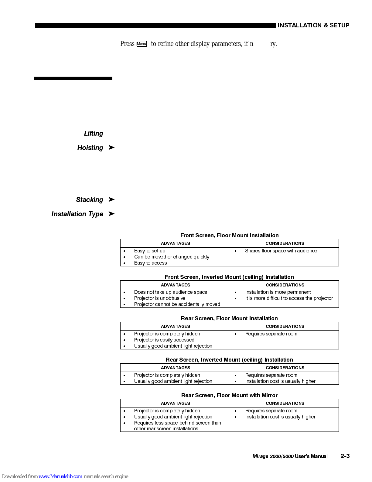
Choose the installation type which suits your needs: front or rear screen, floor mount
or inverted mount.
)URQW 6FUHHQ )ORRU 0RXQW ,QVWDOODWLRQ
$'9$17$*(6 &216,'(5$7,216
x
(DV\ WR VHW XS
x
&DQ EH PRYHG RU FKDQJHG TXLFNO\
x
(DV\ WR DFFHVV
x
6KDUHV IORRU VSDFH ZLWK DXGLHQFH
)URQW 6FUHHQ ,QYHUWHG 0RXQW FHLOLQJ ,QVWDOODWLRQ
$'9$17$*(6 &216,'(5$7,216
x
'RHV QRW WDNH XS DXGLHQFH VSDFH
x
3URMHFWRU LV XQREWUXVLYH
x
3URMHFWRU FDQQRW EH DFFLGHQWDOO\ PRYHG
x
,QVWDOODWLRQ LV PRUH SHUPDQHQW
x
,W LV PRUH GLIILFXOW WR DFFHVV WKH SURMHFWRU
5HDU 6FUHHQ )ORRU 0RXQW ,QVWDOODWLRQ
$'9$17$*(6 &216,'(5$7,216
x
3URMHFWRU LV FRPSOHWHO\ KLGGHQ
x
3URMHFWRU LV HDVLO\ DFFHVVHG
x
8VXDOO\ JRRG DPELHQW OLJKW UHMHFWLRQ
x
5HTXLUHV VHSDUDWH URRP
5HDU 6FUHHQ ,QYHUWHG 0RXQW FHLOLQJ ,QVWDOODWLRQ
$'9$17$*(6 &216,'(5$7,216
x
3URMHFWRU LV FRPSOHWHO\ KLGGHQ
x
8VXDOO\ JRRG DPELHQW OLJKW UHMHFWLRQ
x
5HTXLUHV VHSDUDWH URRP
x
,QVWDOODWLRQ FRVW LV XVXDOO\ KLJKHU
5HDU 6FUHHQ )ORRU 0RXQW ZLWK 0LUURU
$'9$17$*(6 &216,'(5$7,216
x
3URMHFWRU LV FRPSOHWHO\ KLGGHQ
x
8VXDOO\ JRRG DPELHQW OLJKW UHMHFWLRQ
x
5HTXLUHV OHVV VSDFH EHKLQG VFUHHQ WKDQ
RWKHU UHDU VFUHHQ LQVWDOODWLRQV
x
5HTXLUHV VHSDUDWH URRP
x
,QVWDOODWLRQ FRVW LV XVXDOO\ KLJKHU
 ,QVWDOODWLRQ
&RQVLGHUDWLRQV
/LIWLQ
J

+RLVWLQ
J

6WDFNLQ
J

,QVWDOODWLRQ 7
\S
H

,167$//$7,21 $1' 6(783

0LUDJH 
8VHU·V 0DQXDO
)URQW 6FUHHQ ,QVWDOODWLRQV
While there are two basic screen types, flat and curved, generally flat screens are
recommended for this projector. Flat screens offer a gain of about 1 with a viewing
angle just less than 180°. Incident light reflects equally in all directions so the
audience can see the display from various angles. Because of the low gain, flat
screens are most effective when ambient lighting is reduced, although this difference
may be negligible given the high brightness output from this projector.
)LJXUH  $XGLHQFH &RYHUDJH ZLWK )ODW 6FUHHQ
NOTE: Lenses for this projector are designed primarily for use with flat screens, but
the projector depth-of-field range allows the lens to be focused on curved screens as
well. While focus remains sharp in the corners, there may be significant pincushion
distortion, primarily at the top of the screen.
5HDU 6FUHHQ ,QVWDOODWLRQV
There are two basic types of rear screens: diffused and optical. A diffused screen has
a surface which spreads the light striking it. Purely diffused screens have a gain of
less than 1. The main advantage of the diffused screen is its wide viewing angle,
similar to that of a flat screen for front screen projection. Optical screens take light
from the projector and redirect it to increase the light intensity at the front of the
screen. This reduces it in other areas. A viewing cone, similar to that of a curved
front screen installation, is created.
To summarize, optical screens are better suited for brightly lit rooms where the
audience is situated within the viewing cone. Diffused screens may be better suited
when a wide viewing angle is required but there is low ambient room lighting.
Screen size may be from 5 to 40 feet diagonal, depending on the lens you are using.
For instance, a 1.2:1 lens can produce a 5 to 25 foot image size, whereas a 4-7:1
zoom lens produces an 8 to 40 foot image size. Choose a screen size which is
appropriate for your lens and application. Keep in mind that if the projector will be
used to display text information, the image size must allow the audience to recognize
all text clearly. The eye usually recognizes text clearly if eye-to-text distance is less
than 150 times the height of the letter. Small text located too far from the eye may be
illegible at a distance no matter how sharply and clearly it is displayed.
To fill a screen with an image, the aspect ratio of the screen should be equal to the
aspect ratio of the image. The aspect ratio of an image is expressed as the ratio of its
width to its height. Standard video from a VCR has a 4:3 aspect ratio. For example,
6FUHHQ 7
\S
H

6FUHHQ 6L]H

,167$//$7,21  6(783
0LUDJH 
8VHU·V 0DQXDO

to display a VCR output with a 4:3 aspect ratio onto a 10 foot (3m) high screen, the
width of the screen must be at least 13.3 feet (4m).
Aspect ratio describes the proportion of the screen and is expressed as the ratio of
width to height, such as “4:3”or “5:4”(see right). Although image size and image
aspect ratio can both be adjusted quickly through projector software, it is still a good
idea to choose a screen aspect ratio which is most appropriate for your intended
applications. Ideally, to exactly fill a screen with an image, the aspect ratio of the
screen should correspond to the aspect ratio of the image, which depends on the
source in use. For example, standard video from a VCR has a 4:3 ratio
(approximately), whereas a high resolution graphics signal typically has a 5:4 aspect
ratio. By default, images from your projector will be as large as possible and, with
the exception of graphics sources, will maintain their aspect ratio.
NOTE: With a few exceptions, sources with less than 1280 x 1024 resolution have a
4:3 aspect ratio. The normal aspect ratio for 1280 x 1024 sources is 5:4.
8VLQJ D  6FUHHQ
With one exception, XGA images will—
by default—resize to fill an SXGA (5:4)
screen. The exception is that video signals
will retain their aspect ratio, as shown in
Figure 2.3. In this case, fill the screen by
increasing Vertical Stretch to slightly
expand the image to the top and bottom
edges of the screen. For details, see 3.6,
Adjusting the Image.
8VLQJ D  6FUHHQ
If you are using a 4:3 screen (but producing 5:4 images), images will—by default—
slightly overlap the screen vertically. To remedy, reduce Vertical Stretch so that the
“too tall”5:4 image no longer spills over the top or bottom of the screen (Figure 2.4).
This control eliminates the need for simply moving the projector farther from the
screen, which would result in black borders for all sources. See 3.6, Adjusting the
Image.
NOTE: The Vertical Stretch adjustment may soften the image slightly, but is not
noticeable in most cases.
)LJXUH  8VLQJ D  6FUHHQ IRU D PL[ RI  DQG  VRXUFHV
6FUHHQ $V
S
HFW 5DWLR

)LJXUH  $GMXVWLQJ D  9LGHR
,PDJH
,167$//$7,21 $1' 6(783

0LUDJH 
8VHU·V 0DQXDO
The high brightness output of this projector is certainly well suited for locations
where ambient lighting is less than optimum for projection, yet there are still many
simple things you can do to optimize your installation.
Visiting a movie theater can give you an idea of what makes an ideal projection
environment. Walls, floors and furnishings are dark and matte finished. A projection
room should not have white reflective ceilings or non-directional lighting such as
fluorescent lights. The white ceiling spreads light, making the room appear brighter.
Keep lighting and reflections to a minimum.
If it is not possible to eliminate fluorescent lights, consider using incandescent spot
lighting or parabolic reflectors ("egg crates") to direct light down to the floor. Light
dimmers or rheostats allow further control.
Outside windows are undesirable in any projection room. A small crack between
curtains on a sunny day can wash out a projected image. If you do have windows,
make sure that window coverings are opaque and overlapping —some window
coverings are designed to provide up to 100 percent blockage of outside light.
Ideally, the material should have a matte finish.
To minimize the effects caused by unwanted light from door and aisle ways,
carefully choose the position of your projector and screen. Figure 2.5 shows an
installation where poor screen placement allows too much unwanted light to enter the
screen. In Figure 2.6, screen and the projector are positioned so that unwanted light is
minimized.
)LJXUH  3RRU 6FUHHQ 3ODFHPHQW
,GHDO 5RRP /L
J
KWLQ
J

,167$//$7,21  6(783
0LUDJH 
8VHU·V 0DQXDO

)LJXUH  %HWWHU 6FUHHQ 3ODFHPHQW
Even with all lighting removed it is still possible that room reflections within the
room can slightly degrade the image. Light from the projection screen should be
absorbed by the ceilings, walls and floors so that it will not be reflected back to the
screen. Again, keep reflective surfaces to a minimum.
Here are some other considerations and tips which can help you improve your
installation:
x
Ventilation is an important factor when preparing a projection room. The ambient
temperature should be kept constant and below 35°C (95°F). Keep the projector
away from heating and/or air conditioning vents. Changes in temperature can
cause drifts in the projector circuitry which may affect performance.
x
Keep the projector away from devices which radiate electromagnetic energy such
as motors and transformers. Common sources of these are slide projectors,
speakers, power amplifiers, elevators, etc.
x
For rear screen applications, less space is required if a mirror is used to fold the
optical path.
x
Choose the right screen size for the application:
¡
As screen size increases, magnification increases and reduces brightness.
Select a screen size which is appropriate for the venue, but not larger
than that required.
¡
Installing a large screen in a small room is similar to watching television
close up; too large a screen can overpower a room. A good rule of thumb
is to be no closer than 1.5 times the width of the screen.
¡
Larger screens require greater attention to lighting conditions.
x
When laying out the projection room, consider positioning the projector and
screen in a manner which will achieve maximum audience coverage and space
efficiency. For example, placing the screen along the larger wall in a rectangular
room will reduce audience coverage. Figure 2.7 shows two examples of how
audience coverage is maximized.
2WKHU &RQVLGHUDWLRQV

,167$//$7,21 $1' 6(783

0LUDJH 
8VHU·V 0DQXDO
)LJXUH  6FUHHQ /RFDWLRQV IRU 0D[LPXP $XGLHQFH &RYHUDJH
Installation type, screen type, and lighting all affect where the projector is positioned.
In addition, both throw distance (the distance between the projector and screen) and
vertical position (the height of the projector in relation to the screen) must be
determined for every new installation. Both depend on the screen size and lens type
you are using. Make sure that the room can accommodate the required position of the
projector for the chosen screen size.
Throw distance is the distance between the projector's front feet and the screen. For
any installation, an accurate throw distance must be determined in order for the
image to be of the right size for your screen–the farther the projector is from the
screen, the larger the image.
NOTE: If your projector is tilted in relation to the screen, as is sometimes the case
for large venues or elevated installations, throw distance still represents the smallest
measurement between the screen and front feet.
Throw distance is roughly equal
to the horizontal width of the
screen multiplied by the type of
lens you are using. For example,
if you are using a 0.8:1 lens,
proper throw distance will be
approximately 0.8
[
the screen
width. Once you know your
screen size and lens, you can
estimate throw distance needed
(see example in Figure 2.8).
,03257$17
For proper
placement in an installation,
always refer to the throw distance formula and/or graph for your lens as listed in
Appendix E. Keep in mind that due to lens manufacturing tolerances for lens focal
length, actual throw distance can vary ±5% between lenses described as having the
same throw ratio.
 3URMHFWRU
3RVLWLRQDQG
0RXQWLQJ
7KURZ 'LVWDQFH

)LJXUH  (VWLPDWLQJ 7KURZ 'LVWDQFH
6(( $33(1',; (