manuals.online logo
Brands
  1. Home
  2. •
  3. Brands
  4. •
  5. Chroma
  6. •
  7. Light Fixture
  8. •
  9. Chroma Color Block 2 User manual

Chroma Color Block 2 User manual

Chroma-Q™
Color Block 2™
User Manual
Version 1.1 September 2012
PN: 603-0500
Color Block 2 User Manual 1 V1.1 Septe ber 2012
www.chroma
-
q.com
Warranty Statement
Chro a-Q warrants to the original purchaser, with proof of purchase, that its delivered products shall be free fro defects in
aterial and work anship under nor al use for a period of 12 onths fro date of ship ent.
Chro a-Q will repair, or at its option, provide an equivalent ite or replace, the defective product during the stated warranty
period. This warranty applies only to the repair or replace ent of the product and only when the product is properly handled,
installed and aintained according to Chro a-Q instructions. This warranty excludes defects resulting fro i proper
handling, storage, installation, acts of God, fire, vandalis or civil disturbances. Purchaser ust notify Chro a-Q in writing
within 14 days of noticing the defect. This warranty excludes field labour or service charges related to the repair or
replace ent of the product.
The warranty contained herein shall not extend to any finished goods or spare parts fro which any serial nu ber has been
re oved or which have been da aged or rendered defective (a) as a result of nor al wear and tear, willful or accidental
da age, negligence, isuse or abuse; (b) due to water or oisture, lightning, windstor , abnor al voltage, har onic
distortion, dust, dirt, corrosion or other external causes; (c) by operation outside the specifications contained in the user
docu entation; (d) by the use of spare parts not anufactured or sold by Chro a-Q or by the connection or integration of
other equip ent or software not approved by Chro a-Q unless the Custo er provides acceptable proof to Chro a-Q that
the defect or da age was not caused by the above; (e) by odification, repair or service by anyone other than Chro a-Q,
who has not applied for and been approved by Chro a-Q to do such odification, repair or service unless the Custo er
provides acceptable proof to Chro a-Q that the defect or da age was not caused by the above; (f) due to procedures,
deviating fro procedures specified by Chro a-Q or (g) due to failure to store, install, test, co ission, aintain, operate or
use finished goods and spare parts in a safe and reasonable anner and in accordance with Chro a-Q’s instructions (h) by
repair or replace ent of engines without factory training.
The warranty contained herein shall not apply to finished goods or spare parts which are sold “as is”, as “second-hand”, as
used”, as “de o” or under si ilar qualifications or to Consu ables (“Consu ables” is defined as any part(s) of goods or
part(s) for use with goods, which part(s) of goods or part(s) for use with goods are consu ed during the operation of the
goods and which part(s) of goods or part(s) for use with goods require replace ent fro ti e to ti e by a user such as, but
not li ited to, light bulbs).
The warranty contained herein shall not apply, unless the total purchase price for the defective finished goods or spare parts
has been paid by the due date for pay ent.
The warranty contained herein applies only to the original purchaser and are not assignable or transferable to any
subsequent purchaser or end-user.
This warranty is subject to the ship ent of the goods, within the warranty period, to the Chro a-Q warranty returns
depart ent, by the purchaser, at the purchasers expense. If no fault is found, Chro a-Q will charge the purchaser for the
subsequent return of the goods.
Chro a-Q reserves the right to change the warranty period without prior notice and without incurring obligation and
expressly disclai s all warranties not stated in this li ited warranty.
Color Block 2 User Manual 2 V1.1 Septe ber 2012
www.chroma
-
q.com
Disclaimer
The infor ation contained herein is offered in good faith and is believed to be accurate. However, because conditions and
ethods of use of our products are beyond our control, this infor ation should not be used in substitution for custo er's
tests to ensure that A.C. Entertain ent Technologies Ltd. products are safe, effective, and fully satisfactory for the intended
end use. Suggestions of use shall not be taken as induce ents to infringe any patent. A.C. Entertain ent Technologies Ltd.
sole warranty is that the product will eet the sales specifications in effect at the ti e of ship ent. Your exclusive re edy
for breach of such warranty is li ited to refund of purchase price or replace ent of any product shown to be other than as
warranted.
A.C. Entertain ent Technologies Ltd. reserves the right to change or ake alteration to devices and their functionality
without notice due to our on going research and develop ent.
The Chro a-Q™ Color Block 2™ syste has been designed specifically for the lighting industry. Regular aintenance
should be perfor ed to ensure that the products perfor well in the entertain ent environ ent.
If you experience any difficulties with any Chro a-Q products please contact your selling dealer. If your selling dealer is
unable to help please contact sup[email protected] . If the selling dealer is unable to satisfy your servicing needs, please
contact the following, for full factory service:
utside North America: North America:
A.C. Entertain ent Technologies Ltd. A.C. Lighting Inc.
Centauri House Unit #1
Hillbotto Road, 435 Horner Avenue,
High Wyco be, Toronto,
Buckingha shire, ON.
HP12 4HQ. M8W 4W3
United Kingdo Canada
Tel: +44 (0)1494 446000 Tel: 416-255-9494
Fax: +44 (0)1494 461024 Fax: 416-255-3514
For further infor ation please visit the A.C. Entertain ent Technologies website at
www.ac-et.co .
Chro a-Q and Color Block 2 are trade arks of A.C. Entertain ent Technologies Ltd.
The rights and ownership of all trade arks are recognised.
Color Block 2 User Manual 3 V1.1 Septe ber 2012
www.chroma
-
q.com
Table of Contents
1. Product verview ……………...…………………………………………………….………... 4
1.1 Chro a-Q Color Block 2 …………………………………………………………. 4
1.2 Chro a-Q Color Block Power Supply Units ………………………………….…………. 5
2. peration ……………...…………………………………………………….………... 5
2.1 Unpacking the units …………………………………………………………. 5
2.2 Cabling ……………………………………………….…………. 5
2.3 Fixings ……………………………………………….…………. 6
2.4 Control ……………………………………………….…………. 9
3. Troubleshooting ……………...…………………………………………………….………... 11
4. Specification ……………...…………………………………………………….………... 12
4.1 Technical specifications …………………………………………………………. 12
4.2 Photo etric Perfor ace …………………………………………………………. 13
4.3 Drawings …………………………………………………………. 14
5. Maintenance ……………...…………………………………………………….………... 15
6. Accessories ……………...…………………………………………………….………... 15
Color Block 2 User Manual 4 V1.1 Septe ber 2012
www.chroma
-
q.com
1. Product overview
1.1 Chroma-Q Color Block 2
Following the enor ous success of the Chro a-Q Color Block™ LED fixture with rental co panies and end users alike, the
anufacturer has co bined the product's core ele ents of odularity and versatility with new single color RGBA optics, 530
lu ens output (al ost double the original odel) and theatrical grade di ing to create the exceptional feature set of the
Color Block 2 fixture.
With its radically increased color palette and high CRI of 90, the Color Block 2 fixture is a aster at creating vibrant bold
colors and subtle theatrical hues. Co bined with its built-in variable color te perature capability, even flesh tones look
natural, satisfying all but the ost critical eye.
The four large, ca era-friendly LED cells offer perfor ers less glare and ix beautifully for single color output, virtually
eli inating the frustrating color separation shadows nor ally synony ous with LED lighting. The bea optics have a soft
asy etrical quality carefully crafted to give an i ediate perfect color blend for uplighting surfaces, yet retain a soft
Fresnel-like edge for direct illu ination. At close to twice the output of its predecessor, the Color Block 2 fixture is bright
enough to uplight a 6 / 20 foot set and then so e
.
Each Color Block 2 fixture features 48 high output LED set into 12 single optic RGBA clusters that are grouped into 4 cells
which produce an intense, powerful light and vibrant colours across the spectru .
The control options incorporate a choice of HSI (Hue, Saturation and Intensity), RGBA (Red, Green, Blue, A ber), RGB(A)
(Red, Green, Blue, with *Magic A ber), RGBI (Red, Green, Blue with *Magic A ber and Intensity) control odes, and a
dyna ic Variable Effects Engine integrated in the software which gives the lighting designer full control over colour and
effects co binations.
The product's lightweight yet robust, heavy gauge alu iniu extruded construction houses a discreet cable anage ent
syste and additional protection is built around the LED lenses for a truly road proof fixture.
A range of DMX controlled power supplies are available to acco odate ost applications. Each Color Block Power Supply
features XLR4 outputs with a axi u capacity of 5 Color Block 2 fixtures daisy chained together. See separate PSU user
anual for control details.
* Magic A ber is the ter used for the unit's ability to bring in A ber when ixing colors that require it
Color Block 2 User Manual 5 V1.1 Septe ber 2012
www.chroma
-
q.com
1.2 Chroma-Q Color Block Power Supply Units
Two DMX controlled power supply odels are available to acco odate ost applications or operate independently as a
standalone syste . Each Color Block Power Supply features outputs via XLR4. The unit can be controlled re otely via ANSI
E1.11 USITT DMX 512-A (XLR-5 pin).
The Color Block PSU-05B delivers power and data via 1 XLR4 output. A axi u of five daisy-hained Color Block 2 fixtures
can be connected to the PSU-05B. Return lines are not required. The total cable length of each chain ust not exceed
60 /200ft. Two in/out ethernet RJ45 connectors are available for synchronisation.
The Color Block PSU-30 delivers power and data via 6 XLR4 outputs. A axi u of five daisy-chained Color Block 2 fixtures
can be connected to each XLR4 output. Return lines are not required. The total cable length of each chain ust not exceed
60 /200ft. Two in/out ethernet RJ45 connectors are available for synchronisation.
2. peration
2.1 Unpacking the units
The Color Block 2 package includes 1 unit Color Block 2 fixture and a Quick Start Guide. We reco end that you keep the
original packaging in case ite needs to be returned.
2.2 Cabling
The Color Block 2 syste utilises an XLR 4-pin cable syste . This is used to supply power and control data. Pin 1 = 0VDC,
pin 2 = control inus, pin 3 = control plus, pin 4 = +48VDC. The drain wire should be connected to the chassis of the XLR.
Pin # Pin # Minimum Cable size
1 Ground (-ve) 2.50 ² (14 AWG)
2 Control data inus (-) 0.35 ² (22 AWG)
3 Control data plus (+) 0.35 ² (22AWG)
4 24V DC (+ve) 2.50 ² (14 AWG)
Chassis Cable shield/drain wire 0.25 ² (24 AWG)
Only genuine Tourflex Datasafe cable is reco ended for use with the Color Block 2 syste . Da age will occur if power
connections short-circuit to data or ground shield connections. When asse bling XLR4-pin cables, heat shrink should be
used on each individual data pin and the drain wire to prevent short circuits.
Color Block 2 User Manual 6 V1.1 Septe ber 2012
www.chroma
-
q.com
The Color Block 2 power supplies deliver power and data via XLR4. A axi u of five daisy-chained Color Block 2 fixtures
can be connected to one cable. Return lines are not required. The total cable length of each chain ust not exceed 60
eters (200ft).
It is reco ended that a axi u of 20 XLR4 cable length should separate adjacent units as to avoid signal
deterioration.
Note:
Maxi u of 5 Color Block 2 fixtures per cable. No return cables required.
2.3 Fixings
One of the strengths of the Color Block 2 fixture is its flexible fixing possibilities. The Color Block 2 fixture is supplied with an
integral M10 clinch nuts at each end. These can be used to attach the Color Block 2 fixture to a standard hook cla p or the
wide range of Color Block accessories listed below.
Note: Da age ay occur if the bolt is too long (M10x16 axi u ). In addition, both sides of the fixture feature a fixing slot
designed to accept an M6 bold head.
The Color Block 2 fixture also features an integral connection syste to enable up to five units to be locked together as a
batten (see below).
Note: it is i portant to ensure that each fixture is also secured with a safety bond. The end plate of each fixture has a fixing
hold to facilitate secondary fixings.
a. Integrated connection system
One end of the Color Block 2 fixture features two protruding locating pins and a catch plate, the other end has two keyhole
slots and a butterfly latch.
1. To connect two fixtures together, firstly ate the two protruding pins fro one fixture into the keyhole slots of the other.
Color Block 2 User Manual 7 V1.1 Septe ber 2012
www.chroma
-
q.com
2. Then slide the fixtures together so that they are aligned correctly, taking care to get past the extended catch plate.
Note: This will be stiff on new fixtures and a twisting action ay ease asse bly.
3. Finally use the butterfly latch to secure the fixtures together tightly ( ax 5 units together).
Note: It is i portant to ensure adequate ventilation to the rear of all Color Block fixtures. Never place the fixtures directly on
the floor pointing upwards when configured as a batten.
The Color Block 2 fixture is supplied with an integral M10 clinch nuts at each
end. These can be used to attach the Color Block 2 fixture to a standard hook
cla p.
Note: da age ay occur if the bolt is too long. (M10x16 axi u )
b. Batten bracket kit for up to five fixtures
The batten bracket set is supplied as a pair of brackets with fibre washers and thu b wheels.
The batten bracket set can be used for floor ounting (see photo), direct wall ounting and truss ounting when used in
conjunction with hook cla ps or half couplers.
Color Block 2 User Manual 8 V1.1 Septe ber 2012
www.chroma
-
q.com
c. Yoke kit for single fixture
The yoke kit for single fixture is supplied as a yoke bracket with fibre washers and thu b wheels.
The yoke kit can be used for floor ounting (see photo), direct wall ounting and truss ounting when used in conjunction
with hook cla ps or half couplers.
d. Dual mode yoke kit for single fixture
The dual ode yoke kit for single fixture is supplied with fibre washers and thu b wheels. The dual ode yoke co bines the
function of the single yoke and the batten bracket.
e. Blinder frame for four fixtures
The blinder fra e is supplied as a yoke bracket, side plates, fibre washers, thu b wheels and eight M10 bolts.
The blinder fra e is designed to truss ount with the use of a half coupler.
The end plates feature two co plete sets of fixture fixing holes. Set one hold the fixtures closely together ensuring equal
centres for all sixteen cells. Sets two are adjustable and allow the Color Block 2 fixtures to be splayed out at varying angles.
f. Hinge kit
The hinge kit is supplied as one co plete hinge with fibre washers and M10 bolts.
The hinge kit fits between two Color Block 2 fixtures and offers an angle adjust ent of 180 deg. If used in ultiples, unique
shapes can be achieved, such as hexagons, octagons etc.
Color Block 2 User Manual 9 V1.1 Septe ber 2012
www.chroma
-
q.com
g. Wall bracket for single fixture
The Wall bracket for single fixture is a discreet fixing suitable for fixing a single Color Block 2 to a wall or set piece. Keyhole
slots are provided to for vertical or horizontal fixing.
2.4 Control
The Chro a-Q Color Block 2 is controlled via two odels of addressable ANSI E1.11 USITT DMX512-A power supply units,
the 5 way Color Block PSU-05B and the 30 way Color Block PSU-30.
The Color Block power supply units can be set to operate in 16 odes by selecting “CB2” under “Syste ” in the control
enu. Single cell, block-grouped and all-grouped outputs are available in 5 control options: HSIFX, HSI, RGBA, RGB (with
*Magic A ber), RGBI (with *Magic A ber), pre-progra ed looks and standalone effects. See relevant power supply user anual for full details.
Color Block PSU-05B Power Supply
Mode Channel Group Description
1
67 Variable by Ch 1 7FX + 20 x HSI
2 60 Cell 20 x HSI
3 60 Cell 20 x RGB (with *Magic A ber)
4 21 Block 6FX + 5 x HSI
5 15 Block 5 x HSI
6 15 Block 5 x RGB (with *Magic A ber)
7 9 All 6FX + HS
8 3 All HSI
9 3 All RGB (with *Magic A ber)
10 80 Cell 20 x RGBA
11 80 Cell 20 x RGBI (with *Magic A ber)
12 20 Block 5 x RGBA
13 20 Block 5 x RGBI (with *Magic A ber)
14 4 All RGBA
15 4 All RGBI (with *Magic A ber)
16 1 Any Look Select
Color Block 2 User Manual 10 V1.1 Septe ber 2012
www.chroma
-
q.com
Color Block PSU-30 Power Supply
Mode Channel Group Description
1
367 Variable by Ch 1 7FX + 120 x HSI
2 360 Cell 120 x HSI
3 360 Cell 120 x RGB (with *Magic A ber)
4 96 Block 6FX + 30 x HSI
5 90 Block 30 x HSI
6 90 Block 30 x RGB (with *Magic A ber)
7 9 All 6FX + HSI
8 3 All HSI
9 3 All RGB (with *Magic A ber)
10 480 Cell 120 x RGBA
11 480 Cell 120 x RGBI (with *Magic A ber)
12 120 Block 30 x RGBA
13 120 Block 30 x RGBI (with *Magic A ber)
14 4 All RGBA
15 4 All RGBI (with *Magic A ber)
16 1 Any Look Select
Control ptions
3 channel HSI
(Hue, Saturation and Intensity) gives 2 colour channels for hue and saturation and a separate intensity
channel. A separate definable intensity channel is particularly useful when creating intensity chases or when the grand
aster is used. The hue channel has 255 different colours available and the saturation channel specifies the saturation level
of that colour. The saturation channel is fully saturated at full. White is achieved with the intensity channel to full and the
saturation channel at zero.
3 channel RGB
(Red, Green, Blue with *Magic A ber) is the ore traditional way of controlling colour changing LED fixtures.
Each of the three control channels directly affects the intensity of the corresponding LED. Colour is ixed by adjusting the
levels of the three pri ary colours. White is achieved with all channels at full including *Magic A ber.
3 channel RGB(A) + 1 intensity channel
(Red, Green, Blue with *Magic A ber and Intensity) gives 3 control channels
directly affecting the intensity of the corresponding LED – Red, Green, Blue with *Magic A ber, and 1 channel affecting the
intensity of all RGB(A) channels.
4 channel RGBA (Red, Green, Blue and A ber) gives 4 control channels directly affecting the intensity of the corresponding
LED – Red, Green, Blue and A ber. Color is ixed by adjusting the levels of each of the four colors. White is achieved with
all channels at full.
Internal FX engine:
odes 1, 4, and 7 incorporate a co prehensive internal FX engine with seven variable para eters to
create an unli ited a ount of unique lighting effects.
Descriptions for the effects channels included in the following odes:
Color Block 2 User Manual 11 V1.1 Septe ber 2012
www.chroma
-
q.com
Mode 1:
Ch1 – Grouping, variable grouping facility to run FX / within groups
Ch2 – Colour Speed, variable speed of colour scrolling
Ch3 – Colour Fan, variable fan of colour between / within groups
Ch4 – Colour Range, variable li it of spectru range for colour scrolling
Ch5 – Colour Step, variable control of s oothness of colour scrolling
Ch6 – Intensity Effects, wide selection of intensity fading and snapping effects
Ch7 – Intensity Fan, variable fan of intensity effects
Mode 4 and 7:
Ch1 – Colour Speed, variable speed of colour scrolling
Ch2 – Colour Fan, variable fan of colour between / within groups
Ch3 – Colour Range, variable li it of spectru range for colour scrolling
Ch4 – Colour Step, variable control of s oothness of colour scrolling
Ch5 – Intensity Effects, wide selection of intensity fading and snapping effects
Ch6 – Intensity Fan, variable fan of intensity effects
All internal FX are referenced back to the group base HSI colour and intensity levels.
* Magic A ber is the ter used for the unit's ability to bring in A ber when ixing colors that require it.
3. Troubleshooting
Troubleshooting is a process of eli ination. First, rule out the other field factors (i.e. bad connections, faulty cables and
power supplies). For technical advice and/or parts, please contact your selling dealer or the offices listed in this anual.
Symptom Possible Cause Solution
Fixture does not respond to DMX control. PSU set to wrong or different DMX
address.
Bad cable connecting DMX control
and PSU.
Bad cable connecting PSU and the
fixture.
Bad in/thru connection between
adjacent fixtures.
Fan not working.
Check DMX address and Mode
settings.
Check/replace DMX run fro the
console.
Check/replace cable fro PSU to
fixture or in/thru connections.
Call selling dealer if fan is not
working.
Intensity levels of LED are fluctuating. Signal deterioration, cable lengths
connecting adjacent fixtures are too
long.
Check the cable length and
configuration.
Fixture does not respond to DMX control but
PSU and all cable connection are good.
Electronics fault in the fixture unit. Call selling dealer.
Noise fro fixture unit. Fan alfunction. Check fan and call selling dealer.
Color Block 2 User Manual 12 V1.1 Septe ber 2012
www.chroma
-
q.com
4. Specification
4.1 Technical specifications
Product Code: CHCB4M2
Di ensions: 250 x 62 x 117
9.8" x 2.4" x 4.6"
Weight: 1.3kg / 2.8lbs
Power input rating: 48V DC
Control protocol: ANSI E1.1 DMX-512A
Connector in/out: XLR4
Maxi u cable run: 60 / 200’
Cooling syste : 1 x fan
Construction: Anodised alu iniu extrusion
Colour: Black
LED cells: 4
LED per cell: 12 RGBA
Total LED: 48
Optics: Specialised close focus lens
Bea angle: 25º (approx.)
Bea dispersion: Sy etrical direct illu ination
CCT: Adjustable 1000 – 10000K
La p life: L70 up to 50,000 hours
Operating te perature: 0ºC to +40ºC
IP rating: IP20
Approvals: EN55103-1, EN55103-2, IEC60950
Color Block 2 User Manual 13 V1.1 Septe ber 2012
www.chroma
-
q.com
4.2 Photometric Performance
Photometric data for colour white Photometric data for colour red
3’/1m 6’/2m 9’/3m 12’/4m 15’/5m 3’/1m 6’/2m 9’/3m 12’/4m 15’/5m
FC 182 49 23 14 8
FC 86 23 11 6 4
Lux 1960 526 246 146 88
Lux 930 247 15 68 41
Photometric data for colour green Photometric data for colour blue
3’/1m 6’/2m 9’/3m 12’/4m 15’/5m 3’/1m 6’/2m 9’/3m 12’/4m 15’/5m
FC 152 41 19 11 7
FC 18 5 2 1 1
Lux 1637 438 203 117 76
Lux 192 51 24 14 9
Photometric data for colour amber
3’/1m 6’/2m 9’/3m 12’/4m 15’/5m
FC 88 24 10 7 4
Lux 952 253 110 72 41
Light utput
Color White Red Green Blue A ber
utput 532 266 445 56 242
Color Block 2 User Manual 14 V1.1 Septe ber 2012
www.chroma
-
q.com
4.3 Drawings
Color Block 2 User Manual 15 V1.1 Septe ber 2012
www.chroma
-
q.com
5. Maintenance
With care, the Color Block 2 fixture will require little aintenance. However, as the unit is likely to be used in a stage
environ ent we reco end periodical internal inspection and cleaning of any resulting dust and cracked oil residue.
Do not spray liquids on the front or rear panel. If the front enclosure requires cleaning, wipe with a ild detergent on a da p
cloth.
6. Accessories
Model Part No
Chro a-Q PSU for up to 5 Color Block units CHCBPSU05
Chro a-Q PSU for up to 30 Color Block units CHCBPSU30
Yoke kit for single Color Block CHCBSY
Dual ode yoke kit for single Color Block CHCBCY
Batten bracket kit for up to 5 Color Block units CHCBBB
Blinder fra e for 4 Color Block units CHCBBF4
Hinge kit for Color Block CHCBHP
Wall bracket for single Color Block CHCBWB
LED pipe for Color Block 1.3 / 4’ (5-way batten) CHCBLP1300
LED pipe for Color Block 0.25 / 9.8” (single) CHCBLP250
Single link cable for use in batten for at MUCX4SDP-0.22
Other cable lengths available (‘x’ is length in ) MUCX4SDP-X
LED Pipe
The LED pipe is available in 250 and 1300 lengths and si ply snaps
into the fixing slots on the fixture body. The LED pipe blends and diffuses the
RGBA LED output of adjacent cells, taking the resulting colour. The LED pipe is
particularly effective at linear colour chase effects.

Other manuals for Color Block 2

2

This manual suits for next models

1

Other Chroma Light Fixture manuals

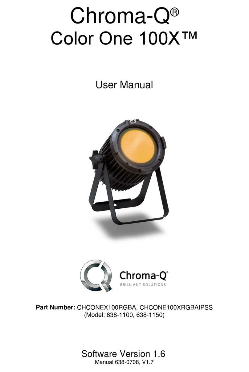
Chroma Color One 100 User manual

Chroma

Chroma Color One 100 User manual

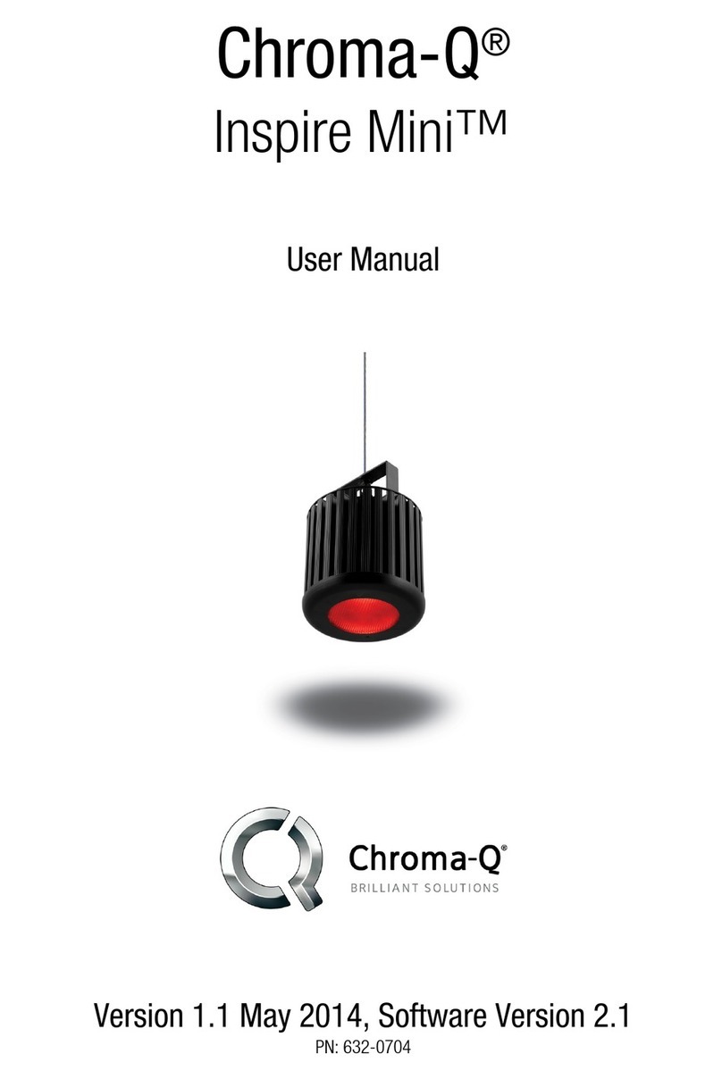
Chroma Inspire Mini User manual

Chroma

Chroma Inspire Mini User manual

Chroma Color One 100X User manual

Chroma

Chroma Color One 100X User manual

Chroma Inspire User manual

Chroma

Chroma Inspire User manual

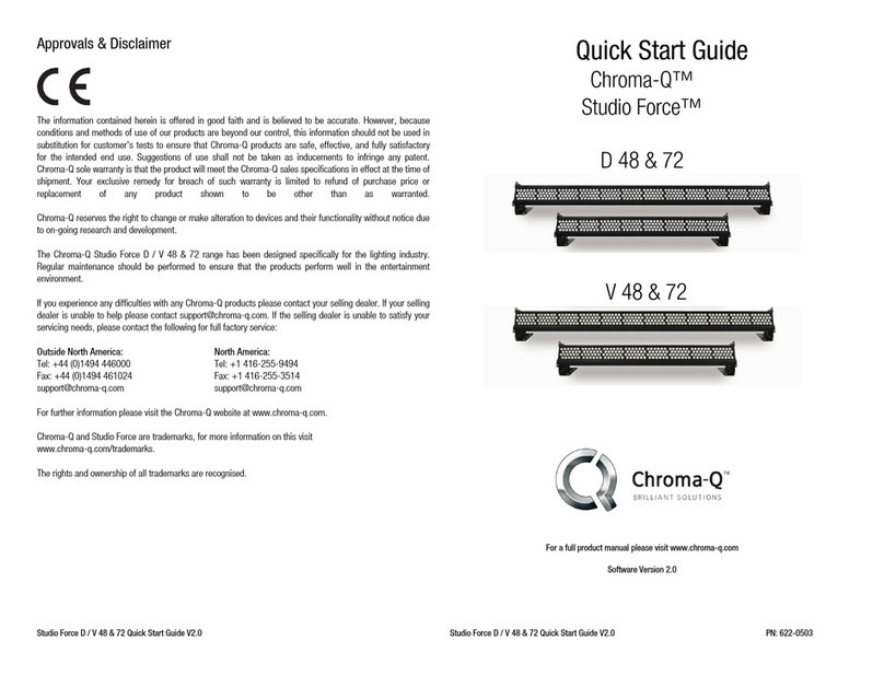
Chroma Studio Force D Compact User manual

Chroma

Chroma Studio Force D Compact User manual

Chroma Studio Force D 48 User manual

Chroma

Chroma Studio Force D 48 User manual

Chroma Space Force User manual

Chroma

Chroma Space Force User manual

Chroma Inspire User manual

Chroma

Chroma Inspire User manual

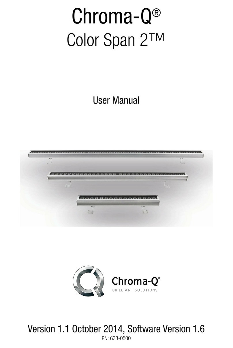
Chroma Color Span 2 User manual

Chroma

Chroma Color Span 2 User manual

Popular Light Fixture manuals by other brands

Verilux VT05 user manual

Verilux

Verilux VT05 user manual

EuroLite LED TMH-20 user manual

EuroLite

EuroLite LED TMH-20 user manual

Tungsram HighBay G2 Install Instruction Guide

Tungsram

Tungsram HighBay G2 Install Instruction Guide

ALPHA LITE FS Series user manual

ALPHA LITE

ALPHA LITE FS Series user manual

Ghost batly instruction manual

Ghost

Ghost batly instruction manual

Lightolier Lytecaster 604MR specification

Lightolier

Lightolier Lytecaster 604MR specification

Original BTC DAVEYLIGHTING 7679 instruction manual

Original BTC

Original BTC DAVEYLIGHTING 7679 instruction manual

Gama Sonic GS-6 instruction manual

Gama Sonic

Gama Sonic GS-6 instruction manual

Kichler Lighting 15735AZT installation instructions

Kichler Lighting

Kichler Lighting 15735AZT installation instructions

Lightolier 6700S2UEMNY specification

Lightolier

Lightolier 6700S2UEMNY specification

Lightolier Lytecaster 302ESICX specification

Lightolier

Lightolier Lytecaster 302ESICX specification

GE Lumination EP24 Series installation guide

GE

GE Lumination EP24 Series installation guide

Westinghouse W-350 owner's manual

Westinghouse

Westinghouse W-350 owner's manual

Philips 33259-31-16 user manual

Philips

Philips 33259-31-16 user manual

Lightolier QVH2GPFOS2FT specification

Lightolier

Lightolier QVH2GPFOS2FT specification

Lightolier Lytespan 8180WH specification

Lightolier

Lightolier Lytespan 8180WH specification

American DJ Mini Starball II User instructions

American DJ

American DJ Mini Starball II User instructions

RSA Lighting Combolight Galleria Series PAR38 120V specification

RSA Lighting

RSA Lighting Combolight Galleria Series PAR38 120V specification

manuals.online logo
manuals.online logoBrands
  • About & Mission
  • Contact us
  • Privacy Policy
  • Terms and Conditions

Copyright 2025 Manuals.Online. All Rights Reserved.