Puls dimension UB10.241 User manual

Read first ! English 1
Before operating this unit please read this manual thoroughly. Retain this manual for future reference! This device may only installed and put into operation by qualified personnel.
Intended Use:
This device is designed for installation in an enclosure and is intended for the general use such as in industrial control, office, communication, and instrumentation equipment. Do not use this device in
aircrafts, trains and nuclear equipment where malfunction may cause severe personal injury or threaten human life.
WARNING !
Risk of electrical shock, fire, personal injury or death.
(1) Turn power off before working on the device. Disconnect battery fuse.
(2) Make sure if the wiring is correct by following all local and national codes.
(3) Do not open, modify or repair the unit.
(4) Use caution to prevent any foreign objects from entering into the housing.
(5) Do not use in wet locations.
(6) Do not use the unit in area where moisture or condensation can be expected.
If damage or malfunction should occur during operation, immediately turn power off and send unit for inspection to the factory!
The information presented in this document is believed to be accurate and reliable and may change without notice. The English text applies in cases of doubt.
Notes for use in
hazardous locations
WARNING EXPLOSION HAZARDS
Units which are marked with "Class I Div 2" are suitable for use in non-hazardous or Class I Division 2 Groups A, B, C, D locations only.
Substitution of components may impair suitability for Class I Division 2 environment. Do not disconnect equipment unless power has been switched off.
Wiring must be in accordance with Class I, Division 2 wiring methods of the National Electrical Code, NFPA 70, and in accordance with other local or national codes.
Vor Inbetriebnahme lesen ! Deutsch 2
Bitte lesen Sie diese Warnungen und Hinweise sorgfältig durch bevor Sie das Gerät in Betrieb nehmen. Bewahren Sie die Anleitung zum Nachlesen auf. Das Gerät darf nur durch fachkundiges und
qualifiziertes Personal installiert werden.
Bestimmungsgemäßer Gebrauch:
Dieses Gerät ist für den Einbau in ein Gehäuse konzipiert und zur Verwendung für allgemeine elektronische Geräte, wie z.B. Industriesteuerungen, Bürogeräte, Kommunikationsgeräte oder
Messgeräte geeignet. Benutzen Sie dieses Gerät nicht in Steuerungsanlagen von Flugzeugen, Zügen oder atomaren Einrichtungen, in denen eine Funktionsstörung zu schweren Verletzungen führen
oder Lebensgefahr bedeuten kann.
WARNUNG !
Missachtung nachfolgender Punkte kann einen elektrischen Schlag, Brände, schwere Unfälle oder Tod zur Folge haben.
(1) Schalten Sie die Eingangsspannung vor Installations-, Wartungs- oder Änderungsarbeiten ab. Entfernen Sie die Batteriesicherung.
(2) Sorgen Sie für eine ordnungsgemäße und fachgerechte Verdrahtung.
(3) Führen Sie keine Änderungen oder Reparaturversuche am Gerät durch. Öffnen Sie das Gerät nicht.
(4) Verhindern Sie das Eindringen von Fremdkörpern.
(5) Betreiben Sie das Gerät nicht in feuchter Umgebung.
(6) Betreiben Sie das Gerät nicht in einer Umgebung, bei der mit Betauung oder Kondensation zu rechnen ist.
Bei Funktionsstörungen oder Beschädigungen schalten Sie sofort die Versorgungsspannung ab und senden das Gerät zur Überprüfung ins Werk.
Die angegebenen Daten dienen allein der Produktbeschreibung und sind nicht als zugesicherte Eigenschaften im Rechtssinne aufzufassen. Im Zweifelsfall gilt der englische Text.
Hinweise für den
Betrieb in
explosionsgefährdeter
Umgebung
ACHTUNG EXPLOSIONSGEFAHR !
Geräte, die am Leistungsschild mit "Class I Div 2" gekennzeichnet sind, sind für den Einsatz in Klasse I Division 2 Gruppen A,B,C,D oder für explosions-ungefährliche
Aufstellorte geeignet. Veränderungen an Bauteilen können die Tauglichkeit für Klasse I Division 2 beeinträchtigen. Anschlüsse nicht trennen solange Spannung anliegt.
Anschluss muss unter Berücksichtigung der Anforderungen nach Klasse I Division 2 Artikel 501-4(b) des National Electrical Code, NFPA 70 erfolgen.
A lire avant mise sous tension Français 3
Merci de lire ces instructions de montage et d'entretien avant de mettre l'alimentation sous tension. Conservez ce manuel qui vous sera toujours utile. Cette alimentation doit être installée par du
personnel qualifié et compétent.
Utilisation:
Cet appareil est conçu pour être installé dans une armoire et pour tous les équipements électroniques, tel que l'équipement industriel de commande, l'équipement de bureau, le matériel de
communication et les instruments de mesures. N'utilisez pas cet appareil pour l'équipement de commandes dans les avions, les trains et l'équipement atomique où un problème de fonctionnement
de l'alimentation pourrait causer des blessures graves ou menacer la vie humaine.
ATTENTION !
Prendre en compte les points suivants, afin d'éviter toute détérioration électrique, incendie, dommage aux personnes ou mort.
(1) ne jamais faire fonctionner l'alimentation sans raccordement à la terre ! Veuillez enlever le fusible de la batterie avant d’effectuer des modifications sur la batterie ou sur le DC-UPS.
(2) débrancher l'installation avant toute intervention sur l'alimentation (ou démontage) et s'assurer qu'il n'y a pas risque de redémarrage.
(3) s'assurer que le câblage a été fait selon les prescriptions
(4) ne pas effectuer de réparations ou modifications sur l'alimentation
(5) ne pas ouvrir l'appareil. Des tensions importantes passent à l'intérieur.
(6) veiller à ce qu'aucun objet ne rentre en contact avec l'intérieur de l'alimentation (trombones, pièces métalliques)
(7) ne pas faire fonctionner l'appareil dans un environnement humide ou à l'extérieur, non protégé
(8) ne pas utiliser l'appareil dans un environnement où il peut y avoir de la condensation.
Si un défaut quelconque apparaît en cours de fonctionnement, débrancher au plus vite l'alimentation. Dans ce deux cas de figure, il convient de faire contrôler l'alimentation en usine!
Les données indiquées dans ce document servent uniquement à donner une description du produit et n'ont aucune valeur juridique. En cas de divergences, le texte anglais fait foi.
Utilisation
Class I Div 2
ATTENTION RISQUE D’ EXPLOSION Les appareils portant la marque ‘Class I Div 2’ au niveau de la plaque signalétique sont prévus pour fonctionner en Classe I, Division
2, Groupes A,B,C,D ou pour un environnement non explosif et non dangereux. Le remplacement de composants peut rendre le matériel impropre à une utilisation en Classe
1, Division 2. Ne déconnecter l’équipement qu’ hors tension ou en zone connue comme non dangereuse. Le raccordement doit obligatoirement tenir compte des exigences
de la classe 1, division 2, article 501-4(b) du National Electrical Code, NFPA 70.
1 EN Instruction Manual DC-UPS Uninterruptible Power Supply
2 DE Bedienungsanleitung DC-USV Unterbrechungsfreie Stromversorgung
3 FR Manual d'instructions DC-UPS Alimentation sans interruption
4 ES Manual de instrucciones DC-UPS Fuente de alimentación sin interrupciones
5 IT Manuale di Istruzione DC-UPS Gruppo di continuità
6 PT Manual de Instruções DC-UPS Fonte de Alimentação Ininterruptível
UB10.241
UB10.245

Lea primero! Español 4
Conserve este manual como referencia para futuras consultas. La fuente de alimentación solo puede ser instalada y puesta en funcionamiento por personal cualificado. Por favor lea detenidamente
este manual antes de conectar la fuente de alimentación.
Uso apropiado:
Este equipo ha sido diseñado para su instalación en un ambiente cerrado y ha sido concebido para uso general en instalaciones de control industrial, oficinas, comunicaciones y equipos de
instrumentación. No emplee este equipo en aeronaves, trenes e instalaciones atómicas, donde un mal funcionamiento de la fuente de alimentación puede ocasionar lesiones graves o riesgo mortal.
ADVERTENCIA !
Riesgo de descarga eléctrica, incendio, accidente grave o muerte.
(1) No conectar nunca la unidad sin conexión de puesta a tierra. Desconecte el fusible de la batería antes de manipular la batería o el DC-UPS.
(2) Desconectar la tensión de red antes de trabajar en la fuente de alimentación. Evite una posible reconexión involuntaria.
(3) Asegurarse de que el cableado es correcto de acuerdo a los códigos locales y nacionales.
(4) No realizar ninguna modificación o reparación de la unidad.
(5) No abrir nunca la unidad. En el interior existe riesgo de altas tensiones.
(6) Evitar la introducción en la carcasa de objetos extraños.
(7) No usar el equipo en ambientes húmedos.
(8) No operar el equipo en ambientes donde se espere la formación de rocío o condensación.
Si se produce un fallo o mal funcionamiento durante la operación, desconecte inmediatamente la tensión de alimentación. En ambos casos, el equipo debe ser inspeccionado en fábrica.
La información presentada en este documento es exacta y fiable en cuanto a la descripción del producto y puede cambiar sin aviso. En casa de duda, prevalece el texto inglés.
Uso apropiado
Class I Div 2
ATENCIÓN PELIGRO DE EXPLOSIÓN! Los equipos marcados con la expresión "Class I Div 2" son adecuados para su uso en ambientes no peligrosos y en entornos con
la Clase I División 2 Grupos A, B, C, D. La sustitución de componentes puede perjudicar la idoneidad para la Clase I División 2. No desconecte el equipo a menos que la
tensión de alimentación esté desconectada. El conexionado debe cumplir con la Clase I División 2 métodos de conexión del Código Nacional Eléctrico NFPA 70 o con el
resto de códigos locales o nacionales.
Leggere prima questa parte! Italiano 5
Prima di collegare il sistema di alimentazione elettrica si prega di leggere attentamente le seguenti avvertenze. Conservare le istruzioni per la consultazione futura. Il sistema di alimentazione elettrica
deve essere installato solo da personale competente e qualificato.
Uso previsto:
Questo apparecchio è previsto per il montaggio in un rack per moduli elettronici, ad esempio per controllori industriali, apparecchiature per ufficio, unità di comunicazione o apparecchi di misura. Non
utilizzare l'apparecchio in impianti di controllo di aerei, di treni o di impianti nucleari in cui il suo eventuale guasto può comportare gravi lesioni o la morte di persone.
AVVERTENZA!
Il mancato rispetto delle seguenti norme può provocare folgorazione elettrica, incendi, gravi incidenti e perfino la morte.
(1) Non far funzionare in nessun caso il sistema di alimentazione elettrica senza conduttore di protezione! Disconnettere il fusibile della batteria prima di agire sulla batteria o sull' DC-UPS.
(2) Prima di eseguire interventi di installazione, di manutenzione o di modifica scollegare la tensione di rete ed adottare tutti i provvedimenti necessari per impedirne il ricollegamento non intenzionale.
(3) Assicurare un cablaggio regolare e corretto.
(4) Non tentare di modificare o di riparare da soli l'apparecchio.
(5) Non aprire l'apparecchio. Al suo interno sono applicate tensioni elettriche pericolose.
(6) Impedire la penetrazione di corpi estranei nell'apparecchio, ad esempio fermagli o altri oggetti metallici.
(7) Non far funzionare l'apparecchio in un ambiente umido.
(8) Non far funzionare l'apparecchio in un ambiente soggetto alla formazione di condensa o di rugiada.
Se durante il funzionamento si verificano anomalie o guasti, scollegare immediatamente la tensione di alimentazione. In entrambi i casi è necessario far controllare l'apparecchio dal produttore!
I dati sono indicati solo a scopo descrittivo del prodotto e non vanno considerati come caratteristiche garantite dell'apparecchio.In caso di differenze o problemi è valido il testo inglese
Uso previsto
Class I Div 2
ATTENZIONE: PERICOLO DI ESPLOSIONE! Gli apparecchi la cui targhetta riporta "Class I Div 2" sono adatti per l'impiego in ambienti di classe I, divisione 2, gruppi A, B,
C e D o non soggetti al pericolo di esplosione. La modifica dei componenti possono influenzare negativamente l'idoneità per ambienti di classe I, divisione 2.Non aprire i
morsetti con tensione di alimentazione collegata. Il collegamento deve essere eseguito nel rispetto dei requisiti previsti dalla classe I, divisione 2, articolo 501-4(b) del
National Electrical Code, NFPA 70.
Leia primeiro! Portuguès 6
Recomendamos a leitura cuidadosa das seguintes advertências e observações, antes de colocar em funcionamento a fonte de alimentação. Guarde as Instruções para futura consulta, em casos de
dúvida. A fonte de alimentação deverá ser instalada apenas por profissionais da área, tecnicamente qualificados.
Utilize:
apenas para o fim pré-estabelecido. Este aparelho foi concebido para ser montado dentro de invólucros, caixas ou armários para aparelhos eletrônicos em geral, como, por exemplo, comandos de
instalações industriais, aparelhos para escritórios, aparelhos de comunicação ou instrumentos de medida e quadros eléctricos. Não utilize este aparelho em sistemas de comando de aviões, de
comboios ou em instalações movidas por energia nuclear, nos quais um defeito de funcionamento poderá causar danos graves ou significar risco de morte.
ATENÇÃO !
A não observância ou o incumprimento dos pontos a seguir mencionados, poderá causar uma descarga elétrica, incêndios, acidentes graves ou morte.
(1) Não use a fonte de alimentação sem o condutor de proteção terra! Desligar o fusível antes de mexer; na bateria ou na fonte DC-UPS.
(2) Antes de trabalhos de instalação, manutenção ou modificação, desligue a tensão de alimentação, protegendo-a contra uma nova ligação involuntária.
(3) As ligações devem ser efectuadas apenas por profissionais competentes.
(4) Não efectue nenhuma modificação ou tentativa de reparação no aparelho. Quando necessário contacte o seu distribuidor.
(5) Não abra o aparelho mesmo quando desligado. No seu interior existem condensadores que podem estar carregados electricamente.
(6) Proteger a fonte de alimentação contra a introdução inadvertida de corpos metálicos, como por ex., clipes ou outras peças de metal.
(7) Não usar o aparelho em ambientes húmidos.
(8) Não usar o aparelho em ambientes propensos a condensações.
Se por acaso, durante a utilização ocorrer algum defeito de funcionamento ou dano, desligue imediatamente a tensão de alimentação.
Em ambos os casos, será necessária uma verificação na Fábrica!
Os dados mencionados têm como finalidade somente a descrição do produto, e não devem ser interpretados como propriedades garantidas no sentido jurídico. Em caso de duvidas aplica-se o texto
em inglês.
Utilize
Class I Div 2
ATENÇÃO, RISCO DE EXPLOSÃO ! Aparelhos que contêm na sua placa de dados elétricos o texto “Class I Div 2” são apropriados para a aplicação na Classe I, divisão 2,
Grupos A, B, C, D ou também para locais de instalação isentos de riscos de explosão.
Modificações efetuadas em componentes podem restringir ou reduzir a adequação para aplicação na Classe I, Divisão 2. As ligações não devem ser separadas enquanto
estiverem ligadas a uma fonte de alimentação elétrica. As ligações devem ser efetuadas levando-se em consideração as exigências normativas da Classe I, Divisão 2.
Germany PULS in Munich +49 89 9278 0 www.pulspower.com
China PULS in Suzhou +86 512 6762 0450 www.puls-power.cn
France PULS in Limonest / Lyon +33 478 668 941 www.puls-power.fr
North America PULS in St. Charles / Chicago +1 630 587 9780 www.puls-power.com/us
Austria PULS in Rohrbach +43 27 64 32 13 www.puls-power.at
Switzerland PULS in Oberflachs / Aargau +41 56 450 18 10 www.puls-power.ch
United Kingdom PULS in Bedfordshire +44 845 130 1080 www.puls.co.uk
Headquarters:
PULS GmbH
Arabellastrasse 15
D-81925 Munich
Germany

DC-UPS Instruction Manual for the DIMENSION UB10-Series
Bedienungsanleitung für die DC-USV der DIMENSION UB10-Serie
General Description
The DIMENSION UB10-Series offer DIN-rail DC-UPS which bridge power outages for minutes by
utilizing only one 12V battery for a 24V output. The UB10.241 has one 24V output while the
UB10.245 has a DC/DC converter included which generates an additional 12V for various purposes.
Gerätebeschreibung:
Die DC-USVs der DIMENSION UB10-Serie dienen zur Überbrückung von Netzausfällen im
Minutenbereich, hierfür wird nur eine 12V Batterie benötigt. Das UB10.241 hat nur einen 24V
Ausgang, während das UB10.245 noch einen zusätzlichen 12V Ausgang besitzt.
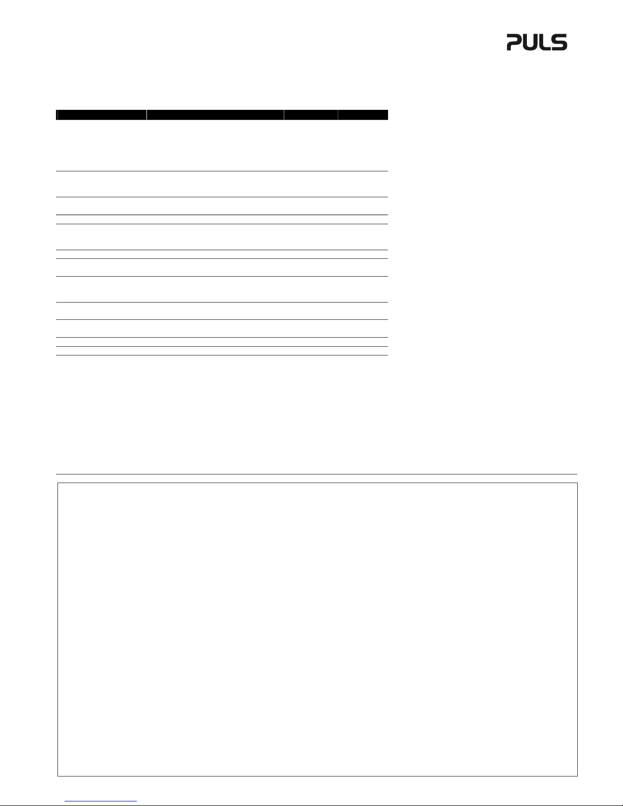
Technical Data 1) Technische Daten 1) UB10.241 UB10.245
Output Voltage Output 1 Ausgangsspannung Ausgang 1 nom. 22.25V 2) 22.25V
2)
Output Current Output 1 Ausgangsstrom Ausgang 1 nom. 15A 3) 15A
3)
nom. 10/ 15A 4) 10/ 15A
4)
Output Voltage Output 2 Ausgangsspannung Ausgang 2 nom. N/A 5) 12.0V
Output Current Output 2 Ausgangsstrom Ausgang 2 N/A 5) 5A
Output Power (total) Ausgangsleistung (gesamt) 240/ 360W 6) 240/ 360W
6)
Input Voltage Eingangsspannung DC 24V DC 24V
Input Voltage Range Eingangsspannungsbereich 22.5 – 30Vdc 22.5 – 30Vdc
Transfer Threshold Buffer Mode Umschaltschwelle Pufferbetrieb 22.25V 22.25V
Allowed Batteries Erlaubte Batterien 12V, VRLA 12V, VRLA
Allowed Battery Capacity Erlaubte Batteriekapazität 3.9Ah – 27Ah 3.9Ah – 27Ah
Power Losses Verlustleistung typ. 2.9/ 5.5W 7) 3.4/ 6W
7)
Operational Temperature Betriebstemperatur -25 - +70°C -25 - +70°C
Output Derating Leistungsrücknahme 6W/°C (60 - 70°C) 6W/°C (50 - 70°C)
Storage Temp. Range Lagertemperaturbereich -40 - +85°C -40 - +85°C
Humidity Feuchte IEC60068-2-30 5 - 95% r.H. 8) 5 - 95% r.H. 8)
Vibration Schwingen IEC 60068-2-6 2g 2g
Shock Schocken
IEC60068-2-27 30g 6ms, 20g 11ms 30g 6ms, 20g 11ms
Degree of Pollution Verschmutzungsgrad EN 50078 2 2
Degree of Protection Schutzart EN 60529 IP20 IP20
Over-temp. Protection Übertemperaturschutz Yes / Ja 9) Yes / Ja 9)
Parallel Use Parallelschaltbar No / Nein No / Nein
Serial Use Serienschaltbar No / Nein No / Nein
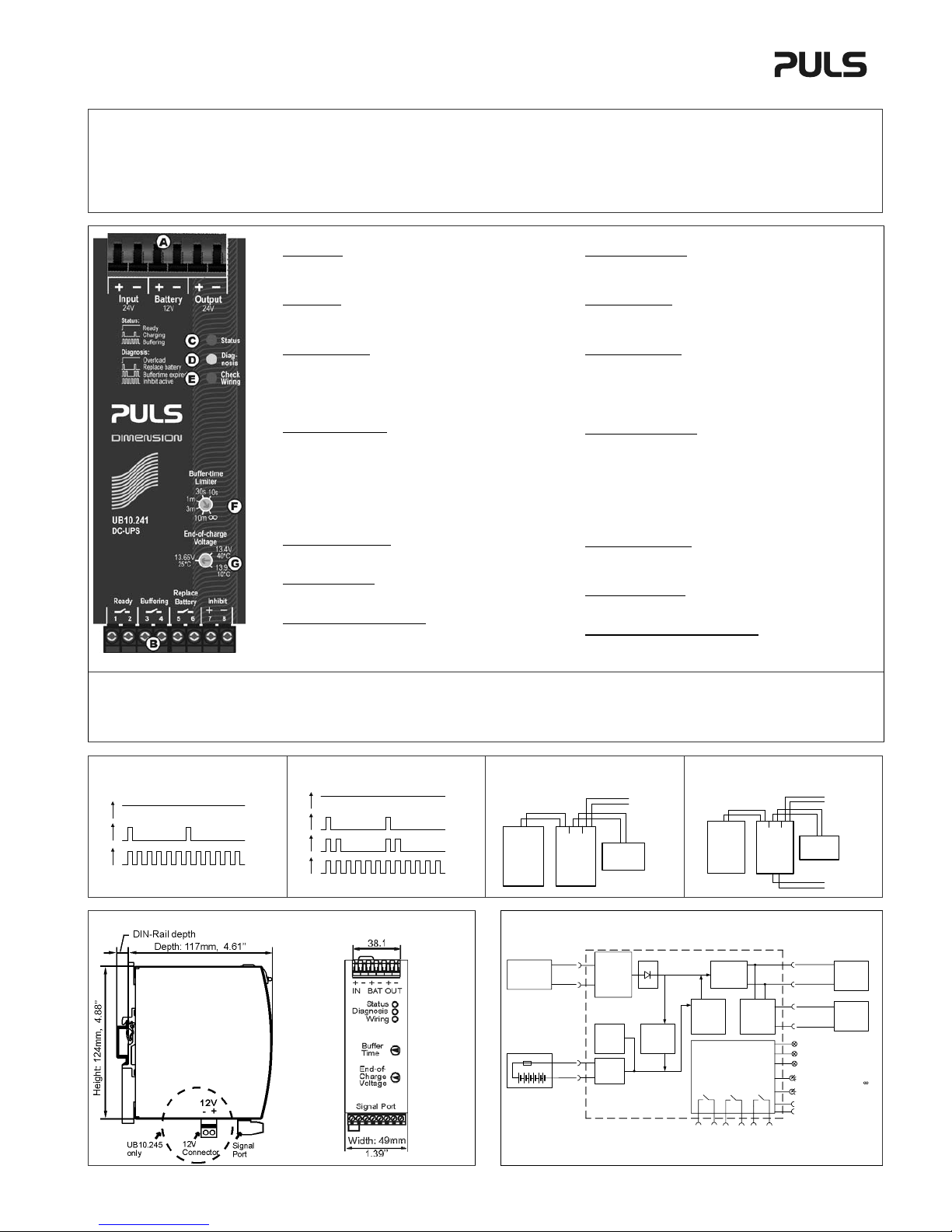
Dimensions)(wxhxd) Abmessungen (BxHxT) nom. 49x124x117mm 10) 49x124x117mm 10)
Weight Gewicht max. 530g / 1.17lb 650g / 1.43lb
Approvals Zulassungen 11) 11)
Limited Warranty (Year) Gewährleistung (Jahre) 3 3
1) All parameters are specified at 24Vdc input voltage, nominal output current, 25°C ambient and after a 5
minutes run-in time unless otherwise noted.
2) The output voltage is regulated to 22.25Vdc in a buffer event. In all other cases, the output voltage is
approx. 0.3V lower than the input voltage assuming that the input voltage is sufficient and no overload is
present.
3) When no buffer event is present.
4) During a buffer event 15A is available for the first 5 seconds. After this time, the output current is limited to
10A. UB10.245: 12V output not loaded.
5) Not applicable.
6) The allowed total output power is 360W when no buffer event is present as well as for the first 5 seconds
during a buffer event. After this, the allowed total output power is 240W. UB10.245: 12V output not loaded.
7) At no load / 10A load, no buffer event is present. UB10.245: 12V output not loaded.
8) Do not energize while condensation is present.
9) Output shuts down with automatic restart.
10) Depth without DIN-rail.
11) See datasheet or markings on the unit.
1) Alle Werte gelten bei 24Vdc Eingangsspannung, Nennausgangsstrom, 25°C Umgebung und nach
einer Aufwärmzeit von 5 Minuten, wenn nichts anderes angegeben ist.
2) Während eines Pufferfalls ist die Ausgangsspannung auf 22.25V geregelt. In allen anderen Fällen ist
die Ausgangsspannung etwa 0,3V kleiner als die Eingangsspannung vorausgesetzt, dass die
Eingangsspannung im spez. Bereich ist und kein Überlastfall vorliegt.
3) Wenn kein Pufferfall vorliegt.
4) Während eines Pufferfalls stehen für die ersten 5 Sekunden 15A zur Verfügung. Danach ist der
Ausgangsstrom auf 10A begrenzt. UB10.245: Gilt bei 0A Last am 12V Ausgang.
5) Nicht anwendbar.
6) Die erlaubte Ausgangsleistung ist 360W wenn kein Pufferfall besteht oder während der ersten 5
Sekunden eines Pufferfalls. Danach ist die erlaubte Ausgangsleistung 240W. UB10.245: Gilt bei 0A
Last am 12V Ausgang.
7) Bei Leerlauf / 10A Last und wenn kein Pufferfall besteht. UB10.245: 0A Last am 12V Ausgang.
8) Nicht betreiben, solange das Gerät Kondensation aufweist.
9) Ausgang schaltet ab und macht regelmäßig automatische Startversuche.
10) Tiefe ohne DIN-Schiene.
11) Siehe Datenblatt oder Prüfzeichen auf dem Gerät.
Installation Procedure
1. Use DIN-rails according to EN 60715 or EN 50022 with a height of 7.5 or 15mm. The unit is
convection cooled. Do not obstruct air flow! Ventilation grid must be kept free of any obstructions.
2. Connect the power supply to the input terminals of the DC-UPS.
3. Connect the battery to the battery terminals of the DC-UPS. It is recommended to install the
battery outside the cabinet or in a place where the battery will not be heated up by adjacent
equipment. Use a 30A battery fuse typ ATO® 257 030 (Littelfuse) or similar in the battery path.
The battery fuse protects the wires between the battery and the DC-UPS. It also allows the
disconnection of the battery from the DC-UPS which is recommended when working on the
battery or DC-UPS. Disconnect battery fuse before connecting the battery.
4. Please note:
Wires that are too small or too long between the DC-UPS and the battery can shorten the buffer
time or can result in a malfunction of the DC-UPS. Do not use wires smaller than 2.5mm2(or
12AWG) and not longer than 2x1.5m (cord length 1.5m). Avoid voltage drops on this connection.
5. Connect the buffered load to the output terminals of the DC-UPS. The output is decoupled from
the input allowing load circuits to be easily split into buffered and non buffered sections. Non-
critical loads can be connected directly to the power supply and will not be buffered. The energy in
the battery will be used in the circuits which require buffering.
6. Set the end-of-charge voltage potentiometer and the buffer time limiter to an appropriate value.
7. Install the fuse when the wiring is finished. Red LED on the DC-UPS should turn off.
Terminals and Wiring
The units are equipped with spring-clamp terminals for the power port and with a plug connector for
the signal port. Use appropriate copper cables that are designed for an operating temperatures of
60°C (for ambient up to 45°C) and 75°C (for ambient up to 60°C), minimum. Follow national
installation codes and regulations! Ensure that all strands of a stranded wire enter the terminal
connection! Ferrules are allowed, but not required.
Power terminals: (except 12V output)
Solid wire / Stranded wire / American wire gauge: 0.5-6mm2 / 0.5-4mm2 / 20-10 AWG
Wire stripping length: 10mm / 0.4inch
Pull-out force (UL 486E): 10AWG: 80N, 12AWG: 60N
12V output terminals: (For UB10.245 only)
Solid wire / Stranded wire / American wire gauge: 0.1-2.5mm2 / 0.1-2.5mm2 / 28-12 AWG
Wire stripping length: 8mm / 0.33inch
Pull-out force (UL 486E): 10AWG: 80N, 12AWG: 60N
Signal terminals:
Solid wire / Stranded wire / American wire gauge: 0.2-1.5mm2 / 0.2-1.5mm2 / 22-14 AWG
Wire stripping length: 6mm / 0.25inch
Recommended tightening torque: 0.4Nm / 3.5lb.inch
Installationsanleitung:
1.Geeignet zur Montage an DIN-Schienen entsprechend EN 60715 oder EN 50022 mit einer
Höhe von 7,5 oder 15mm. Das Gerät ist für Konvektionskühlung ausgelegt. Es ist für eine
ungehinderte Luftzirkulation zu sorgen.
2.Schließen Sie die Stromversorgung and die “Input” Klemmen der DC-USV an.
3.Schließen Sie die Batterie an die “Battery” Klemmen der DC-USV an. Es wird empfohlen, die
Batterie außerhalb des Schaltschranks oder so zu platzieren, dass diese nicht von
benachbarten Geräten aufgeheizt wird. Verwenden Sie eine 30A Sicherung z.B. Typ ATO®
257 030 (Littelfuse) o.ä. in dem Batterie-Pfad. Die Sicherung schützt die Kabelverbindung
zwischen Batterie und DC-USV. Außerdem kann diese zur Trennung verwendet werden.
Ziehen Sie die Sicherung heraus, bevor Sie die Batterie anschließen.
4.Bitte beachten Sie: Zu dünne oder zu lange Kabel zwischen DC-USV und Batterie können die
Pufferzeit verkürzen oder zum Fehlverhalten der DC-USV führen. Benutzen Sie keine
Anschlussdrähte kleiner als 2,5mm2und nicht länger als 2x1,5m (Kabellänge 1,5m).
5.Schließen Sie die zu puffernde Last an die „Output“ Klemmen an. Der Ausgang ist vom
Eingang entkoppelt. So kann man Lasten in gepufferte und ungepufferte Zweige aufteilen.
Unkritische Lasten können ungepuffert direkt an die Stromversorgung angeschlossen
werden. So wird die Energie der Batterie nur für zu puffernde Lasten verwendet.
6.Stellen Sie am "End-of-Charge-Voltage" Einsteller (Ladeschlussspannung) und "Buffer-Time-
Limiter" Einsteller (Pufferzeit-Begrenzer) den entsprechenden Wert ein.
7.Schließen Sie die Sicherung an, wenn alle Arbeiten an der Batterie oder DC-USV beendet
sind. Nach dem Einschalten muss die rote LED erlöschen.
Anschlussklemmen und Verdrahtung
Die Geräte sind mit Schnellanschluss-Federkraftklemmen ausgestattet. Verwenden Sie
geeignete Kupferkabel, die mindestens für 60°C (bei einer Umgebungstemperatur bis zu 45°C)
und 75°C (bei einer Umgebungstemperatur bis zu 60°C) zugelassen sind. Beachten Sie
nationale Bestimmungen und Installationsvorschriften! Stellen Sie sicher, dass keine einzelnen
Drähte von Litzen abstehen. Aderendhülsen sind erlaubt, aber nicht erforderlich.
Leistungsanschlussklemmen: (außer 12V Ausgang)
Starrdraht / Litze / Amerikanischer Querschnitt: 0,5-6mm2 / 0,5-4mm2 / 20-10 AWG
Abisolierlänge: 10mm / 0,4inch
Abziehkraft (UL 486E): 10AWG: 80N, 12AWG: 60N
Klemmen für 12V Ausgang: (Nur bei UB10.245)
Starrdraht / Litze / Amerikanischer Querschnitt: 0,1-2,5mm2 / 0,1-2,5mm2 / 28-12 AWG
Abisolierlänge: 8mm / 0,33inch
Abziehkraft (UL 486E): 10AWG: 80N, 12AWG: 60N
Signalklemmen:
Starrdraht / Litze / Amerikanischer Querschnitt: 0,2-1,5mm2 / 0,2-1,5mm2 / 22-14 AWG
Abisolierlänge: 6mm / 0,25inch
Empfohlenes Anzugsdrehmoment: 0,4Nm / 3.5lb.inch

DC-UPS Instruction Manual for the DIMENSION UB10-Series
Bedienungsanleitung für die DC-USV der DIMENSION UB10-Serie
EMC Electromagnetic Compatibility
These devices are suitable for applications in industrial environment as well as in residential,
commercial and light industry environment. These devices comply with FCC Part 15 rules.
Operation is subjected to following two conditions: (1) this device may not cause harmful
interference, and (2) this device must accept any interference received, including interference that
may cause undesired operation. CE mark is in conformance with EMC directive 89/336/EC,
93/68/EC and 2004/108/EC and the low-voltage directive (LVD) 73/23/EC, 93/68/EC, 2006/95/EC.
EMC Immunity: EN 61000-6-1, EN 61000-6-2
EMC Emission: EN 61000-6-3, EN 61000-6-4, FCC Part 15 Class B
EMV Elektromagnetische Verträglichkeit
Diese Geräte erfüllen die Anforderungen für Anwendungen sowohl in industrieller Umgebung
als auch für den Wohn-, Geschäfts- und Gewerbebereich.
Die Geräte erfüllen auch die Anforderungen der FCC Teil 15.
Das CE Zeichen ist angebracht und erklärt die Erfüllung der EMV Richtlinien 89/336/EG,
93/68/EG, 2004/108/EG und der Niederspannungsrichtlinien 73/23/EG, 93/68/EG, 2006/95/EG.
EMV Störfestigkeit: EN 61000-6-1, EN 61000-6-2
EMV Störaussendung: EN 61000-6-3, EN 61000-6-4, FCC Part 15 Klasse B
User Interface
A Power Port
Quick-connect spring-clamp terminals, for input voltage, output
voltage and battery. The 12V output of the UB10.245 is on the
bottom side of the unit.
B Signal Port
Plug connector, inserted from the bottom. Connections for the
Ready, Buffering, Replace Battery relay contacts and for the Inhibit
input.
C Green Status LED (see Fig. 1 for LED pattern)
Ready: Battery is charged, no wiring failure is recognized, input
voltage is sufficient and inhibit signal is not active.
Charging: Battery is charging and the battery capacity is below
85%.
Buffering: Unit is in buffer mode.
D Yellow Diagnosis LED (see Fig. 2 for LED pattern)
Overload: Output has switched off due to long overload in buffer
mode or due to high temperature.
Replace battery: Indicates a battery which failed the battery quality
test (SoH test). Battery should be replaced soon.
Buffer-time expired: Output has switched off due to setting of
Buffer-timer Limiter. This signal will be displayed for 15 minutes.
Inhibit active: Indicates that buffering is disabled due to an active
inhibit signal.
E Red Check Wiring LED
This LED indicates a failure in the wiring, battery, battery fuse or
installation (e.g. too low input voltage).
F Buffer-time Limiter
Limits the maximum buffer time during a buffer event to save the
battery energy, for a faster recharge and to expand the battery life.
G End-of-charge-voltage Selector
Set the end-of-charge-voltage according to the expected
temperature in which the battery is located. The dial on the front of
the unit allows a continuously adjustment between +10 and +40°C.
If in doubt about the expected temperature, set the unit to 35°C.
Benutzer Schnittstelle
A Leistungsanschlüsse
Federkraftklemmen für die Eingangs- und Ausgangsspannung sowie die
Batterie. Der 12V Ausgang des UB10.245 befindet sich an der
Unterseite des Gerätes.
B Signalanschlüsse
Steckverbinder von unten einsteckbar. Anschlüsse für die Ready,
Buffering, Replace Battery Relaiskontakte und für den Inhibit Eingang.
C Grüne „Status“ LED (Blinkmuster ist in Bild 1 erklärt)
Ready: Die DC-USV ist pufferbereit. Batterie ist geladen, kein Inhibit
Signal, kein Verdrahtungsfehler, Eingangsspannung ist ausreichend.
Charging: Die Batterie wird geladen und hat einen Ladezustand von
weniger als 85%.
Buffering: Die DC-USV ist im Pufferbetrieb.
D Gelbe „Diagnosis“ LED (Blinkmuster ist in Bild 2 erklärt)
Overload: Meldet einen abgeschalteten Ausgang, aufgrund von
Überlast während des Pufferbetriebes oder Übertemperatur.
Replace battery: Meldet, wenn die Batterie den Qualitätstest nicht
besteht. Batterie sollte baldmöglichst ersetzt werden.
Buffer-time expired: Meldet einen abgeschalteten Ausgang,
aufgrund von abgelaufener Pufferzeit (Buffer-Time-Limiter). Die
Meldung wird gespeichert und 15 Minuten lang angezeigt.
Inhibit active: Ein aktives Inhibit Signal verhindert eine Pufferung.
Rote „Check Wiring“ LED
Meldet eine notwendige Überprüfung der Verdrahtung zwischen DC-
USV und Batterie sowie eine notwendige Überprüfung der Batterie
selbst. Meldet auch, wenn die Eingangsspannung zu klein ist.
F “Buffer-time Limiter”
Mit diesem Einstellregler lässt sich die Pufferzeit begrenzen um die
Batterie zu schonen, und eine schnellere Nachladung zu erreichen.
G “End-of-charge-voltage” Einstellregler
Stellen Sie hier die zu erwartende Batterietemperatur ein. Es ist eine
stufenlose Einstellung zwischen +10 und +40°C möglich. Im Zweifelsfall
stellen Sie den Regler auf 35°C.
Ready (1-2)
Buffering (2-3)
Replace Battery (5-6)
Inhibit (7-8)
Contact is closed when battery is charged and unit is ready to buffer.
Contact is closed when unit is buffering.
Contact is closed when a replacement of the battery is necessary.
Buffering is disabled when an voltage > 8V is applied to the pins.
Relay contact rating: max. 60Vdc 0.3A, 30Vdc 1A, 30Vac 0.5A
resistive load; min. 1mA at 5Vdc; 500Vac insulated to the power port.
Kontakt ist geschlossen wenn die DC-USV geladen und pufferbereit ist.
Kontakt ist geschlossen wenn das Gerät im Pufferbetrieb ist.
Kontakt ist geschlossen wenn ein Austauschen der Batterie erforderlich ist.
Wenn eine Spannung > 8V anliegt ist eine Pufferung nicht möglich.
Belastbarkeit der Relaiskontakte: max. 60Vdc 0.3A, 30Vdc 1A, 30Vac
0.5A Widerstandslast; min. 1mA bei 5Vdc; isoliert mit 500Vac.
Fig. 1 / Bild 1 Fig. 2 / Bild 2 Fig. 3 / Bild 3 Fig. 4 / Bild 4
Ready
Charging
Buffering
ON
OFF
ON
OFF
ON
OFF
Overload
Replace
Battery
Buffer time
expired
Inhibit
active
ON
OFF
ON
OFF
ON
OFF
ON
OFF
Wiring diagram / Anschlussdiagram UB10.241
24V
Power
supply
+
-
NLPE
24V
buffered
branch
DC-UPS
UB10.241
24V
IN
24V
OUT
12V
BAT
+
-
+
-
+
-
12V
Battery
+
-
+
-
Wiring diagram / Anschlussdiagram UB10.245
24V
Power
supply
+
-
NLPE
24V
buffered
branch
DC-UPS
UB10.245
24V
IN
24V
OUT
12V
BAT
+
-
+
-
+
-
12V
Battery
+
-
+
-
12V
12V
buffered
branch
+
-
+
-
Dimensions / Abmessungen Functional Diagram / Funktionsschaltbild
DC-UPS Control Unit
Battery
Charger
Battery
Tester
Cut-off
Relay
Battery
+
-
12V Battery
24V
Power
Supply
Input
-
+
-
+
Reverse
Polarity
Protection
Input Fuse
&*Electronic
Current
Limiter
Buffered
Load
+
-
24V Output
Step-up
Converter
Step-down
Converter
(UB10.245
only)
+
-
(5) (6)
Ready
Contact
(1) (2)
Buffering
Contact
(3) (4)
Controller
Diagnosis LED (yellow)
Check Wiring LED (red)
Status LED (green)
Buffer-time Limiter
10s, 30s, 1m, 3m, 10m,
End-of-charge Voltage
Inhibit -
Inhibit +
Replace
Battery
Contact
(7)
(8)
12V Output
(UB10.245 only)
Buffered
Load
*Return current protection: This feature utilizes a MOSFET instead of a diode to minimize power losses.
PU-357.011.00-10A
Other manuals for dimension UB10.241
1
This manual suits for next models
1
Table of contents
Other Puls UPS manuals