CHY 804R User manual

12
OPERATING INSTRUCTIONS
MODEL 804R
DUAL INPUT RTD THERMOMETER
INTRODUCTION
This instrument is a 4½ digit, compact-sized portable
digital thermometer designed to use external 100ΩPlati-
num RTD as temperature sensor. Temperature indication
follows Reference Temperature/Resistance Tables (Pt385
for European Curve, Alpha=.00385. Pt3926 for American
Curve, Alpha=.003926.)
Features of the instrument include:
yDual Input Function
yPt3926/Pt385 RTD Standard
yAccording to temperature standard ITS-90
yResistance Measurement
yOne-second measurement cycle
yReal Time indicate
yMAX/MIN with elapsed time
yAVG, REL, HOLD function
yWarning beeper with Hi/Lo setting
yTime setting
yREL Setting
y°C/°F user-selective
yTemperature resolution: 0.1°C or 0.1°F
yReading Resistance resolution: 0.1Ω
yReading Resistance resolution by PC: 0.01Ω
yMultiple signal: 3000 samples with start-time data
ySingle signal: 32 samples with real-time data
ySupport user-linear table setting by PC
yUSB Mini-B interface standard
yOptional 12V DC power
SAFETY INFORMATION
It is recommended that you read the safety and opera-
tion instructions before using the thermometer.
WARNING
To avoid electrical shock, do not use this instrument
when working voltages at the measurement surface
over 24V AC or DC.
WARNING
To avoid damage or burns, do not make temperature
measurement in microwave ovens.
SPECIFICATIONS
ELECTRICAL
Temperature Scale: Celsius or Fahrenheit user-selectable.
Measurement Range:
Pt385(100Ω) -200°C to 800°C, (-328°F to 1472°F)
Pt3926(100Ω) -200°C to 630°C, (-328°F to 1166°F)
Temperature Resolution: 0.1°C or 0.1°F
Temperature Accuracy:
±(0.05% rdg + 0.2°C) on °C scale
±(0.05% rdg + 0.4°F) on °F scale
Accuracy is specified for operating temperatures over the
range of 18°C to 28°C (64°F to 82°F), for 1 year, not in-
cluding RTD probe error.
Temperature Coefficient: 0.1 times the applicable accu-
racy specification per °C from 0°C to 18°C and 28°C
to 50°C (32°F to 64°F and 82°F to 122°F).
Resistance Range: 0 to 400Ω
Resistance Resolution:
0.1Ω(Meter Reading)
0.01Ω(PC Reading)
Resistance Accuracy:
±(0.05% rdg + 2dgts) Meter Reading
±(0.05% rdg + 4dgts) PC Reading
Input Protection: 24V dc or 24V ac rms maximum input
voltage on any combination of input pins.
Input Connector: Accepts for RTD 4 wires subminiature
4-Prong type connectors.
Maximum Differential Common Mode Voltage:
1volt. (Maximum Voltage between T1 and T2 during
measurement)
Back Side:
1. USB Port
2. DC power JACK(12V)
ENVIRONMENTAL
Ambient Operating Ranges:
0°C to 50°C (32°F to 122°F) <70% R.H.
Storage Temperature:
-20°C to 60°C (-4°F to 140°F) <80% R.H.
GENERAL
Display: 4½ digit liquid crystal display (LCD) with
maximum reading of 19999.
Overload: “----.-”or “OL” is display.
Battery: 1.5V x 4 PCS (SIZE AAA) UM-4 R03.
Battery Life: 120 hours typical with carbon zinc battery.
Reading Rate: 1 times per second.
Auto Power Off: 30 minutes, press power key to resume
operation.
Dimensions: 160mm(H) x 83mm(W) x 38mm(D).
Weight: Approx. 260g including batteries.
OPERATING INSTRUCTIONS
1. “ ”Power Switch
The “ ” key turns the thermometer on or off. In the
SET mode can not be powered off. Exit SET mode to
power off.
APO function mode
Press “ ” power key for more than 6 seconds to
disable the auto-power function. The display will show
“APO OFF”.
2. “°C/°F/Ω” Selecting Button
To change the scales of °C/°F/Ω, press the “°C/°F”
key to cycle through °C, °F and Ω. When the ther-
mometer is turned on, it is set to the temperature scale
that was in use when the thermometer was last turned
off.
3. “ ” Display Back-Light
Press the “ ” key to turn on or turn off the
Back-Light.
4. “T1 T2/T1-T2” Main display Input Selection
The input selection indicates which input is selected
for main display; T1 probe, T2 probe or the difference
between the two probes (T1-T2). When the thermometer
is turned on, it is set to T1, when main display input se-
lected T1, then T1 input can select alternate of probe by
pressing “Pt385/Pt3926” key switch.
5. “TYPE” (Pt385/Pt3926)Main display Input
RTD Probe Select
The “TYPE” key switches the T1 input to select the
Pt385 or Pt3926 or User Liner RTD probe as input
when main display input selected T1. It is invalid for the
selection of these parameters when the main display se-
lects T1-T2. When the thermometer is turned on, it is set
to the probe selected that was in use when the ther-
mometer was last turned off. Switch flow: Pt385,
Pt3926, User Linear.
(*)User Linear please refer section 16.
6. “MAX/MIN”
With Time record Mode (only Main display)
Press “MAX/MIN” key to enter the MIN MAX Re-
cording mode, (displays the Maximum reading with
time, Minimum reading with time and Average reading
stored in recording mode). In the this mode the auto-
matic power-off feature is disabled and “ ” key,
“°C/°F” key, “REL” key, “SET” key, “Hi/Lo LIMITS”
key and main display “T1 T2 T1- T2” key, “TYPE” key
are disabled. The beeper emits a tone when a new
minimum or maximum value is recorded.
Push “MAX/MIN” key to cycle through the MAX,
MIN and AVG readings.
If an overload is recorded, the averaging function is
stopped. In this mode, press “HOLD” key to stop the
recording of readings, all values are frozen, press again
to restart recording. To prevent accidental loss of MAX,
MIN, and AVG data, this mode can only be cancelled
by pressing and holding the “MAX/MIN” key for 2
seconds. All recorded readings are erased.
7. “REL” Relative Mode(only Main display)
Press the “REL” key to enter the relative mode, zero
the display, and store the displayed Reading as a refer-
ence value. REL is shown on the display. Press “REL”
key again to exit the relative mode. The relative refer-
ence value can also be entered by the user. (See “SET
mode” later in this manual). When the desired relative
value has been entered, press “REL” key to enter the
relative mode and than press “SET” key use the entered
relative value as a reference value. Press “REL” key
again to exit the relative mode. In the relative mode, the
value (can not >±1999.9 counts) shown on the LCD is
always the difference between the stored reference and
the present reading.
8. “HOLD” Mode(only Main display)
Press the “HOLD” key to enter the Data Hold mode,
the “HOLD” annunciator is displayed. When HOLD
mode is selected, the thermometer held the present
readings and stops all further measurements. Press the
“HOLD” key again to cancel HOLD mode causing
thermometer to resume taking measurements. In the
MIN/MAX recording mode, press “HOLD” key to stop
the recording. Press “HOLD” key again to resume re-
cording. (Previously recorded read are not erased).
9. “SET” Mode (Relative value set, Date set,
Time set and Hi/Lo Limits value set)
9.1 REL SET
Press “SET” key to enter REL setting mode (Press
“ENTER” key can escape relative values set mode), and
the “= = = =.=” is displayed in main display. Relative
value is entered via overlay numbers, then press overlay
“ENTER” key, stored the relative value, enter Data/
Time set mode.
9.2 Date/Time SET
In the Data setting mode, (press “ENTER” key can
escape Date set mode), “= = = = = =” is displayed in
third display. Date(years, month, day) value is entered
via overlay numbers, then press overlay “ENTER” key.
When the user inputs(years, month and day) in order,
and then press “ENTER” key to enter into the time set-
ting.
In the time setting mode, (Press “ENTER” key can
escape Time set mode) “= = = = = =” is displayed in
third display. Time (hours, minutes, seconds) value is
entered via overlay numbers, then press overlay
“ENTER” key. When the user inputs(hours, minutes
and seconds), and then press “ENTER” key to enter
“Hi/Lo LIMITS” setting mode.
9.3 Hi Limit SET
In the Hi Limit value setting mode, (Press “ENTER”
key can escape Hi Limit value set mode), “= = = =.=” is
displayed in main display, Hi Limit value is entered via
overlay numbers, then press overlay “ENTER” key,
stored the Hi Limit value, enter Lo Limit value set
mode.
9.4 Lo Limit SET
In the Lo Limits setting mode, (Press “ENTER” key
can escape Lo Limit value set mode). “= = = =.=” is
displayed in main display, Lo Limit value is entered via
overlay numbers, then press overlay “ENTER” key,
stored the Lo Limit value and exit SET mode.
10.
“T1 T2 T1-T2” Second display Input Selection
The input selection indicates which input is selected
for second display; T1 probe, T2 probe or the difference
between the two probes (T1-T2), when the thermometer
is turned on, it is set to T2 input can select alternate of
probe by second display Pt385/Pt3926 key switch.
11. “TYPE” (Pt385/Pt3926) Second display Input
RTD Probe Select
The “TYPE” key switches the T2 input to select the
Pt385 or Pt3926 or User Liner RTD probe as input
when second display input selected T2. It is invalid for
the selection of parameters when the second display se-
lects T1-T2. When the thermometer is turned on, it is set
to the probe selected that was in use when the ther-
mometer was last turned off. Switch flow: Pt385,
Pt3926, User Linear.
(*)User Linear please refer section 16.
12. “Hi/Lo LIMITS” Mode(only Main display)
Press “Hi/Lo LIMITS” key to enter the Hi/Lo Limits
comparative mode. When the input temperature value
exceed the Hi or Lo Limits value, the beeper emits a
continuous or pulse tone. Press “Hi/Lo LIMITS” key
again to exit the Hi/Lo Limits mode.
13. Data logger Operation
zSingle log
Press the “HOLD” key to enter the Data Hold mode,
the “HOLD” annunciator is displayed. Then press
“SET” key, save hold data to single data memory.
And LCD show “S-xx”, and the “xx” is the location
on the single data memory. Then resume Hold func-
tion.
zMultiple log
Press the “HOLD” key to enter the Data Hold mode,
the “HOLD” annunciator is displayed. Than press
“MAX/MIN” key, starting the multiple log. LCD
show “L-xx”, and the “xx” is the location on the mul-
tiple data memory. When “RECORD” flashes the
meter start saving data into memory. Both “RECORD
& HOLD flashing that means entering key delay.
Wait the HOLD con stop flashing, which means en-
tering data collecting. Key delay setting please refer
to software operation for more detail.
Press “MAX/MIN” key again to exit the Multiple log
mode. LCD show “SPxx”, that “xx” is the location on
the multiple data memory. If battery is low, that will
stop automatically.
zData download
Data download by PC. Please refer to the PC soft-
ware document.
zErase logger data
Pressing “MAX/MIN” key and “ ” power key for-
more than 6 seconds into the memory erasing mode
and LCD shows “CLr”. Pressing “Hi/Lo” key for
more than 2 seconds then erase memory. When mem-
ory is clean, the display will show “End”. And the
meter will shut down about one second, which the
memory is complete.
14. User-Linear table
Please refer to the PC software document.
15. User calibration
In the shut-down mode, press “ ” key and “ ” key
for more than 6 seconds then the third display(tower
right display), will show “CAL 2”. Which means en-
tering the user calibration mode. Under this mode in-
serts the calibrated 0Ωresistor T1 socket, and then the
calibrated 383Ωinto Y2 socket. And press “Hi/Lo”
Limits key to complete the calibration, the meter emits
a beep then LCD shows “End”. The meter will shut
down after one second. To cancel the user calibration
is to press the second display “T1/T2/T1-T2” key, and
the LCD will show “Def” after one second the meter
will shut down to restore the factory default.
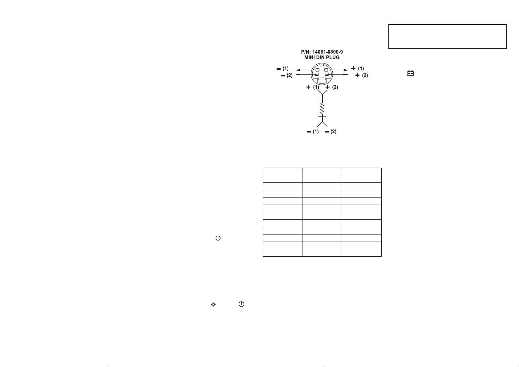
Connection
RTD Probe Connection
Temperature & Resistance Table
TEMPERATURE VS RESISTANCE
TABLE(ITS90)
°C Pt385 Pt3926
-200°C 18.521Ω16.996Ω
-100°C 60.256Ω59.479Ω
0°C 100.000Ω100.000Ω
100°C 138.505Ω139.272Ω
200°C 175.856Ω177.362Ω
300°C 212.052Ω214.275Ω
400°C 247.092Ω250.018Ω
500°C 280.977Ω284.591Ω
600°C 313.708Ω317.994Ω
700°C 345.280Ω-
800°C 375.700Ω-
OPERATOR MAINTENANCE
WARNING
To avoid possible electrical shock, disconnect the
thermocouple connectors from the thermometer before
removing the cover.
Battery Replacement
1. Power is supplied by 4pcs 1.5V (SIZE AAA) UM-4
R03.
2. The “ ” appears on the LCD display when replace-
ment is needed. To replace battery remove screw from
back of meter and lift off the battery cover.
3. Remove the battery from battery contacts and replace.
4. When not use for long time remove battery.
5. Don’t keep in place with high Temp, or high humidity.
Cleaning
Periodically wipe the case with a damp cloth and deter-
gent, do not use abrasives or solvents.
*Software operation manual is on the software disk.
V1. 110507
Other CHY Thermometer manuals


