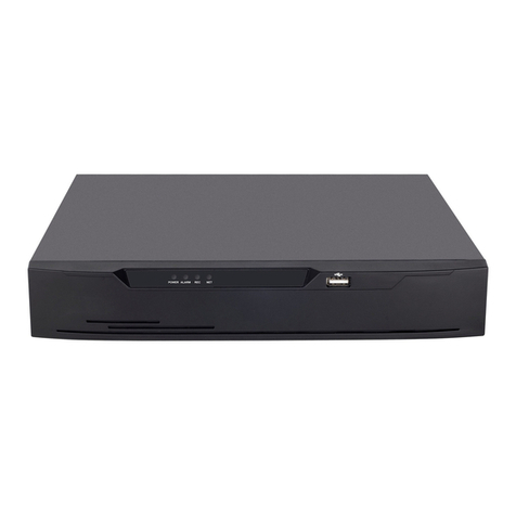
TeleEye RV432 User manual

Copyright ○
c 2005-2006
All Rights Reserved
Mobile Digital Video Recorder with
Advertisement/ Multimedia
Playback
Instruction Manual

©2005-2007
TABLE OF CONTENTS
Section Page
I. Product Components and Features 3
II. Installation Guidelines 4
II.1 Installation Environment Requirements 4
II-2 Mounting / Enclosing the MDR 4
II-3 Installation Parts and Materials Required 5
II-4 MDR Product Views 5
II-5 MDR Dimension 6
II-6 MDR Package Contents 7
II-7 MDR Installation Location Guidelines 8
II-8 MDR Installation Instructions 9
II-9 MDR Installation Layout 10
II-10 MDR Bridal Connection Guideline 11
II-11 MDR Visual Orientation 14
II-12 Handheld IR Remote Controller Functions 16
III. System Start-up/ Shut down 19
IV. MDR system layout 21
IV-1 Multimedia Management 21
A) Advertisement 21
B) Music 22
C)Movie 23
IV-2 Playback Management 24
A) Search – Normal Recorded Playback 24
B) Search – Event Recorded Playback 26
V. System Setup Management 27
V-1 System Setup 27
A) Date/Time 28
B) General 29
C) Video Type 31
D) Audible Alarm 32
E) Priority Record 33
F) HDD O/W 34
G) HDD Format 35
H) Network 37
I) Security 38
J) Default Setup 40
K) USB Operation 42
L) Driver Info 43
V-2 Camera Setup 44
V-3 Recording Schedule 46
V-4 Event Setup 47
V-4-1 Sensor Menu 47
V-4-2 Motion Detect Menu 49
V-5 PTZ Setup 50
V-6 System Information: 51
VI. System Firmware Upgrade Procedure 53
VII. Compact Flash Card management 54
VIII. Hard Disk File Structure 57
IX. GPS Operation (Optional) 58
Appendix A 59

MDR Manual
2

MDR Manual
3
I. Product Components and Features
System Recording Module and Mounting Assembly
zUltra compact case, extremely low weight, high temperature resistance, and vibration resistant
zLow-Voltage, low-current architecture suitable for mobile mounting or fixed locations
zQuick-Release removable Recording Module with tamperproof lock and secure controls
zFlexible Mounting Assembly for permanent connection to vehicle or permanent installation
zIndividual wire connections for audio, video, power, inputs/outputs, and accessory assemblies
z12v, 3Amp regulated power for use with cameras, inputs/outputs, and accessory assemblies
zFull support for NTSC or PAL video inputs and outputs, audio channels, VGA display
zCommunications supported through TCP/IP network interface and USB connection to PCs
zHand-held, IR controller with On-Screen Display (OSD) for all operations of the MDR
z2.5-in. mobile anti-vibration and shock resistance HDD
Video and Audio DVR Features and Capabilities
z4 channels for video input, full-motion (30FPS/camera) continuous or priority video recording and live
display
z4 channels for high-fidelity, digitally recorded, synchronized audio matched to 4 video channels
zContinuous recording while in the playback mode
zUser friendly criteria to playback the events associated video only
zAutomatic timer to resume the live display if the unit is idle for user defined timings
zMPEG-4 video compression for high quality, low storage recording and playback
zUser-selectable settings for quality and audio record enable/disable for each video channel
z12v power supply for multiple devices such as cameras, sensors, relays and any other accessories
zSelectable frame rate with event-triggered burst recording speeds up to 30FPS/camera
zMultiple alarm inputs with selectable pre-alarm and post-alarm record timings
zTV output channel for live video and recorded video viewing
Streaming Video Output for Multimedia Contents
zDVD-quality steaming audio/video with NTSC or PAL composite or VGA output
zFlash card, USB media update
zIndependent operation of DVR and streaming advertising simultaneously
Remote Connection Capabilities
zHandheld Infra-Red controller with OSD for quick access to recorded video and settings menus
zUSB connection for file transfer, PC-based file transfer and settings management
zPC-Based Client software for live viewing, playback video, playback events associated video, and
downloading capabilities
zSupport CMS (Central Management System), Auto download program, Analysis program;
Accessory Modules for MDR
zVideo Interface Module including GPS location and speed
zVehicle Motion Manager includes 3-axis inertia sensor to determine video-matched motion events
zVideo event search allows intelligent searching of recorded video based on event logs

MDR Manual
4
II. Installation Guidelines
II-1 Installation Environment Requirements
In order to ensure the reliable operation of your Mobile Digital Recorder (MDR) within the terms of the product
warranty, follow these instructions for installing your MDR
a) Follow all electrical codes, adhere to all requirements for your vehicle and for other connected
equipment while installing and operating the MDR.
b) Use only a regulated 12-volt DC or 24-volt DC (2 ~ 3 Amps) certified power supply for installation in
vehicles. The MDR can handle power ranges from 7v ~ 28v DC. Follow the installation and
operating instructions provided to ensure a steady and reliable source of installation. Handle all
electric equipment and connections properly to avoid injuries.
c) Even though the recording unit may not be turned on, live power exists in the mounting assembly
and precautions should be taken to avoid shock. Disconnect the power supply from its source
before connecting or disconnecting the MDR mounting assembly from the power supply.
d) Do not attach any device specified or approved by Vendor.
e) Do not attach powered input leads that exceed 12-volt DC at 1.5 Amps OR 5-volt DC at 1.5 Amps
supply on any one connection.
f) Attach the MDR ground cable to the vehicle correctly to complete the power circuit.
g) Install the MDR in a dry location shielded from direct contact with excessive humidity and moisture,
rain or other sources of liquid spills. Do not install on a recessed surface where liquids may
accumulate or under surfaces where liquids may drip.
h) Do not handle the MDR with wet hands, while standing in water, or while in contact with other
sources of water or moisture that could create a shock hazard.
i) Install the MDR out of direct sunlight and away from direct sources of heat.
j) Do not mount the unit to a surface subject to excessive vibration.
II-2 Mounting / Enclosing the MDR
a) MDR may be operated in a totally sealed enclosure with no cooling airflow, ensure that the operating
temperature of the MDR does not exceed 140°F (60°C) or that the standing temperature does not
exceed 175°F (80°C). The minimum operating temperature for the MDR is -20°F (-28°C). If the
minimum temperature is expected to exceed connect an auxiliary heat source.
b) MDR assembly may be mounted on a flat surface, provide at least 6 inches (15cm) clearance for
cooling airflow around the remaining sides to provide adequate heat dissipation.
c) To clean any surface of the MDR, use only cleaners approved for electronic equipment or
components. Avoid chemical or household cleaners.
d) Disconnect MDR mounting assembly from the power supply when not in use for extended period of
time.

MDR Manual
5
II-3 Installation Parts and Materials Required
The following common tools and parts are required to install MDR
•Drill and bids for mounting in vehicle
•Screws/bolts and vibration dampening washers as appropriate for mounting
•Wire cutters and wire connectors
•Voltmeter
II-4 MDR Product Views
Front View Rear View (without connections)
Assembled Chassis Details
Height 4.9 cm (1.93 inch)
Width 17.9 cm (7.04 inch)
Depth 24.5 cm (9.64 inch)
Weight 3.25 lb
Recording Module (Removable Component)
Height 4.6 cm (1.81 inch)
Width 17.9 cm (7.04 inch)
Depth 17.6 cm (6.92 inch)
Module Removal Clearance 16.5 cm (6.49 inch)
Installation Clearance (except base ) 10 cm (6 in)
Mounting Assembly / Recording Module Removed

MDR Manual
6
II-5 MDR Dimension
17.9 cm
1
7.5
c
m
24.5 cm
4.9 cm
4
.6
c
m

MDR Manual
7
II-6 MDR Package Contents
The following materials are shipped with the MDR. Ensure that you unpack all contents of your
shipment and confirm receipt of the following items for each unit:
a) MDR Recording Module and Mounting Assembly
b) DB37 bridal (AV input/ Sensor connectors/ Inertia sensor connector)
c) DB25 bridal (AV output / VGA connector/ RS232/ RS485/ Control panel connector)
d) USB Cable
e) 20 PCs screws
f) GPS Antenna (with GPS equipped models only)
g) Warranty card
h) User Manual CD
i) Hand held IR remote controller (batteries not included)
a b c
d e f
g h i

MDR Manual
8
II-7 MDR Installation Location Guidelines
Following are the general guidelines for the installation purposes. Choose a location in the vehicle
that meets the following items:
Power: It is recommended that the MDR be connected to the vehicle ignition. Battery power is
used only when the vehicle is running. MDR could drain any vehicle battery over time if
the ignition is not turned off.
Connection: Connect only to appropriate power supply and ensure proper grounding of the circuit.
Moisture: Protect unit and connections from environmental sources of moisture and liquid spills.
Temp: Do not install where unit temperature will exceed F140°F (60°C), fall below -20°F (-28°C)
or store the unit where temperatures rise above 175°F (80°C). Avoid direct exposure to
sunlight.
Ventilation: Provide sufficient ventilation with a minimum of 6 inches cooling clearance to ensure
proper operating temperature for the unit.
Vibration: If necessary, provide additional shock mounting to prevent damage and wear by
excessive vibration.
Clearance: Front clearance of 16.5 cm or 6.49 inch is required to slide the recording module from
the mounting assembly.
Wiring: Install where mounting assembly wires have sufficient clearance and will not be crimped
or subject to wire insulation damages due to vibration.
Access: Secure the MDR so that passengers or drivers cannot tamper or damage the unit,
cameras, wires or other accessories. Do not mount where access to any other vehicle
component will be restricted.
Injury: Install the unit, cameras, accessories and wires so that no injuries can be caused
through impact with equipment during vehicle operation. Ensure that all transportation
regulations are followed to avoid passenger injury should they come in contact with the
installed equipment.

MDR Manual
9
II-8 MDR Installation Instructions
Follow these guidelines when installing the MDR:
•Remove all components provided in the package.
•Disconnect any power supply or device.
•Slide the recording module from the mounting assembly.
•Locate a proper spot to install the mounting assembly and provide any additional shock
absorption if necessary.
•Locate a reliable electrical ground point in the vehicle.
•Make all connections to the rear of the mounting assembly.
•Place the mounting assembly and permanently attach to the supporting structure using
screws.
•Slide the recording module on to the mounting assembly to ensure proper clearance.
•Connect the provided bridals to MDR.
•Connect power source and turn the vehicle ignition (make sure this connect with “Signal”) to
test the unit.
•Observe completion of the unit power-up procedures as described in section labeled as
“System Startup and Shutdown”.
•Apply any information labeling required by local statute for video surveillance.

MDR Manual
10
II-9 MDR Installation Layout
Note: This is a sample I/O Schematic. Sensors are not reserved for any device.
Sensors can be connected to any external device in any order. The label in the
setup differentiates the sensors connected to the I/O.

MDR Manual
11
II-10 MDR Bridal Connection Guideline
DC IN:
The bridal description for the power cable supplied with MDR is as follows:
DC OUT:
The bridal description for the power cable supplied with MDR is as follows:
Input Bridal DB37 (Video/Audio IN/ Sensor Input/ Inertia connection):
The bridal description for the Input bridal supplied with your MDR is as follows:
Color coded wire Description
INPUT (Red) Positive wire. Should be
connected to the positive terminal
of the battery
INPUT GROUND
(Black) Negative (ground) wire. Should be
connected to the negative terminal
of the battery
SIGNAL (Yellow) Connect with car ignition to let the
system start up (need provide +ve
DC power as signal ON/OFF)
Color coded wire Description
OUTPUT (Red) Positive Power wire, provide the
power to camera or other device.
(the voltage directly draw from
“POWER INPUT” bypass the MDR)
OUTPUT
GROUND (Black) Negative (ground) wire, provide
the power to external device or
equipment
Power IN
Power OUT

MDR Manual
12
Output Bridal DB25 (Video/Audio Out/ RS232/ RS485/ Control Panel):
The bridal description for the Output bridal supplied with your MDR is as follows:
LRemark: PIN Definition (DB37 and DB25) shown in Appendix A
Label Description
V 1 Video input for camera number 1
V 2 Video input for camera number 2
V 3 Video input for camera number 3
V 4 Video input for camera number 4
A 1 Audio input for camera number 1
A 2 Audio input for camera number 2
A 3 Audio input for camera number 3
A 4 Audio input for camera number 4
Color coded wire Description
Sen 0 (Red) Sensor 1 (0~12V)
Sen 1 (Red) Sensor 2 (0~12V)
Sen 2 (Red) Sensor 3 (0~12V)
Sen 3 (Red) Sensor 4 (0~12V)
Sen 4 (Red) Sensor 5 (0~12V)
Sen 5 (Red) Sensor 6 (0~12V)
Sen 6 (Red) Sensor 7 (0~12V)
Sen 7 (Red) Sensor 8 (0~12V)
Sen V (Yellow) Speed capture
A/D (Blue) Enable the Analog to Digital input for
Sensor 1 to Sensor 2
TO SENSOR Connect with Inertia Sensor
Label Description
V1 Composite output for controlling
MDR. IR handheld is fully
functional when connected to V1
output
V2 Composite output for live camera
view only. IR handheld is not
operational when connected to V2
output
AL Left Audio output
AR Right Audio output
VGA VGA output for controlling MDR. IR
handheld is fully functional when
connected to VGA output
RS232A
RS232B RS232 allow connect external
device (GPS/Meter/Lasar Gun)
Connecting with MDR
RS232D Serial Port for system diagnostic
RS232C RS485 A/ B (for PTZ connecting
with MDR)
TO DB15 Connect with Control Panel
external device

MDR Manual
13
GPS Antenna (Optional):
zMDR is capable of embedding GPS coordinates and speed
on the video.
zMDR uses a passive GPS technology which does not
require any service subscription from local service provider.
zPassive GPS receives the signal from satellite as latitude,
longitude and speed after negotiating with the satellite. It
takes approximately 3-5 minutes after boot up to start the
negotiation process with the satellite to receive the signals.
When the negotiation is completed a graphical icon at the
live display shows the availability of GPS.
zIf the negotiation fails an X is marked on the graphical icon
showing the failure of satellite communication.
zThis GPS option can provided the time synch features for
MDR device;
zConnect the GPS antenna provided with your set (if ordered
GPS equipped DVR) and hang it such that the front of the
antenna is upwards facing the sky.
Network Connection (RJ45):
zUsing the network cable to link with MDR to network system, allow browse into the system using
client software or remote access to MDR;

MDR Manual
14
II-11 MDR Visual Orientation
Front Panel Layout (Recording Module):
1. LED Indicator and Status Display:
[10M/100M] Network connection speed: LED ON for 100M bps, LED off for 10M bps.
[LINK/ACT] Network connection activity light: LED blinking indicates data transfer.
[HDD] Hard disk drive activity: LED ON indicates system is reading/writing to hard disk.
[REC] Video recording status: LED ON indicates recording is on for at least one channel.
[ALM] Alarm status: LED ON indicates unit is currently responding to an alarm condition. Alarm
can be caused by an external sensor trigger, hard disk failure and video loss
[POWER] Input power status: LED ON confirms that unit is powered.
[ERR] Error status with USB connection: LED blinks while USB connection problem occur.
[ACC] USB connection status: LED blinking indicates data transfer using USB port.
[CF] CF card status: LED ON indicates that CF card is inserted and the data is accessible.
LNotice: when the [ALM] on, caused by video loss or trigger “High Speed Limit” sensor, require login as
administrator to disable the alarm LED and buzzer from control panel;
2. IR Receiver Lens:
Please ensure that the MDR is installed where the handheld IR controller can be pointed
directly to the IR receiver lens. Point your handheld controller at the spot on the recording
module allowing the unit in responding to commands from the controller.
3. CF Card Slot:
To upgrade the MDR software and transfer files without the use of a PC, use an industry
standard Compact Flash card and the handheld controller. For uploading instructions refer to
section labeled as “System Upgrade Firmware Procedure”
4. USB Port:
The USB 2.0 transfer port allow to transfer data file from mobile unit to PC, also MDR can act
as host device to copy advertising clips from USB thumb drive.
(
1
)
LED Indicato
r
(
2
)
IR Receive
r
(
3
)
CF Card Slot
(
4
)
USB Port

MDR Manual
15
Back Panel Layout (Docking Module):
Rear Connections (Mounting Assembly):
All connections to the MDR are attached to the rear of the Mounting Assembly using pre-assembled bundles
of wire specifically labeled for each purpose.
Terminal Block A: Power INPUT and OUTPUT Connections
Terminal Block B: DB37 (Audio/ Video Signal Inputs/ Sensors connections/ Inertia connection)
Terminal Block C: DB25 (Audio/ Video Signal outputs/ VGA/ RS232/ RS485/ Control Panel connection)
Terminal Block D: GPS Antenna Connection
Terminal Block E: Network connection port (RJ-45)
Disconnecting a bridal does not affect the operation of remainder of the MDR functions
BA CED

MDR Manual
16
II-12 Handheld IR Remote Controller Functions
Each MDR includes a handheld Infra-Red (IR) controller that allows the user to transmit commands to
recording module and display on screen control menu either on a composite monitor (V1 output) or a
regular monitor (VGA).
Numeric
Input Keys
Use the numbers to input
values in the system setup
screen or switch through
the channels in live and
playback. Plus and Minus
is used to increase setup
values one by one.
Navagation
Arrows
Use the ARROW keys to
move between selections,
input fields and icons.
Press ENTER to select
and EXIT to return. Next
and previous is also used
to increase or decrease
volume when at live or
serach screens.

MDR Manual
17
Handheld IR Controller Key Functions:
1. Numeric Keypad:
[0-9] keys: During setup, number keys are used to input values.
For viewing channels 1, 2, 3 and 4 use 1, 2, 3 and 4 on numeric keypad respectively.
[+], [-] keys: During setup, plus and minus are used to select next or previous values.
During real time view of individual camera, after you pressed key use plus and minus
to make the color adjustments. Pressing will navigate through the color adjustment
options. Please be advised that the unit needs to stop recording before any color adjustments
are made.
2. Setup Menu Navigation:
▲, ▼: Up, Down directional keys: Moves selection up and down in setup menu.
►, ◄: Left, Right directional keys: Moves cursor left or right in setup menu.
[ENTER] key: During setup, select and save entry
During live view, displays time on screen
During Playback, displays the text or hide the text associated with video on
the screen
3. Other Key Functions:
LOGIN/ LOCK If the security is enabled in the setup, use LOGIN / LOCK or SETUP
key to enter the user setup
POWER The Power button can reset the DVR in to sleep mode (unit will stop
recording while in the sleep mode)
VGA Switch the output mode to VGA
VIDEO Switch back from VGA to composite output (V1)
RECORD / STOP Used to start or stop the recording manually. The recording schedule
has to be disabled for the manual recording to work
Swapping between multi-channel and single channel monitor
while in surveillance screen only. Press this button to change the
number of display channels. By pressing the key, display channel
change in the sequence of four→one→two→three→four
Brightness, contrast, color adjustment per channel. While in
surveillance screen, go to full screen on individual camera by
pressing the corresponding number on numeric keypad of IR. Press
to activate the function. Use [+] [-] button to change the
values. User can adjust the values for each channel individually.
Please be advised that the unit needs to stop recording before any
color adjustments are made
SETUP System setting screen (may require login)
EXIT Returns to the previous menu. Pressing exit key takes one step back
in the until the live monitor screen is displayed

MDR Manual
18
3. Other Key Functions (Continue):
PAUSE/STEP
▐►
Freezes playback to a single frame and can advance one frame at a
time. To advance the frame press Pause / Step to move frame by
frame. Press EXIT to return to normal playback speed
PLAY ►Starts/Resumes playback from any other mode (FF, RR, Frame by
Frame etc)
SLOW Reduces playback speed to 1/2, 1/4, 1/8 modes. Press PLAY to
return to normal playback speed
GOTO ÎQuick search mode within the file playing back. Select the desired
file and start to play. Press GOTO button and input the desired time.
Select START to jump to the specific time
NEXT Increase volume while playback (if audio is recorded) or multimedia
playback
PREV Decrease volume while playback (if audio is recorded) or multimedia
playback
REW Rewinds the video while playback. X2 and X 4 modes available
FWD Fast forward the video while playback. X2 and X4 modes available
CF While CF card inserted, this button can activate the CF function
F 3 Move between one clip to another while playing back recordings
[F1], [F2], [F4] Reserved for future use
4. Pan/Tilt/Zoom Function Controls:
While connect with PTZ camera and using the RS485a/b, following command can control with
PTZ camera with following function:
[ZOOM IN +], [ZOOM OUT -] ZOOM IN/OUT
[IRIS +], [IRIS-] IRIS control
[FOCUS +], [FOCUS -] FOCUS IN/OUT
PTZ Start to active the PTZ function
AUTO Auto run with the PTZ pattern
PRESET Preset default position
RECALL Recall the set program
BRUSH Brush the glass screen

MDR Manual
19
III. System Start-up/ Shut down
1. System Start Up
After connecting the MDR to a vehicle power supply turn on the vehicle ignition and the unit will
automatically start recording. Power is normally supplied to the MDR as long as the vehicle ignition is ON.
Start-up process takes approximately 10 seconds and completes as follows:
•A short series of start-up diagnostic test to ensure system stability
•Recording from connected cameras begins immediately (factory default)
•“Display only view” of the cameras is immediately available to be viewed through Video Output 2 in
quad view. No handheld IR controls are accepted by MDR when video output is connected to V 2
•“Administrative view” of the system is available to be viewed through Video Output 1. All the
handheld IR controls are accepted by MDR when video is connected to V 1 or VGA
Note: MDR factory settings are programmed to display administrative view on VGA monitor. If MDR is
connected on the Video output 1, press the VIDEO button on the IR to switch to composite monitor output.
Please see a list of factory default settings under “System Default Settings” explanation page.
2. System Login for Setup Functions
The unit have password authorization enabled in order to enter setup. The IR will not response to any
commands until SETUP or LOGIN key is pressed for validating the user authority of MDR. To enter a
password:
•Press the LOGIN/LOCK or SETUP key on the handheld controller
•When a menu appears on the display, enter the Unit ID and stored password (Default unit is 000 and
password is 88888888)
•Press ENTER on the handheld controller. If the password is accepted, the setup menu will appear.
Two levels of password are available in the setup.
•USER PASSWORD CORRECT indicates permission is limited to playback, advertisement,
movie and music. Default USER password is 22222222.
•ADMIN PASSWORD CORRECT indicates full access to MDR. Default ADMIN password is
88888888.
(000)
Table of contents
Other TeleEye DVR manuals

TeleEye
TeleEye GX684 User manual

TeleEye
TeleEye JN6500-S User manual

TeleEye
TeleEye RA Series Manual

TeleEye
TeleEye RX364 User manual
TeleEye
TeleEye JN6204 User manual
TeleEye
TeleEye JN204X DVR User manual

TeleEye
TeleEye RX504 User manual
TeleEye
TeleEye RM134 User manual

TeleEye
TeleEye RM134 User manual
TeleEye
TeleEye RA204 User manual

TeleEye
TeleEye JN308 User manual
TeleEye
TeleEye RX538 User manual
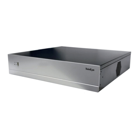
TeleEye
TeleEye GN6516 User manual
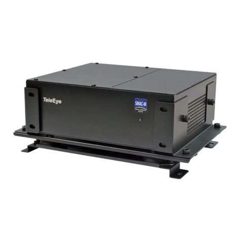
TeleEye
TeleEye RX538 User manual

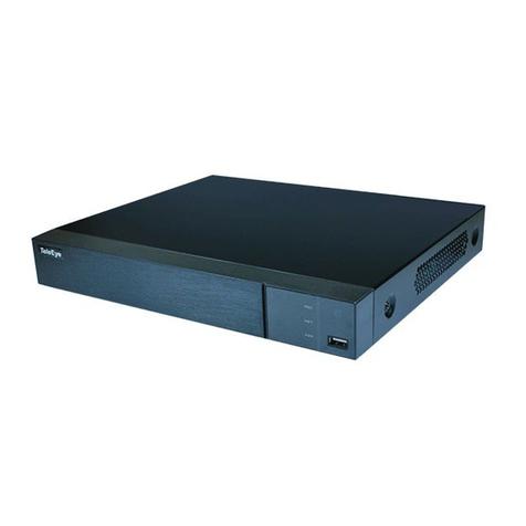
TeleEye
TeleEye GN8808 User manual
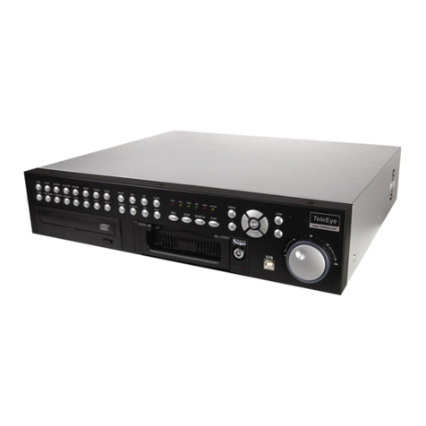
TeleEye
TeleEye JN6400 User manual

TeleEye
TeleEye GN8816 User manual
TeleEye
TeleEye RN284 User manual
TeleEye
TeleEye RN684 User manual
TeleEye
TeleEye RX324_V3 User manual

