CiA ECO300 User manual

ECO300
230Vac geared-motor for 2,5m hinged gate
ECO400
230Vac geared-motor for 3,5m hinged gate
Installation Manual
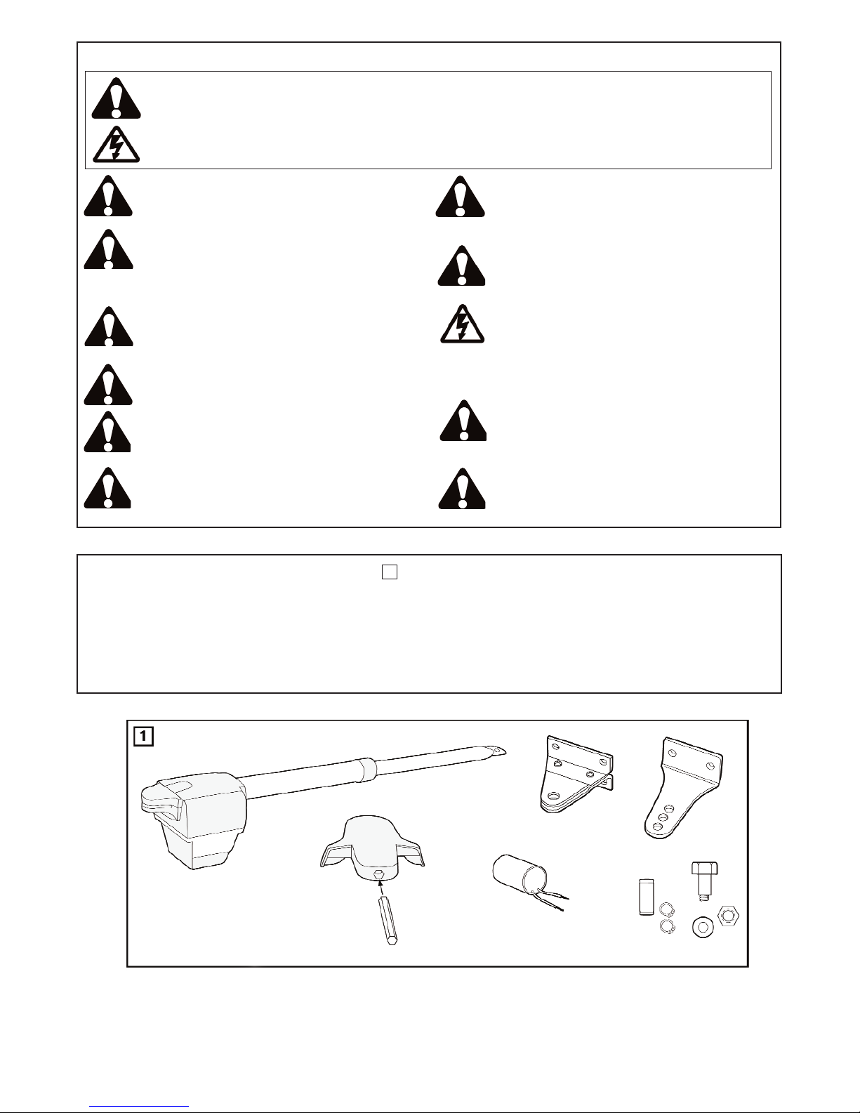
CONTENT OF THE CARTON ECO300KS/ECO400KS
(1) Motor
(2) Gate fixing bracket
(3) Key
(4) Fixing Systems
(5) Condenser
(6) Manual
(7) Clevis pin and rings
1
PLEASE STA RT B Y READING THESE IMPORTANT SAFETY RULES SAVE THESE INSTRUCTIONS
Installation and wiring must be in compliance with
your local building and electrical installation codes.
Power cables must only be connected to a properly
earthed supply.
Any entrapment possibility by the moving wing
between wing & walls must be secured with safety
edges or IR-sensors.
Disconnect electric power to the system before
making repairs or removing covers.
A disconnecting device must be provided in the
permanently-wired installation to guarantee all-pole
disconnection by means of a switch (at least 3mm
contact gap) or by a separate fuse.
When using tools and small parts to install or carry
out repair work on a gate exercise caution and do
not wear rings, watches or loose clothing.
Make sure that people who install, maintain or
operate the gate drive follow these instructions. Keep
these instructions in a safe place so that you can
refer to them quickly when you need to.
Please remove any locks fitted to the gate in order to
prevent damage to the gate.
It is important to make sure that the gate always
runs smoothly. Gates which stick or jam must be
repaired immediately. Employ a qualified technician
to repair the gate, never attempt to repair it yourself.
This safety alert symbol means "Caution" - failure to comply with such an instruction involves risk of personal injury or
damage to property. Please read these warnings carefully.
This gate drive mechanism is designed and tested to offer appropriately safe service provided it is installed and operated
in strict accordance with the following safety rules.
Incorrect installation and/or failure to comply with the following instructions may result in serious personal injury or
property damage.
Keep additional accessories away from children. Do
not allow children to play with pushbuttons or remote
controls. A gate can cause serious injuries as it
closes.
After the installation a final test of the full function of
the system and the full function of the safety
devices must be done.
The full protection against potential squeeze or
entrapment must work direct when the drive arms are
installed.
This drive cannot be used with a gate incorporating
a wicket door unless the drive cannot be operated
with the wicket door open.
1
BEFORE YOU BEGIN
The drive mechanism needs room to the side permitting correct installation of drive arms. Please make sure that this is available. Gates affected
by high wind loads must also be protected by an (electric) lock.
There are many factors to consider when choosing the right drive mechanism. Assuming that a gate functions properly, "startup" is the most difficult
phase, once the gate is in motion, significantly less force is usually required to move it.
• Gate size: Gate size is a very important factor. Wind can brake or distort the gate, thereby increasing the amount of force needed to move it
considerably.
• Gate weight: The weight of the gate in not as relevant as the size.
• Effect of temperature: Low outdoor temperatures can make initial startup more difficult (changes in the ground, etc.) or even prevent it. High
outdoor temperatures along with frequent use can trigger thermal protection prematurely (approx. 135 ºC).
• Operating frequency/operating time: Drive mechanisms are designed for a maximum operating time (running time) of approximately 30% (e.g.
30% during any one hour).
IMPORTANT: The drive mechanism is not designed to operate continuously at its maximum operating time (non-stop operation). Otherwise the
drive mechanism becomes too hot and switches off until it cools down to the switch-on temperature. The outdoor temperature and the gate are
important parameters that affect the actual operating time.
INSTALLATION CHECKLIST - PREPARATIONS
Check the carton contents and read the instructions carefully. Make sure your gate equipment operates perfectly. The gate must run evenly and
smoothly and must not stick at any point. Remember that the ground level may be several centimeters higher in winter. The gate must be stable
and as free of backlash in order to prevent any unwanted movement. The more smoothly the gate wing runs, the more sensitive the force
adjustment must be.
Write down any materials you still need and obtain them before starting to install. Heavy-duty plugs, bolts, gate stops, cables, distribution boxes,
tools, etc.
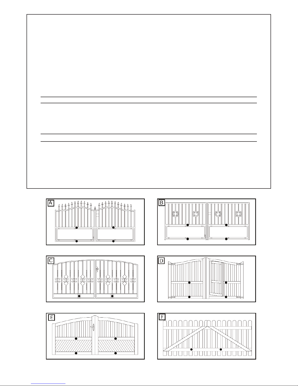
GATE TYPES
The gate type determines the location where the drive mechanism is installed. If the gate stop is on the ground, the drive mechanism must also
be installed at a height that is as low as possible so that it cannot twist the gate. Use only parts of the gate frame for fixing purposes.
For steel gates, the gate fitting must be attached to the main frame. If you are uncertain whether the available support is sufficiently stable,
reinforce it.
In the case of wooden gates, the gate fitting must be bolted through. It is advisable to fit a plate from the outside so that the fixing brackets cannot
become loose over time. Thin wooden gates must also be reinforced in order to withstand the stresses encountered.
2
D-4
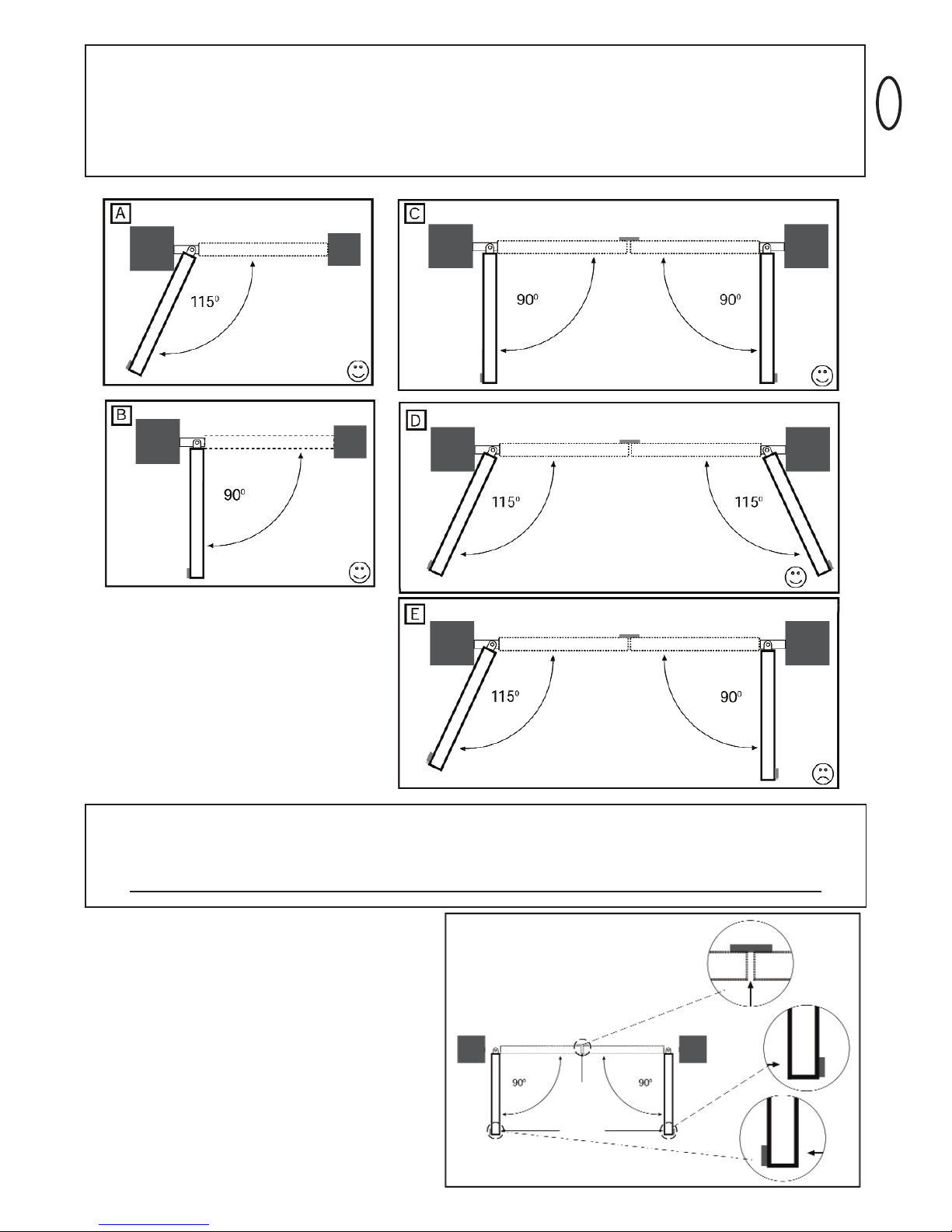
GATE CONFIGURATION
How far must the gate wing open?
90 degrees or up to 115 degrees. An opening angle in excess of 115 degrees is possible but is not recommended. Reason: the drive mechanism
always runs at the same speed. The further the gate has to be opened, the faster the wing must travel. Movement becomes more erratic and this
subjects the fittings and gate to extreme stresses. Different opening angles cause one motor to reach its destination first, but continues to run,
thereby forcing the gate up against the gate stop until the other motor eventually reaches its end position.
GATE STOPS
A SWING GATE NEEDS A FIXED GATE STOP IN BOTH THE OPEN AND CLOSE POSITIONS. Gate stops save wear and tear on the motor,
gate and fittings. Operating a gate without fixed limit stops results in poor performance. It is often dangerous, leads to premature wear and voids
Your warranty!

3
POST FIXING BRACKET
Choosing the correct location for the post fixing bracket has a decisive impact on the subsequent functioning of the system. It determines the
distance between the motor's centre of motion and the gate's centre of motion and hence the opening angle. These dimensions are referred to as
dimension A and dimension B. Do not underestimate the effect that these dimensions have on correct functioning and running. Try to achieve the
best possible dimension for your opening angle that is suitable for all circumstances. See Table for dimensions A/B.
If the post is not wide enough, an extension piece must be fitted to it. If the post is too thick, cut out part of it to make it thinner or offset the gate.
To obtain ideal dimensions, it may be necessary to shorten or lengthen the supplied hinge plate. In the case of gates that are to be custom made,
if the gate hinges are fitted on the posts appropriately, it is possible to influence dimensions A and B. Before the final mounting dimensions are
determined, you should always check whether or not there is any possibility that the corner of the drive mechanism will hit the post as the gate
swings.
INSTALLATION: The drive mechanism exerts considerable force against the post. Usually, acceptable mounting dimensions are obtained if the
supplied hinge plate is welded directly onto the post. In the case of thick stone or concrete posts, the hinge must be welded to a base plate and
attached so that the plugs cannot work loose during operation. Heavy-duty plugs where a threaded rod is bonded into the masonry stress-free are
more suitable for this purpose than steel or plastic straddling plugs. In the case of brickwork pillars, bolt a relatively large steel plate that covers
several bricks on to it and then weld the hinge plate to it. An angled plate attached over the corner of the post is also a good means of fixing the
operators.
This manual suits for next models
1
Table of contents
Popular Gate Opener manuals by other brands

Nortek Security & Control
Nortek Security & Control Mighty Mule HD272 installation manual

tousek
tousek TURN 10 Installation and operating instructions

SOMFY
SOMFY AXOVIA 220B RTS installation instructions

Nice HySecurity
Nice HySecurity CBOX1050 Installation and programming manual

CAME
CAME FROG-PM4 installation manual

Aprimatic
Aprimatic ONDA 500 installation instructions


