CIAT DESTRATIFIER TPL 4000 User manual

H4000 HELIOTHERME
DESTRATIFIER
TPL 4000
06 - 2019
EN7512234-03
Instruction manual

H4000 HELIOTHERME EN-2

ORIGINAL TEXT: FRENCH VERSION
1 - RECEIPT OF THE UNIT .......................................................................................................................................................... 4
2 - HANDLING .............................................................................................................................................................................. 4
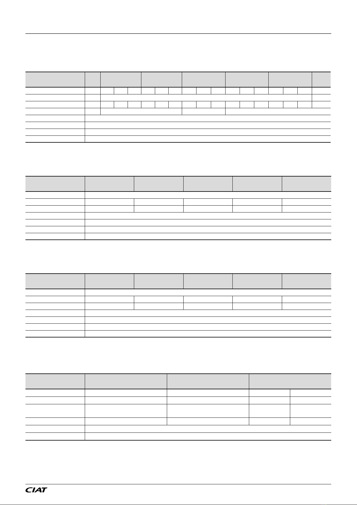
3 - TECHNICAL CHARACTERISTICS ......................................................................................................................................... 5
3.1 - ROTOREX fan motor assembly .......................................................................................................................................... 5
3.2 - CORROBLOC fan motor assembly..................................................................................................................................... 5
3.3 - HEE fan motor assembly (EC motor).................................................................................................................................. 6
4 - HEAT EXCHANGER................................................................................................................................................................ 7
4.1 - Low Pressure Water Coil..................................................................................................................................................... 7
4.2 - High Pressure Fluid Coil (superheated water, oil, etc.) ....................................................................................................... 7
4.3 - High Pressure Steam Coil (HPSC)...................................................................................................................................... 7
4.4 - Electric heater (EH)............................................................................................................................................................. 7
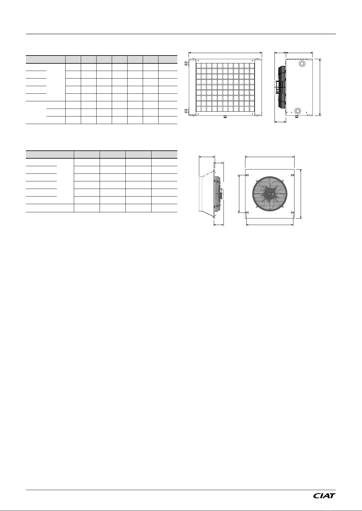
5 - DIMENSIONS........................................................................................................................................................................... 8
5.1 - H4000 Heliotherme ............................................................................................................................................................. 8
5.2 - TPL4000 Destratier ........................................................................................................................................................... 8
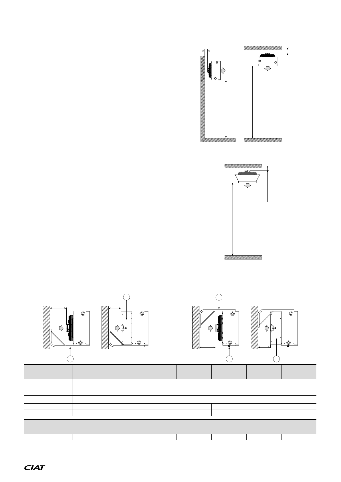
6 - SETUP ..................................................................................................................................................................................... 9
6.1 - H4000 Heliotherme ............................................................................................................................................................. 9
6.2 - TPL4000 Destratier ........................................................................................................................................................... 9
6.3 - Wall-mounted H4000 Heliotherme ...................................................................................................................................... 9
6.4 - Ceiling-mounted H4000 Heliotherme ................................................................................................................................ 10
7 - WATER CONNECTIONS ........................................................................................................................................................11
7.1 - Connection to be tightened (HELIOTHERME LP Water) ...................................................................................................11
7.2 - Connection to be welded (Heliotherme HP uid) ...............................................................................................................11
7.3 - Condensate drain connection (HELIOTHERME used for cooling or reversible purposes) ................................................11
8 - ELECTRICAL CONNECTIONS............................................................................................................................................. 12
9 - POWERING UP ..................................................................................................................................................................... 13
10 - MAINTENANCE................................................................................................................................................................... 13
11 - FREQUENTLY ASKED QUESTIONS.................................................................................................................................. 13
12 - TESTS AND WARRANTY ................................................................................................................................................... 14
13 - ASSEMBLY OPTIONS......................................................................................................................................................... 14
14 - CONTROL UNITS................................................................................................................................................................ 15
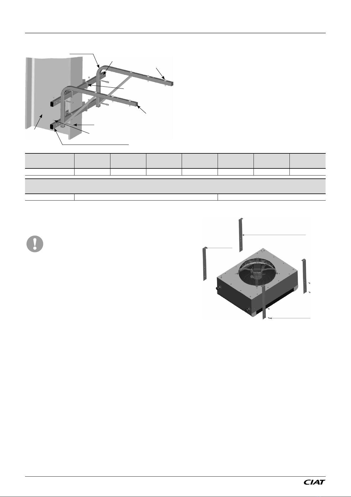
15 - WALL BRACKET................................................................................................................................................................. 17
16 - FILTER BOX ........................................................................................................................................................................ 18
17 - DIFFUSER ON DOOR ......................................................................................................................................................... 19
18 - DIFFUSER FOR LARGE SPACES...................................................................................................................................... 20
19 - FINAL SHUTDOWN............................................................................................................................................................. 21
CONTENTS
EN-3 H4000 HELIOTHERME

Thank you for purchasing a 4000 series HELIOTHERME or TPL. We hope that you will be completely satised with this CIAT air
heater or destratier unit.
To ensure correct operation, all connections (electrical, hydraulic, etc.) must be made in accordance with industry practice and the
regulations in force in the country of use.
Your unit must be maintained as recommended in this manual.
1 - RECEIPT OF THE UNIT
The unit is delivered in packages which are labelled for easy identication (type, model, etc.).
Each unit bears a name plate. The reference number shown on the name plate must be quoted in all correspondence.
It is the recipient's duty to inspect the contents of the packages upon receipt:
-In the event of missing items, the customer must provide the exact number of parcels delivered.
-If any damage is found upon delivery, describe the damage observed on the delivery receipt
in the presence of the delivery driver before the delivery note is signed.
IMPORTANT: In accordance with Article 133 of the French Code
of Commerce, these claims must be reported to the carrier by
registered letter within three business days of receipt. The terms
"conditional" and "pending unwrapping" shall have no value.
The client must unwrap the goods in the presence of the driver.
Claims must be made at the time of delivery and be described
in detail.
For an air heater operating with more than 10% fresh air, this is
not compliant with Regulation (EU) No. 1253/2014.
50° max
TPL
HELIO
2 - HANDLING
Handle the unit with care.
The unit can be installed with a forklift truck using the slings. These should be positioned on the 2 lifting rings as shown in the
diagram below.
H4000 HELIOTHERME EN-4

3 - TECHNICAL CHARACTERISTICS
3.1 - ROTOREX fan motor assembly
1 Ph/230 V AC motor
Use Model Motor Rotation
speed
Nom.
current
Abs.
pressure IP Thermal cut-
out Class Operating temp.
HEATING
H4350
SINGLE-
PHASE
230 V
50 Hz
1330 rpm 0.70 A 150W 44
NO
F
-40°C / +60°C
H4400 / TPL4400 1400 rpm 1.30 A 300W
54 YES
6.3 A - 165 °C
-40°C/+70°C
H4450 / TPL4450 1380 rpm 2.01 A 480W
H4500 / TPL4500 1403 rpm 2.78 A 630 W
H4630 / TPL4630 913 rpm 2.60 A 580 W
3 Ph/400 V AC motor
Use Model Motor Rotation speed Nom.
current Abs. pressure IP Thermal cut-out Class Operating temp.
HEATING
H4350
THREE-
PHASE
400V
50 Hz
HS - ∆ 1385 rpm 0.35 A 110W 44
NO
F
-40°C / +60°C
LS 1175 rpm 0.15 A 70W
H4400 /
TPL4400
HS - ∆ 1404 rpm 0.50 A 260 W
54 YES
6.3 A - 165 °C
-40°C/+70°C
LS 1176 rpm 0.30 A 170 W
H4450 /
TPL4450
HS - ∆ 1385 rpm 1.13 A 550 W
LS 1040 rpm 0.64 A 380 W
H4500 /
TPL4500
HS - ∆ 1391 rpm 1.51 A 770 W
LS 1176 rpm 0.90 A 520 W
H4630 /
TPL4630
HS - ∆ 870 rpm 1.30 A 590W
LS 750 rpm 0.63 A 250 W
H4630S
HS - ∆ 870 rpm 1.30 A 590W
LS 750 rpm 0.63 A 250 W
3.2 - CORROBLOC fan motor assembly
CORROBLOC 1 Ph/230 V AC motor
Use Model Motor Rotation speed Nom.
current Abs. pressure IP Thermal cut-out Class Operating temp.
HEATING
H4350
SINGLE-PHASE
230 V
50 Hz
1225 rpm 1.00 A 200W
65 YES
6.3 A - 165 °C
F -40°C/+70°C
H4400 1200 rpm 1.60 A 340W
H4450 1290 rpm 2.30 A 480W
H4500 1290 rpm 3.00 A 650W
H4630 800 rpm 2.60 A 510W
CORROBLOC 3 Ph/400 V AC motor
Use Model Motor Rotation speed Nom.
current Abs. pressure IP Thermal cut-out Class Operating temp.
HEATING
H4350
THREE-PHASE
400V
50 Hz
HS - ∆ 1260 rpm 0.5 A 200W
65 YES
6.3 A - 165 °C
F -40°C/+70°C
LS 950 rpm 0.2 A 120 W
H4400
HS - ∆ 1350 rpm 0.80 A 300W
LS 1000 rpm 0.4 A 200W
H4450
HS - ∆ 1230 rpm 1.0 A 500 W
LS 810 rpm 0.5 A 310 W
H4500
HS - ∆ 1350 rpm 1.6 A 660 W
LS 1060 rpm 0.9 A 450W
H4630
HS - ∆ 905 rpm 1.26 A 530 W
LS 650 rpm 0.6 A 300W
EN-5 H4000 HELIOTHERME

3.3 - HEE fan motor assembly (EC motor)
Single-phase motor
Use Model Motor ROTATION SPEED NOM.
I (A)
P. (W)
ABS IP Protection CLASS Operating
temp.
HEATING
H4300
1 PH/230 V
50/60 Hz
1500 rpm 0,80 85 54 TACH B -25 °C/+55 °C
H4350 1480 rpm 1,35 165 54 TACH B -25 °C/+50 °C
H4400 / TPL4400 1760 rpm 2,2 500 55
NC 250 VAC/2 A
F -25 °C/+60 °C
H4450 / TPL4450 1500 rpm 2,2 500 55
NC 250 VAC/2 A
F -25 °C/+60 °C
H4500 / TPL4500 1440 rpm 3,25 740 55
NC 250 VAC/2 A
F -40 °C/+60 °C
H4630 / TPL4630 1020 rpm 3,2 730 55
NC 250 VAC/2 A
F -40 °C/+60 °C
COOLING
H4300
1 PH/230 V
50/60 Hz
1500 rpm 0,80 85 54 TACH B -25 °C/+55 °C
H4350 1040 rpm 0,65 73 54 TACH B -25 °C/+60 °C
H4400 / TPL4400 1760 rpm 2,2 500 55
NC 250 VAC/2 A
F -25 °C/+60 °C
H4450 / TPL4450 1500 rpm 2,2 500 55
NC 250 VAC/2 A
F -25 °C/+60 °C
H4500 / TPL4500 970 rpm 1,1 250 55
NC 250 VAC/2 A
F -25 °C/+60 °C
H4630 / TPL4630 770 rpm 1,1 250 55
NC 250 VAC/2 A
F -25 °C/+60 °C
N.B.: Warning: if the HEE motor is being used without a control, please respect the rotation speeds (with control voltage) listed
below
Use Model Rotation speed Maximum control voltage (V)
HEATING
H4300 1500 rpm 10
H4350 1359 rpm 9
H4400 / TPL4400 1605 rpm 7,7
H4450 / TPL4450 1507 rpm 9,9
H4500 / TPL4500 1325 rpm 8,1
H4630 / TPL4630 1000 rpm 7,7
COOLING
H4300 1280 rpm 8,5
H4350 1095 rpm 9,5
H4400 / TPL4400 1111 rpm 5
H4450 / TPL4450 1018 rpm 5
H4500 / TPL4500 974 rpm 10
H4630 / TPL4630 772 rpm 10
3 - TECHNICAL CHARACTERISTICS
H4000 HELIOTHERME EN-6

4 - HEAT EXCHANGER
4.1 - Low Pressure Water Coil
Copper tube
Aluminium honeycomb fins
LP water coil H4300 H4350 H4400 H4450 H4500 H4630 H4630S
Number of heating rows 2 1 2 3 1 2 3 1 2 3 1 2 3 1 2 3 1
Number of cooling rows 2 3 -
Coil capacity (L) 0,8 0,68 1,18 1,66 0,96 1,59 2,28 1,38 2,27 3,22 2,18 3,38 4,55 2,97 4,7 6,4 2,97
Connection diameter ½ " ¾ " 1 " 1 " ¼
Connection type Threaded unions 243 GCU F/M
Operating pressure 13 bar
Max pressure 16 bar
Max T° 110°C
4.2 - High Pressure Fluid Coil (superheated water, oil, etc.)
316L stainless steel tube
Aluminium honeycomb fins
HP oil/water coil H4350 H4400 H4450 H4500 H4630
Number of heating rows 1
Coil capacity (L) 1,19 1,69 - 2,66 3,69
Connection diameter mm 33,7 42,4 - 42,4 42,4
Connection type Smooth 316L stainless steel (to be welded)
Maximum operating pressure
16 bar
Test pressure 24 bar
Max T° 200°C
4.3 - High Pressure Steam Coil (HPSC)
316L stainless steel tube
Aluminium honeycomb fins
HP steam coil H4350 H4400 H4450 H4500 H4630
Number of heating rows 1
Coil capacity (L) 0,97 1,22 - 1,95 2,86
Connection diameter mm 26,9 33,7 - 48,3 48,3
Connection type Smooth 316L stainless steel (to be welded)
Maximum operating pressure
16 bar
Test pressure 24 bar
Max T° 200°C
4.4 - Electric heater (EH)
Stainless steel single-tube heater
Aluminium honeycomb fins
Electric heater H4350 H4400 H4500
Electrical power kW 9,6 18,9 28,8 43,2
No. of stages 2 2 2 3
Heating element output
per unit kW 0,8 0,9 1,2 1,2
Power per stage kW 2,4 - 7,2 5,4 - 13,5 10,8 - 18 14,4 - 14,4 - 14,4
Connection type Manifold block
Max T° Double overheating thermostat with AUTO and MAN reset
EN-7 H4000 HELIOTHERME

5 - DIMENSIONS
5.1 - H4000 Heliotherme
Size H4300 H4350 H4400 H4450 H4500 H4630 H4630S
A
mm
395 460 555 618 714 874 872
B600 646 700 813 918 1050 1050
C286 286 286 286 336 336 295
D- 101 142 142 142 142 126
E* 126 126 143 143 188 200 -
Weight
(kg)
1 row - 21 30 40 50 62 60
2 rows 18 24 32 42 53 67 -
3 rows - 26 34 44 56 72 -
E* = HEE FMA
A
BDC
E*
5.2 - TPL4000 Destratier
Size TPL40 TPL45 TPL50 TPL63
A
mm
586 666 747 907
B183 212 225 273
C143 143 143 143
D370 470 570 705
E* 143 143 188 200
F552 632 712 872
Weight kg 17 22 25 33
E* = HEE FMA
A
A
F
D
B
E*
C
H4000 HELIOTHERME EN-8

6 - SETUP
6.1 - H4000 Heliotherme
To ensure correct air diusion and to comply with the EN 294
standard relating to safety zones, you are recommended to
position HELIOTHERME units at a height of:
-Between 2.5 and 4.5 metres when wall-mounted
-Between 4.5 and 10 metres when ceiling-mounted.
If the fan motor assembly is removed, also ensure that the rear
of the unit is a sufficient distance from the wall to allow access:
Min: 0.15 m
Min: 0.15 m
Min: 2.5 m
Max: 4.5 m
Min: 4.5 m
Max: 10 m
6.2 - TPL4000 Destratier
To ensure correct air diusion and to comply with the EN 294
standard relating to safety zones, you are recommended to
position DESTRATIFIERS at a height of:
-Between 5 and 15 metres.
The rear of the unit must be at least 145 mm from the wall to
facilitate removal of the fan motor assembly when necessary.
Min: 0.145 m
Min: 5 m
Max: 15 m
6.3 - Wall-mounted H4000 Heliotherme
Installation using wall-mounting support kit
Installation mainly for HEATING purposes
YX
2
1
Installation using low wall-mounting support kit
Installation mainly for COOLING or REVERSIBLE purposes
XY
3 1
2
Size H4300 H4350 H4400 H4450 H4500 H4630 H4630S
Filter box wall bracket
Wall bracket (Code 7181226)
Drain sleeve in cooling mode, outer diameter 32
Xmm 310 260
Ymm 390 340
Distance to allow between the wall bracket legs for HELIOTHERME mounting
Dimensions mm 512 558 610 710 808 943 943
EN-9 H4000 HELIOTHERME

6 - SETUP
Installation with wall-mounting kit + additional kit on IPN
IPN Serrated washer L8 + H M8 nuts
H M8 x 70 screw + L8 plain washer
Plastic end piece
Support tube H M8 x 50 screw
+ serrated washer
Mounting bracket
kit
Wall-mounting kit
Additional kit for IPN
Assembly procedure:
1.
Pre-assemble the clamping plates on the brackets using
the Ø 8 mm serrated washers and the H M8 nuts (not
tightened).
2. Fit the bracket assemblies onto the support tubes by
sliding them over the end.
3. Fix the legs of the wall bracket (7181226) using the 4
H M8x70 screws, the 4 x Ø 8 mm plain washers, the 4
x Ø 8 mm serrated washers and the 4 x H M8 nuts,
allowing the distances detailed above.
4.
Move the support assembly onto the IPN and slide the
bracket assemblies so that the lips are clamped onto the
IPN. Tighten the bracket nuts to lock the assembly in place.
5.
Fix the HELIOTHERME unit using the 4 x H M8 x 50 screws
supplied with the wall bracket.
Size 4300 4350 4400 4450 4500 4630 4630S
Distance mm 512 558 610 710 808 943 943
Code for additional kit for fastening on an IPN
Reference 7181228 7181230
6.4 - Ceiling-mounted H4000 Heliotherme
Installation with ceiling-mounting kit
Installation only possible for HEATING applications.
Ceiling mounting using uids at temperatures above
90°C is prohibited if the heat exchanger is still
supplied with uid when the ventilation is switched
off. (Motor warranty invalidated if the motor is
damaged due to the thermal inertia of the coil)
To be provided by the client:
-M8 threaded rods
-Lock nuts underneath the inserts
Assembly procedure:
1. Remove the 8 x M8 screws. (Upper and lower section of the
HELIOTHERME)
2. Fit the ceiling brackets and refit the M8 screws in their original
locations.
Bracket identical on all
4 sides
M8 metric
screws
M8 insert
H4000 HELIOTHERME EN-10

7 - WATER CONNECTIONS
7.1 - Connection to be tightened (HELIOTHERME LP Water)
The side of the HELIOTHERME hydraulic connection may also be positioned to the left or right of the air ow direction simply by
turning it (for HEATING applications). Ensure that the cable glands on the motor terminal box are facing downwards to ensure the
assembly is correctly sealed.
The hydraulic connection on the HELIOTHERME LP water version is screwed in using threaded unions. The coil supply pipes and
the general supply pipes must be connected and tightened according to good working practice, namely, using two adjustable
wrenches to avoid any torsion of the coil collector.
CIAT shall in no way be held liable for damage to the coil if these installation instructions are not followed and the warranty shall
be invalidated.
Two keys are used to ensure the counter
torque; the HELIO connection tube will not be
pierced.
If only one key is used, the connection tube may
twist and be pierced.
This is not covered by the CIAT warranty
7.2 - Connection to be welded (Heliotherme HP uid)
Ensure that the casing and the rubber caps are protected from the excessive heat produced during welding by using a damp cloth
when welding between the HELIOTHERME and the supply pipes.
Welding must be carried out according to good working practice, especially on the ller metal.
7.3 - Condensate drain connection (HELIOTHERME used for cooling or reversible purposes)
For COOLING applications, the condensate drain pan is integrated into the HELIOTHERME. This is of antibacterial design thanks
to its diamond pointed based.
M5 CBLX screw
Lower groove
2nd gasket
1st gasket
Upper groove
Condensate
drain pipe
Procedure for tting the union on the pan:
1. Position the 1st gasket into the lower groove on the union
2. Position the 2nd gasket into the upper groove on the union
3. Fix the assembly onto the condensate drain pan using the M5
CBLX screw supplied in the threaded insert xed onto the pan.
Condensate drain pan connection
Once the union is fitted with these gaskets, fit the pipe onto the
union (outer diameter 32 mm). The gaskets provide an adequate
seal for the union.
Nevertheless, it is important to ensure that this connection
between the union and the pipe does not bear all the weight of
the drain column fitted with a siphon which must be installed
according to good working practice (risk of detachment).
EN-11 H4000 HELIOTHERME

8 - ELECTRICAL CONNECTIONS
Before connecting the unit to the mains, ensure that the voltage matches that given on the unit's name plate
(230 V - 50 Hz for single-phase and 400 V - 50 Hz for three-phase). The unit must be connected to earth.
CIAT shall not be liable for incidents resulting from faulty or non-existent earthing.
• H4000 Heliotherme and TPL4000 Destratier:
-Direct connection to AC Single-Phase and AC Three-Phase fan motor assembly
-Diagram 7168208
• AC single-phase fan motor assembly
-1 Ph/230 V AC motor + proximity switch + RTR thermostat connection --> Diagram 7528218
-1 Ph/230 V AC motor + proximity switch + AC thermostat connection --> Diagram 7528219
• HEE single-phase fan motor assembly
-1 Ph/230 V EC motor + proximity switch + EC 3-speed thermostat connection --> Diagram 7528220
-Direct connection --> Diagram 7423956
-Heliotherme 1 Ph/230 V EC motor + HEE 1-PHASE BOX wiring diagram --> Diagram 7400559
-Heliotherme 1 Ph/230 V EC motor + HEE 1-PHASE BOX eld connection --> Diagram 7400560
• AC three-phase fan motor assembly
-Schematic diagram 2-speed in MAN → Diagram 7272770
-Schematic diagram 2-speed in AUTO → Diagram 7113020
• With electric heater (EH)
-Fan-controlled operation
The operation of the heating coil must be fan-controlled. Power to the electric heating elements must be cut whenever the fan
motor assembly is stopped intentionally or unintentionally.
It is essential to ensure that a time delay is set up so that the fan is only allowed to stop after the power to the coil is cut (post-
ventilation) (minimum 180 seconds).
• Protection against overheating
This is provided by 2 temperature limit thermostats (AUTO & MAN)
These must always be positioned at the top (which means that the electrical connection must be positioned to the left when looking
at the unit from the front, opposite the supply air).
It is important to ensure that the operation of the electric coils is controlled by the safety thermostat cut-out.
-Schematic diagram for 2-stage coil with 3-PHASE fan motor assembly → Diagram 5952024
-Schematic diagram for 3-stage coil with 3-PHASE fan motor assembly → Diagram 5952018
-Schematic diagram with ECO+ ELEC BOX --> Diagram 7227323
H4000 HELIOTHERME EN-12

9 - POWERING UP
At system start-up:
• Remove the bridge on the terminal block (see "Motor connection" diagram 7168208).
• Ensure that the motor rotates in the right direction (see marking indicating the fan's normal direction of rotation).
• Measure the current consumed by the motor:
-If this is equal to or less than the current indicated on the unit's data plate, the installation is in good working order.
-If the input current consumed is greater than indicated on the data plate, stop the motor immediately and check the installation
and the connections. If the motor appears to be the source of the fault, contact the supplier.
10 - MAINTENANCE
Our equipment does not require any special maintenance, but you must ensure that the following are performed annually:
• Retighten all the electrical connections
• Retighten all the screws on the unit
• Clean the propeller with a slightly damp cloth
• Clean the coil by blowing it with air on LP water versions and electrical versions or by using a high-pressure cleaner on HP
water versions or HPS versions.
• Clean the casing and the diffuser using a slightly damp cloth
• These actions must be carried out by qualified personnel, with the power switched off
11 - FREQUENTLY ASKED QUESTIONS
Questions/Problems Possible causes Remedies
The flow rate is not as it should be
The propeller is not turning in the right direction.
The coil is fouled
The filter is clogged
See the information on "Switching on"
See the information on "Maintenance"
Wash the filter using an environmentally-friendly
detergent or replace the filter.
The heating capacity is insufficient
The propeller is not turning in the right direction.
The flow rate (or the water temperature) supplied by the
HELIOTHERME is not sufficient.
See the information on the "Switching on" page
Refer to the pages on "Heat, air and sound performance"
relating to your HELIOTHERME unit and compare your
data to the information in the table.
The HELIOTHERME unit is making an unusual noise
The propeller is dirty which unbalances it, creating an
awkward noise.
The fan motor assembly is not sufficiently secured to the
casing and the assembly vibrates.
See the information on the "Maintenance" page
The fan motor assembly is consuming more current
than the value indicated on the data plate The propeller is not turning in the right direction. See the information on the "Switching on" page
The fan motor assembly is not turning
The coil is fouled (or the filter is clogged), the motor
therefore overheats and the thermal cut-out cuts the
electrical supply to the motor.
Clean the coil (or the filter) according to the information
on "Maintenance" and wait for the thermal cut-out to
cool down.
The Electrical HELIOTHERME unit is off when I want it
to heat up
The coil is fouled, the internal temperature is therefore
too high and the temperature limit thermostats (AUTO or
MAN) have cut the supply.
Clean the coil by blowing air on it, then reset the
manual reset safety thermostat after the temperature
has dropped.
I ordered a HELIOTHERME 4000 for HEATING purposes. I
want to change my installation to also provide COOLING for
my premises.
Is this possible?
-
Yes. It is essential that the supply air speeds on the coil be
controlled however to avoid the creation of droplets (this
can be done easily using the 5-speed autotransformer
with a fan motor assembly with 1-PHASE).
It is also important to allow condensate to drain.
EN-13 H4000 HELIOTHERME

12 - TESTS AND WARRANTY
All our units are tested and proven before leaving the factory.
They are guaranteed against all manufacturing defects. CIAT shall not be held liable for any type of corrosion.
The motors are not covered by the warranty in cases of incorrect electrical connection or inadequate protection.
Under no circumstances must the fitter carry out work on the motor. This will invalidate any future claims on the warranty.
CIAT's products carry the CE mark, allowing them to be sold throughout the European Union. This mark is your
assurance that CIAT's products are safe to use.
13 - ASSEMBLY OPTIONS
Assembly option (assembly accessories, return/diffusion modules)
Wall bracket and Additional IPN kit Ceiling bracket
Model Wall bracket product
code
Additional IPN kit
product code Assembly diagram Model Code Assembly diagram
H4300
7181226
7181228
7194594
H4300
7282116 7193136
H4350 H4350
H4400 H4400
H4450 H4450
H4500
7181230
H4500
H4630 H4630
H4630S H4630S
Filter box Diffuser on door
Model Code Assembly diagram Model Code Assembly diagram
H4300 7417083
7193132
Appendix F
H4300 7417084
7204354
Appendix H
H4350 7185105 H4350 7185133
H4400 7185106 H4400 7185134
H4450 7185107 H4450 7185135
H4500 7185108 H4500 7185136
H4630 7185110 H4630 7185137
H4630S 7185110 H4630S 7185137
Diffuser for large spaces
Model Code Assembly diagram
H4300 - -
H4350 - -
H4400 7185138
7204355
Appendix I
H4450 7185139
H4500 7185140
H4630 7185141
H4630S 7185141
H4000 HELIOTHERME EN-14

14 - CONTROL UNITS
Eco+ 1-PH BOX (for Heliotherme or destratier units tted with 1-PHASE motors)
Thank you for purchasing the electronic regulation solution "Eco+ 1-PH BOX" for HELIOTHERME or
DESTRATIFIER units tted with 1-PHASE motors. Up to 3 HELIOTHERME or 3 DESTRATIFIER units can
be controlled using a single box.
This box allows the following:
• Proportional variation of the supply air speed of the ROTOREX 1-phase fan motor assembly (FMA)
according to the heating requirements of your building.
Heat or cool as precisely as possible in accordance with your needs.
• The heat exchanger is proportionally supplied with water according to the heating requirements of your
building (available with valve kit option).
The supply air temperature will be controlled thereby increasing your comfort level.
• The internal timer can be congured on a weekly basis using 3 operating modes (Comfort, Eco, Frost protection), allowing
you to use your air heaters economically and responsibly.
The heat gain achieved by your building will depend on its occupancy level.
Refer to the instruction manual supplied in the packaging of your Eco+ 1-PH BOX for further information or contact your CIAT
agent
Eco+ 3-PH BOX (for Heliotherme or destratier units tted with 3-PHASE motors)
Thank you for choosing the "PLUG & PLAY" (the electrical components are selected and wired, facilitating
installation) control solution with built-in Eco+ 3-PHASE BOX electronics for HELIOTHERME or DESTRATIFIER
units equipped with 3-phase motors.
This box allows the following:
• Automatic or manual selection of two supply air velocities for the three-phase ROTOREX fan motor assembly
(FMA), based on the heating demand for your building.
Heat or cool as precisely as possible in accordance with your needs.
• Supply water to one or more heat exchangers in proportion to your building's heat requirements (available
with the optional valve kit or on the circulator).
Control your supply air temperature to improve comfort levels and maintain the range of the air
streams.
• Choose between fresh air only or mix with frost protection via the actuator to be installed on the 2-channel
mixing box with built-in lter (available with the fresh air kit damper actuator + frost protection thermostat
kit) or 100% recirculated air.
Adjust the fresh air rates in your building to meet prevailing requirements or based on room occupancy levels
(built-in timer).
• Make wise use of your air heaters with the built-in programmable weekly timer with ve operating modes (O, Fresh Air
Comfort, Return Air Comfort, Eco and Frost Protection).
The heating and fresh air requirements for your building will depend on its occupancy level.
• Centralised management of the HELIOTHERME or DESTRATIFIER units via the master controller allowing 3 Eco+ 3-PHASE
BOX slave units to be controlled (one Eco+ 3-PHASE BOX slave unit controls a single HELIOTHERME or DESTRATIFIER
unit).
You can view the operating status of your HELIOTHERME or DESTRATIFIER unit individually (fresh air or return
air, motor fault, risk of frost etc.)
Refer to the instruction manual supplied in the packaging of your Eco+ 3-PH BOX box for further information or contact your CIAT
agent.
Eco+ ELEC BOX (for HELIOTHERMES equipped with electric heaters and 3-phase motors)
Thank you for choosing the "PLUG & PLAY" (the electrical components are selected and wired, facilitating
installation) control solution with built-in Eco+ ELEC BOX electronics for HELIOTHERME units equipped with
electric heaters and 3-phase motors. This box allows the following:
• Selection and combination of the electric heater power stages in various combinations based on heating
demands of your building.
Precision heating to meet your every need.
• Post-ventilation of the electric heater when the building no longer requires heating.
This protects your installation and your building from any potential re hazards, in compliance
with articles CH34/37 and EN 60204-1 relating to re hazards.
• Make wise use of your air heaters with the built-in programmable weekly timer with four operating modes
(O, Comfort, Eco and Frost Protection).
The electrical requirements of your building will depend on its occupancy level.
• Centralised management of the HELIOTHERMES via the master controller allowing 3 Eco+ ELEC BOX
slave units to be controlled (one Eco+ ELEC BOX slave unit controls a single HELIOTHERME).
You can view the operating status of your HELIOTHERME individually (current operating mode, coil fault, motor
fault…)
Refer to operating manual no. 09.36 supplied in the packaging of your ELEC Eco+ BOX for further information or contact your
CIAT agent.
EN-15 H4000 HELIOTHERME

14 - CONTROL UNITS
HEE 1-PH BOX (for Heliotherme or destratier units tted with HEE 1-PHASE motors)
Thank you for purchasing the "HEE 1-PHASE BOX" electronic control solution for
HELIOTHERME or DESTRATIFIER units fitted with HEE
1-PHASE motors. Up to 6 HELIOTHERME or 6 DESTRATIFIER units
or 3 HELIOTHERME + 3 DESTRATIFIER units can be controlled using a single box.
This box allows the following:
• Proportional variation of the supply air speed of the HEE 1-phase fan motor assembly (0-10V FMA)
according to the heating requirements of your building.
Heat or cool as precisely as possible in accordance with your needs.
• Supply water to one or more heat exchangers according to your building's heat requirements (available with the optional valve kit).
Control your supply air temperature to improve comfort levels and maintain the range of the air streams.
• Choose between fresh air only or mix with frost protection via the servomotor to be installed on the 2-channel mixing box with
built-in lter (available with the fresh air kit damper servomotor + frost protection thermostat kit) or 100% recirculated air.
Adjust the fresh air rates in your building to meet current requirements or based on room occupancy levels (built-
in timer).
• The internal timer can be congured on a weekly basis using 3 operating modes (Comfort, Eco, Frost protection), allowing
you to make environmentally-sound use of your air heaters.
The heating requirements of your building will depend on its occupancy level.
• Centralised management of the HELIOTHERME units via the master controller allowing up to 10 HEE 1-PHASE BOX slave
units to be controlled (one HEE BOX master or slave unit controls 6 HELIOTHERME units or 3 HELIOTHERME units + 3
TPL).
The display shows the operating status of each individual HELIOTHERME unit (fresh air or return air, motor fault,
risk of frost, etc.)
• All of the protective devices necessary to connect 6 units (heliotherme or TPL) as well as 6 valve kits.
Plug & Play solution
• A remote on/o control is available as well as a two separate fault summaries. Possibility to communicate via ModBus, JBUS
or Bacnet IP.
Networked solution
Refer to the instruction manual supplied in the packaging of your HEE 1-PH BOX for further information or contact your CIAT
agent.
3-speed HEE THERMOSTAT
• Functions
The HEE control includes a temperature selector (range from 10°C to 30°C) that maintains the room temperature at the selected
value.
• FAN operation
The user can use the fan speed selector button to set the fan's operating mode to manual or automatic.
In manual mode, three types of speed can be selected (low, mid, high) depending on the requirements or energy saving
mode. This energy saving mode is particularly useful for air conditioning in rooms at night or rooms left unoccupied for long
periods.
In automatic mode, the fan speeds are controlled by a microprocessor housed in the control unit, according to the temperature
selected. (see table below. (3 speeds possible depending on the heliotherme model)
Shunt 6 Shunt 7 Shunt 8 LOW MID HIGH Heliotherm model
Heating Cooling
Closed Closed Closed →2 V 6 V 10 V H4300 / H4450 H4500 / H4630
Closed Closed Open →2 V 4 V 6 V - -
Closed Open Closed →6 V 8 V 10 V - -
Closed Open Open →2 V 3 V 4 V - H4400 / H4450
Open Closed Closed →8 V 9 V 10 V - -
Open Closed Open →5 V 6 V 7 V H4400 / H4630 -
Open Open Closed →4 V 6 V 8 V H4500 H4300
Open Open Open →3 V 6 V 9 V H4350 H4350
H4000 HELIOTHERME EN-16

15 - WALL BRACKET
Diagram 7192990
AXY
=
=
C
D
F
E
B
GHH
Z
28
XY
820.5
750
Drain sleeve
in COOLING mode,
outer diameter 32 mm
Connection
diameter
I BIS filter box
HEATING operationHEATING/COOLING operation
FRONT view
HEATING operationHEATING/COOLING operation
Support supplied by CIAT
Model A B C D E F G H Connection diameter X Y Z
H4300 600 395 286 506 115 0 290 52 G 1/2" union 260 340 110
H4350 646 459 286 506 100 53 357 51 G 3/4" union 310 390 110
H4400 700 555 286 506 100 53 451 52 G 3/4" union 310 390 110
H4450 813 618 286 506 100 53 510 54 G 1" union 310 390 110
H4500 918 714 336 556 149 53 600 57 G 1" 1/4 union 260 340 135
H4630 1050 874 336 556 149 51 758 58 G 1" 1/4 union 260 340 135
H4630S 1050 874 336 556 149 51 758 58 G 1" 1/4 union 260 340 135
EN-17 H4000 HELIOTHERME

16 - FILTER BOX
Assembly procedure:
1. Remove the galvanised mesh lter to facilitate handling.
2. Remove the 4 x M8 screws found at the ends of the heliotherme.
3. Fit the filter box in position on the unit.
4. Refit the 4 x M8 screws in their original positions to secure the filter box in place.
5. Refit the galvanised mesh filter, held in place by the 2 brackets and the 2 butterfly screws.
Filter box during assembly
Blanking cover (diameter 22.2 mm) for
fan motor assembly cable routing
Assembled filter box
Butterfly screw
M8 metric screws
Galvanised mesh filter
H4000 HELIOTHERME EN-18

17 - DIFFUSER ON DOOR
Assembly procedure:
1. Remove the double deflection grille fitted as standard on the Heliotherme if it is present
2. Remove the CBLX 4.85x14.5 screws (A) which secure the guard plate (B) on the diffuser (C)
3. Place the diffuser support against the Heliotherme and secure it using the CBLX screws supplied (D)
4. Refit the guard plate (B) and secure it with the CBLX screws (A)
Diffuser on door
+ HELIO 4000 during assembly
Diffuser on door
+ HELIO 4000 as assembled
Warning: Use a system that is suited to the diffuser mounting.
EN-19 H4000 HELIOTHERME

18 - DIFFUSER FOR LARGE SPACES
Assembly procedure:
1. Remove the double deflection grille fitted as standard on the Heliotherme if it is present
2. Remove the 6 CBLX 4.85x14.5 screws (A) which secure the grille (B) on the support (C)
3. Place the diffuser support against the Heliotherme and secure it using the CBLX screws supplied (D)
4. Refit the grille (B) and secure it with the CBLX screws (A)
5. Fit the matching grille blanking covers supplied with this accessory (E)
Extra height diffuser
+ HELIO 4000 during assembly
Extra height diffuser
+ HELIO 4000 as assembled
H4000 HELIOTHERME EN-20
Table of contents
Other CIAT Heater manuals
Popular Heater manuals by other brands

Pur Line
Pur Line HEATY HA 1200 user manual

Firesense
Firesense 2110 owner's manual

Duracraft
Duracraft TOW011448 instruction manual

MrHeater
MrHeater MHU 50 Operating instructions and owner's manual

EcoHeater
EcoHeater NA400S Use and care instructions

System air
System air TG-KH/PT1000 Installation instruction