CID CI-340 User manual

4901

3/31/2008 Rev. 4.4 i
TABLE OF CONTENTS
Introduction ............................................................................................................................................... 1-1
Technical Information ............................................................................................................................... 2-1
General Operation Instructions.................................................................................................................. 3-1
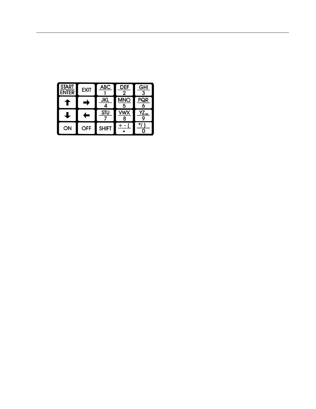
Using the Keypad................................................................................................................................ 3-2
Key Function....................................................................................................................................... 3-3
File Menu............................................................................................................................................ 3-3
Installation of the Battery.................................................................................................................... 3-4
Interpretation of Parameters ...................................................................................................................... 4-1
System Setup / Calibration ........................................................................................................................ 5-1
Calendar and Time Setup.................................................................................................................... 5-3
Leaf / Air Temperature Sensor ........................................................................................................... 5-3
Atmospheric Pressure ......................................................................................................................... 5-4
Flow Rate............................................................................................................................................ 5-4
CO2 and H2O....................................................................................................................................... 5-5
Data Transfer............................................................................................................................................. 6-1
Downloading Data .............................................................................................................................. 6-1
Selecting Files to Download ............................................................................................................... 6-2
Updating Software .............................................................................................................................. 6-2
A Sample Data File............................................................................................................................. 6-3
Photosynthesis, Transpiration and Stomatal Conductance........................................................................ 7-1
Absolute .............................................................................................................................................. 7-1
Taking Measurements......................................................................................................................... 7-1
Closed and Open Systems................................................................................................................... 7-4
Data Display Screens .......................................................................................................................... 7-6
Graph Mode ........................................................................................................................................ 7-7
Care of the CI-340..................................................................................................................................... 8-1
Leaf Chamber – Care and Use................................................................................................................... 9-1
Recharging............................................................................................................................................... 10-1
To Power your CI-340 From a Lab Power Socket ........................................................................... 10-1
To Disconnect the Charger/Adapter ................................................................................................ 10-2
To Charge the Li-ion Battery ........................................................................................................... 10-2
Battery Charger Specifications ........................................................................................................ 10-3
Equations................................................................................................................................................. 11-1

3/31/2008 Rev. 4.4 ii
Trouble Shooting..................................................................................................................................... 12-1
System Specifications ............................................................................................................................. 13-1
Power Pack / Accessory Bag................................................................................................................... 14-1
Accessory Control Port and Cable .................................................................................................... 14-2
Appendix A Temperature Control............................................................................................................ A-1
CI-510CS Temperature Control Module ........................................................................................... A-1
Filling the Reservoir .......................................................................................................................... A-2
Emptying the Reservoir ..................................................................................................................... A-3
Operating Temperature Control Module............................................................................................A-4
Appendix B CI-301LA Light Attachment Module ...................................................................................B-1
Appendix C CI-301AD Adjustable H2O and CO2Control Module ..........................................................C-1
General Description ............................................................................................................................C-1
Operating Instructions.........................................................................................................................C-1
Adding Consumables..........................................................................................................................C-1
Connection to Power and the Analyzer...............................................................................................C-2
Operation ............................................................................................................................................C-3
Replacing The Consumables...............................................................................................................C-3
Soda Lime.............................................................................................................................C-3
Silica Gel ..............................................................................................................................C-4
Water ....................................................................................................................................C-4
CO2Cartridge .......................................................................................................................C-4
Filters....................................................................................................................................C-4
Appendix D Soil Respiration Chamber.................................................................................................... D-1
Setup Procedures................................................................................................................................ D-1
Appendix E Canopy Chamber – Assembly Instructions........................................................................... E-1
Appendix F CI-510CF Chlorophyll Fluorescence Module ....................................................................... F-1
Connecting the CI-510CF Chlorophyll Fluorescence Module to the CI-340 Main Unit................... F-1
CI-340 Fluorescence Saturation Pulse Measurement ......................................................................... F-1
Specifications...................................................................................................................................... F-3
Warranty

INTRODUCTION
3/31/2008 Rev. 4.3 -1
INTRODUCTION
The CI-340 Ultra-Light Portable Photosynthesis System is an improved version of the first
lightweight, hand-held photosynthesis system in the world. Featuring a new design concept and
compact solid-state structure, the entire system – display, keypad, computer, data memory, CO2/H2O
gas analyzer, flow control system and battery – is contained in a single, hand-held case. It has
everything to measure photosynthesis, transpiration, stomatal conductance and internal CO2. Because
the chamber is connected directly to the CO2/H2O differential gas analyzer, there is virtually no time
delay when measuring CO2/H2O in the chamber. These features make the CI-340 the fastest,
smallest, and most accurate photosynthesis system available for field and laboratory operations.
The unit is designed to perform the following functions: Absolute, Calibrations, Data Transfer, and
Photosynthesis, Transpiration, & Stomatal Conductance. A brief overview for each function is
described in Table 1-1, and covered in detail throughout the manual.
Table 1-1. Description of CI-340 functions:
Absolute CO2 concentration measurement (in ppm) for a
single source
Calibrations Permits the user to calibrate the instrument with
various parameters or settings
Data Transfer Transfers data from the CI-340 to a computer
Photosynthesis, Transpiration, & Stomatal
Conductance
Measurements obtained by using Leaf Chamber
attachments(s) in conjunction with the CI-340
TECHNICAL SUPPORT
If you have a question about the CI-340 features and functions, first look in the CI-340 Instruction
Manual. If you cannot find the answer, you can contact a Technical Support Representative located
in your country.
CID, Inc. is committed to provide customers with high quality, timely technical support. Technical
support representatives are available on a 1-800 line to answer your technical questions.
CID, Inc.’s Address: CID, Inc.
4901 NW Camas Meadows Drive
Camas, WA 98607 USA

INTRODUCTION
3/31/2008 Rev. 4.3 -2
Phone: 800-767-0119 (U.S. and Canada)
360-833-8835
Fax: 360-833-1914
Internet: http://www.cid-inc.com
E-mail: [email protected]
CUSTOMER SERVICE:
Customer Service Representatives answer questions about specifications and pricing, and sell all of
the CID, Inc. products.
Customers sometimes find that they need CID, Inc. to make a change to upgrade their system, or
repair their system. In order for CID, Inc. to do these services, the customer must first contact us and
obtain a Return Merchandise Authorization (RMA) number. Please contact a customer service
representative for specific instructions when returning a product.

TECHNICAL INFORMATION
3/31/2008 Rev. 4.3 2-1
TECHNICAL INFORMATION
The CI-340 is a highly technologically advanced photosynthesis system. It contains a pump along
with a mass airflow sensor. A built-in microprocessor regulates the airflow rate, which is set by the
user. A technical diagram (Figure 2-1) illustrates a flow chart for this instrument. An illustration of
the CI-340 is on the following page (Figure 2-2).
The measurement process begins with an air/gas sample passing a solid-state CO2analyzer. The
output of the analyzer is amplified, sampled by an analog-to-digital (A-D) converter, and sent to the
microprocessor. The processor averages these readings and corrects them for any non-linearity
present in the analyzer.
A relative value of CO2concentration is continually updated by the microprocessor. Each reading
reflects sampling taken every second during a specified time period. This can be determined by
setting the time interval. The rate at which samples are saved in memory is determined by the
“sampling rate” or the time interval input at the beginning of each measurement session.
CAUTION: When attaching a pressurized gas source to the external inlet, use a three-way fitting
(which is provided with each instrument) to allow excess gas to escape. Excess pressure may blow
out internal fittings and tubing, or damage the pump. Do not use a three-way fitting for non-
pressurized gas sources.
Figure 2-1. Flow chart diagram.

TECHNICAL INFORMATION
3/31/2008 Rev. 4.3 2-2
Figure 2-2. Parts of the CI-340

GENERAL OPERATING INSTRUCTIONS
3/31/2008 Rev. 4.3 3-3
GENERAL OPERATING INSTRUCTIONS
This section will familiarize you with start-up procedures and guide you on how to move from one
function to another. Specific instructions for each separate function will be found under their
individual heading in the main body of the manual.
For greatest accuracy, the instrument should be turned on 30 minutes prior to any calibrations to
allow it to be fully warmed up. Measurements can be made about 3 minutes after the displayed CO2
value starts to drop from its maximum.
1. The instrument needs to warm up awhile before it is used to measure. The warm up is measured
from the time the instrument is powered on (it does not matter if it is measuring or not). A warm up of
about 4 minutes would be the minimum time to get measurements and about 20 minutes for more
precise measurements.
It is best to put the leaf into the chamber before you start the measurement so the leaf has time to
acclimate to the leaf chamber conditions and the instrument has time to react to the changes the leaf
causes. The "Working" display is a period that the instrument uses to stabilize itself. The actual
measurement starts when the display changes from "Working".
2. Variations in the CO2 readings or Pn readings can often be caused by changes in the air stream
going into the instrument. The CO2content of the stream must be very stable. Some researchers use
a long tube to get the intake away from human activity. Some use compressed air (with a pressure
regulator and a T in the hose). Some use a volume buffer (a 2 liter bottle or larger with the hose from
the instrument drawing air from inside that is vented to allow outside air in) that will average out CO2
changes over time. If the experiments are done near a road with vehicles, it is difficult to get stable
CO2readings. If you do not have a source of compressed air, you may try putting several volume
buffers in series (the instrument draws from the first bottle that draws from the second which then
draws from the third which is vented) The instrument is sensitive enough to detect fires that are
hundreds of meters away if they are upwind.
3. The flow rate can be reduced when the photosynthesis is minimal. Try 0.3 lpm for most situations
and 0.25 lpm if the readings are low.

GENERAL OPERATING INSTRUCTIONS
3/31/2008 Rev. 4.3 3-4
USING THE KEYPAD
The keypad for the CI-340 consists of 20 keys to enter commands and data. Figure 3-1 illustrates the
keypad.
Figure 3-1. CI-340 Keypad
Pressing a key makes a “beeping” sound. A key should be pressed individually each time a command
or letter is asked for. Refer to the TROUBLESHOOTING chapter if problems occur.

GENERAL OPERATING INSTRUCTIONS
3/31/2008 Rev. 4.3 3-5
These characters are not usable: [ +,-,(,*,/,) ]
FILE MENU
The CI-340 has a file system that allows a great range of data to be stored internally. It has been
designed to emulate the familiar DOS of personal computers. Note that this menu will not be
accessible when there are no files stored in memory; the message “no files” on the top display line
will be briefly displayed when this situation occurs.
To use the File Menu or check if any files are stored, press the key when “ENTER →file
menu” is displayed. Press the key to access the “file menu” when the instrument is first turned
on.
Enter →File menu 13:05:49
Use the and keys to view all stored files. Pressing the key will exit this menu.
Files are stored in chronological order, with the names and data affiliated accordingly. Up to 1200
files or 4 MB of data are allowed for storage. Press the + key (for the letter “D”) to

GENERAL OPERATING INSTRUCTIONS
3/31/2008 Rev. 4.3 3-6
delete the last file saved, or + key (for the letter “Y”) to delete all files saved. The shift
and keys will have to be pressed again to confirm erasure of all files. Deleting a file removes it
permanently! Be sure to transfer important data before deleting it from the CI-340. Refer to the DATA
TRANSFER section for related information.
INSTALLATION OF THE BATTERY
The CI-340 is dependent upon a properly charged power source for efficient and reliable
measurements and calculations. The included battery/battery eliminator is designed to provide the
necessary power. The system is designed to operate from 7.2V rechargeable Li-Ion batteries. Check
with the nearest representative or manufacturer if the included system does not include one or more of
the above items.
If the rechargeable battery should ever fail to charge properly, please recycle it. Many waste
processing systems do not allow Li-Ion batteries to be simply thrown in the trash.
Proper installation of the battery is as follows:
•Align the contacts of the battery with the contacts of the CI-340 (Figure 3-2).
•Line up the battery so that it is about 7 mm “off” its final position within the battery mounts in the
direction shown in Figure 3-2.
•Press the battery toward the contacts and slide in the direction shown (Figure 3-2) until firmly in
place. By pressing the battery toward the contacts, the CI-340 will make necessary connections
with the battery and the battery will be in the correct position.
•To remove the battery, slide it in the opposite direction that is shown in Figure 3-2.
Refer to the RECHARGING chapter for further information on how to take care of the battery and for
how to power the CI-340 in the lab without using the Li-ion battery.
Note: The CI-340 should only be used in low RF ambient areas. Do not use near radio/TV
transmitting antennas or near electrical arc welders.
Figure 3-2. Battery installation: Press the battery toward the contacts.

INTERPRETATION OF PARAMETERS
3/31/2008 Rev. 4.3 4-1
INTERPRETATION OF PARAMETERS
CO2(in) The amount of CO2(in ppm) at the inlet of the analyzer
CO2(out) The amount of CO2(in ppm) at the outlet of the leaf chamber
CO2(dif) The difference between the CO2in and CO2 out values.
H2O (in) The amount of H2O (in kPa) at the inlet of the analyzer
H2O (out) The amount of H2O (in kPa) at the outlet of the leaf chamber
H2O (dif) The difference between the H2O in and H2O out values.
PAR Photosynthesis Active Radiation in terms of цmol/m2/s
FLOW The set flow rate of the analyzer (in lpm)
W Mass flow rate in terms of mol/m2/s
T (air) Temperature of the ambient air (in °C) in the leaf chamber. This
requires the temperature sensor to be installed for meaningful results.
ATM Atmospheric pressure (in kPa)
Pn Net photosynthesis rate in terms of цmol/m2/s
InTCO2Internal CO2 цmol/mol
T (leaf) Temperature of the leaf as measured by infrared temperature sensor
(in °C)
C Leaf Stomatal conductance mmol/m2/s
Internal T Temperature of the analyzer environment (in °C)
E Transpiration Rate mmol/m2/s
“EXIT to quit” Aborts current operating function to the default menu
“ENTER →file menu” Allows the user to enter the file menu system:
“SHIFT 2 (D) = del” Command to delete an existing file; press +
“EXIT file menu” Returns to the default menu
“Y = delete ALL” Command to delete all existing files; press + . This must
be confirmed before the instrument will erase all the files.
“Date” Current running date
“Time” Current running time
“START/ENTER to go” Reminds the user that pressing will start the measurement
process.
“ENTER to select” Notifies the user to press to perform the listed functions:
“Change clock” Allows the user to change the time and date settings
“Calibrate CO2” Allows the user to calibrate the zero and span for CO2measurements.

INTERPRETATION OF PARAMETERS
3/31/2008 Rev. 4.3 4-2
“Calibrate H2O” Allows the user to calibrate the zero and span for H2O measurements
using external sources
“Calibrate Temp” Allows the user to set the TSCAL1 and TSCAL2 parameters of the
temperature sensor.
“Calibrate Flow” Allows the user to calibrate the flow meter to external standards.
“Calibrate ATM Pr” Precisely adjusts atmospheric pressure (in kPa)

SYSTEM SETUP / CALIBRATION
3/31/2008 Rev. 4.3 5-1
SYSTEM SETUP / CALIBRATION
The system is shipped from the factory calibrated for immediate use. The user can perform most
system calibrations if necessary.
To start the CI-340, press . After a brief warm-up time, the instrument will display the basic
display as follows:
Fri 12 Mar 2004 16:06:38
CI-340 version 5.004
©Copyright CID Inc., 1997 - 2004
All rights reserved.
The following screens are accessed in order by pressing the arrow keys, to move up and
to move down:
ENTER to select Calibrate Temp.
ENTER to select Calibrate Flow
ENTER to select Calibrate ATM Pr
ENTER->file menu
Starting Screen: Fri 12 Mar 2004 16:06:38
START/ENTER to go 16:06:38
ENTER to select Change clock

SYSTEM SETUP / CALIBRATION
3/31/2008 Rev. 4.3 5-2
ENTER to select Calibrate CO2
ENTER to select Calibrate H2O
CALENDAR AND TIME SETUP
The purpose of these functions is to provide the user current information of local date and time. This
method can be extremely useful to further establish when measurement data are collected or saved, or
simply another form of time keeping. The factory-calibrated date and time are the default values.
ENTER to select Change clock
To change the date and time, scroll to choose “Change clock” under the “ENTER to select” function
(press the key twice from the initial display). The time function will be the first selection. Begin
by using the or keys followed by the or keys to adjust and move to the hour,
minute and second of choice. With the time function set, the date function will follow. Once again,
use the or keys followed by the or keys to adjust and move to the month, day
and year of choice. Press the key to save your selection and continue. Note that at any point of
this setup, pressing the key will suspend any further actions and return to the screen display
above.
LEAF/AIR TEMPERATURE SENSOR
Suggested Calibration Schedule: None.
This function sets the calibration values for a given leaf/air temperature sensor. The included
temperature sensor has been initially tested and calibrated by the manufacturer.
ENTER to select Calibrate Temp
No further calibration is allowed.
ATMOSPHERIC PRESSURE
The CI-340 pressure sensor is capable of measuring absolute atmospheric pressure. This value is used

SYSTEM SETUP / CALIBRATION
3/31/2008 Rev. 4.3 5-3
in calibrations for Photosynthesis, Transpiration and Stomatal Conductance values. The sensor is
calibrated at the factory, and normally does not need to be recalibrated.
ENTER to select Calibrate ATM Pr
To change the atmospheric pressure (ATM) value, scroll to choose the “Calibrate ATM Pr” under the
“ENTER to select” function. Enter the desired ATM value in K Pa. Press to accept the entered
value or to abort the process, and continue to another step.
FLOW RATE
Figure 5-0
The CI-340 is capable of maintaining a steady airflow once the unit begins taking measurements.
After the initial warm-up time (one minute), the instrument will generate the entered flow rate to
regulate the accuracy of the measurements. The instrument is capable of automatically controlling the
flow rate from 0.2 ~ 0.999 lpm. Flow rates of 0.3 lpm give increased accuracy to photosynthesis
measurements unless very active leaves are being measured.
The flow meter is calibrated by the manufacturer but can be calibrated again by the user. Suggested
calibration schedule is once every six months. Scroll to choose the “Calibrate flow rate” under the
“ENTER to select” function.
ENTER to select Calibrate flow rate
The instrument will briefly run through stabilizing steps and then ask the user to adjust the flow,
using the keys for major changes or the keys for minor changes, over steps
from .2 to 1 lpm. For calibration, the flow MUST be measured by the calibrated external flow meter
at the port on the end of the instrument where the leaf chamber plugs in (upper left part as you read
the keypad). For this calibration, the flow rate is measured at the input to the leaf chamber (see figure

SYSTEM SETUP / CALIBRATION
3/31/2008 Rev. 4.3 5-4
5-0). A well-calibrated flow meter with little backpressure should be used as the standard. If for any
reason an error was made during the calibration procedure pressing the key will also return
back to the beginning of the flow calibration procedure without saving any changes made. Once the
calibration procedure is competed, in a few moments the instrument will reset and return back to the
above screen display.
CO2 AND H2O
NOTE: For greater changes in ambient temperatures between sample measurements, it may be
necessary to recalibrate to CO2 “zero setting” at each temperature (i.e. O°C sample and 40°C sample).
Suggested calibration schedule: ZERO setting once a week for CO2 and H2O; SPAN setting once a
week for CO2. Check H2O once every six months.
This instrument allows calibration with a range of CO2from 100 to 1000 ppm, and H2O from 1 to 7.5
kPa.
ENTER to select Calibrate CO2
To change the calibration of CO2, scroll to choose the “Calibrate CO2” under the “ENTER to select”
function. While the instrument stabilizes to the setup state, it will first ask if you want to calibrate
zero.
Start to set zero, else Exit
Press the key to calibrate the zero or press the key to skip the calibrate zero function.
Use 0 ppm CO2gas Press START/ENTER
Connect dry nitrogen or soda lime and allow the zero ppm CO2gas (dry nitrogen or soda lime) to
flow for approximately one minute (three minutes for soda lime) prior to pressing the key to
flush the system completely. Always use a “T” connector. A small amount of flow out of the one-
meter tube ensures a sufficient quantity of gas is flowing to the system (see Figure 5-1) in the gas line
when supplying gas from a low-pressure regulator in order to avoid excessive flow through the
system. Alternately, use soda lime connected between the intake and exhaust with the small plastic
tube where the chamber usually goes to form a closed loop. (See Figure 5-2)

SYSTEM SETUP / CALIBRATION
3/31/2008 Rev. 4.3 5-5
Figure 5-1. Configuration using compressed gas.
After the system zero is established, use a gas with known concentration of CO2 to calibrate span.
Use the key to skip the “calibrate the span” setting.
Use known CO2
Press the key to proceed.
Enter the concentration of CO2in ppm at the following display:
Concentration ?
__ ppm
The known concentration should flow for approximately one minute.
Press to save your selection. The system will then return to the following screen display and
reset:
ENTER to select Calibrate CO2
H2O calibration follows similar procedures. Dry nitrogen gas or silicon gel can be used for the H2O
zero, and a known partial pressure of H2O is used for the known H2O. A “DOS” program is provided
to convert relative humidity and temperature to kPa partial pressure. Run RH2KPA.EXE under DOS
or in a DOS window on a PC. Windows XP will automatically launch a DOS window if you double
click on the file name in Windows Explorer.

SYSTEM SETUP / CALIBRATION
3/31/2008 Rev. 4.3 5-6
NOTE:H2O span setting should not be calibrated except once every six months. However, it is
suggested that it be checked often by conducting a photosynthesis test with the “loop back” tube in
place of a leaf chamber and sampling a known humidity of the atmosphere.
Figure 5-2. Configuration using Soda Lime for CO2 zero calibration.
Figure 5-3. Configuration using Silica Gel for H2O calibration.

DATA TRANSFER
3/31/2008 Rev. 4.3 6-1
DATA TRANSFER
DOWNLOADING DATA
One of the conveniences of this reliable data-collecting instrument is its portability. The CI-340 is
almost a small user-friendly computer that can be operated almost anywhere in the field. However,
data analysis and presentation can best be done on an external (desktop or laptop) computer.
To download data to an external computer, attach the CI-340 USAB Cable to both the CI-340 and the
computer’s USB port.
Downloading files from the CI-340 to the personal computer is accomplished with a Windows
program, C340DF.exe. It would be recommended that a separate directory exist for any of the CI-340
program files or data to be stored. Create a directory that can be recognizable or remembered for
continuous usage; for instance, the path C:\CI-340\. could be named to store and locate all related CI-
340 files and data. Refer to the computer manual(s) regarding setting up directory/paths for the
current operating system (such as in Windows). To install the software on your computer, run
setup.exe on the disk. You can use Windows Explorer to send a shortcut to your desktop, if desired.
Run the C340DF.EXE program
Turn on the CI-340
Select File, then Open to transfer a file to the computer
A longer file will take longer to start displaying data. You can select File then Save to save the data.
The default extension is .dat.
UPDATING SOFTWARE
The operation of the CI-340 is controlled by internal software code. The CI-340 is capable of
updating its software code without removing the cover. When updating becomes necessary, the
manufacturer will provide the software code (under warranty) to best operate the instrument. The
web address is www.cid-inc.com/software/CI-340. The file DL.exe automatically downloads code
programs. Be sure that these files are in the same directory as other CI-340 program files.
It is the best to copy all the software files provided on the disk to their own directory on the hard drive
before executing DL.exe. Connect the CI-340 USB cable. Run the DL.exe. program to download code
from the computer. Make certain that the the power is on to the CI-340. If the power does not stay
on, then press and hold the key on the CI-340 (a constant ‘beep’ sound may or may not be
heard). Select File, Open and highlight the code file (CI_340.S19), and press ENTER on the
computer to start the update. After approximately 10 ~ 15 seconds, the instrument will display DLC,
Table of contents
Other CID Measuring Instrument manuals