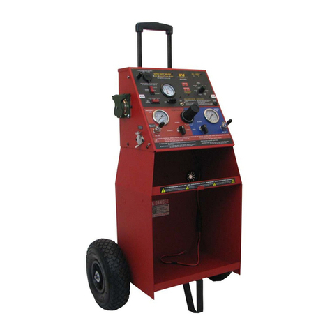
iPA ALPHA MUTT User manual

#5600-RTS Alpha MUTT®with ABS, Rugged
Tablet and Slide-Out Base
#5600A-S Alpha MUTT®with ABS and
Slide-Out Base
#5600A-RT Alpha MUTT® with ABS and
Rugged Tablet
#5602A Alpha MUTT® with ABS
(No Tablet or Slide-Out Base)
ALPHA MUTT®with ABS
Mobile Universal Trailer Tester
Set-Up Information • Operator’s Manual • Technical Information
For All Models
Innovative Products of America®Incorporated 234 Tinker Street, Woodstock, NY 12498
888-786-7899 | tech247@ipatools.com | www.ipatools.com

Congratulations on your recent purchase of an Alpha MUTT®Service-Truck
Model from Innovative Products of America®!
This binder provides information on the following Alpha MUTT®units:
•#5602A Alpha MUTT®with ABS
•#5600A-RT Alpha MUTT®with ABS and Rugged Tablet
•#5600A-S Alpha MUTT®with ABS and Slide-Out Base
•#5600A-RTS Alpha MUTT®with ABS, Rugged Tablet and Slide-Out Base
For questions or support, call 888-786-7899 or email tech247@ipatools.com.

FOREWORD
The AlphaMUTT®(Mobile Universal Trailer Tester) Service-TruckModelhas been thoroughly engineered
to provide the ultimate level of control and diagnostic troubleshooting capability when inspecting trailer
lighting, air brake and ABS systems. Your tester has been delivered “turnkey” with all the hoses, cables,
remote controls and tablet needed to begin testing. Be sure to read the entire set up and instruction
manual to ensure that all the benefits this tester can bring to your shop are utilized.
This Operator’s Manual has been created by Innovative Products of America®(IPA®) to provide users
with the necessary information to:
•Identify and understand the full capabilities of the tester.
•Recognize the safety precautions that should be adhered to during operation.
•Properly identify all parts, accessories and attachments included with the tester for
maintenance, operation, repair and replacement.
IPA®truly wants you to be 100% satisfied with your purchase. The Alpha MUTT®includes a 3-Year
Warranty and 24-Hour Repair or Replace Policy. Upon first receiving your tester, use the provided
unpacking sheet with included accessories kit for reference to specific accessories and features based
on your particular model. If you are missing any accessories, have questions or need assistance withany
step of the process, please call Tech Support at 888-786-7899 or email tech247@ipatools.com.
IPA®is also interested in hearing any suggestions you may have that could increase the productivity
and functionality of the Alpha MUTT®. If there isa feature you wish it had, please send us your feedback
and it may be included in the next update.
From all of us at IPA®, we thank you for your purchase and wish you and your family the very best
of everything.
Ian Vinci,
President
Innovative Products of America®

Introduction
1.1 Testing Functions ……………………...……………………………………...................
1.2 Registering Your Tester’s Warranty ……………….…………………......................…
1.3 Tester Identication ………………………………………………………......................
Tester Serial Number
Firmware Version Number
Software Version Number
1.4 Included Accessories ………………………...…….…………………......................…
1.5 Optional Accessories ……...……………………….………………..........................…
General Safety Instructions
2.1 Important Safety Information ……………...…..…...……………….........................…
2.2 Battery Gases, Tester Preparation and Tester/Charger Location …...................….
2.3 General Charger Usage …………………………………………….......................…...
Specications
3.1 Service-Truck Model ………………...…………………………….......................….....
3.2 Rugged Tablet ………………………………………………………………...................
Initial Set-Up
4.1 Battery/Power Supply Requirements ………………….................……………………
4.2 Installing Shop Air ………………….............……………………........................…..…
4.3 Truck-Box Installation (For -S Models Only) …………..............................................
Drilling Mounting Holes into the Service-Truck Box
Placing the Slide-Out Base into the Service-Truck Box
Bolting the Slide-Out Base into the Service-Truck Box
Installing 12V DC/Battery Connection
General Controls And Operations
5.1 Mechanical Functions ……………….......................…………….........................……
Auto Shutdown Feature
5.2 Control Panel …………………...........................................…………….....................
5.3 Right Side Panel …………………..........................................................................…
5.4 Lower Panel …………………..............................................................................…..
5.5 Remote Controls ……………………………………………………………...................
How to Program the 12-Button Remote
How to Use the 12-Button Remote
5.6 Tablet Controls ……………………………………………………………..................…
Tablet Buttons
Tablet Pen
Power Saving
Bluetooth®Connection (BLE)
How to Charge the RT Tablet with the AC Plug
How to Charge the RT Tablet while Mounted in the Storage Drawer
How to Check for Software Updates
Email to Tablet
Computer to Tablet
Direct to Tablet
Bluetooth®
6.1 Installing the Bluetooth®Communication Module ……………….…………..............
Direct Connection
Using an Extension Cable
6.2 Bluetooth®Helpful Tips …………………………………......………….............………
6.3 Bluetooth®Module FCC ……………………………………….…………............…….
TABLE OF CONTENTS
Part 1:
Part 2:
Part 3:
Part 4:
Part 5:
Part 6:
Pg.
1-1
1-2
1-3
1-4
1-5
2-1
2-1
2-2
3-1
3-2
4-1
4-1
4-2
5-1
5-2
5-4
5-6
5-7
5-8
6-1
6-2
6-2

Operating the Alpha MUTT®App
7.1 Application Setup …………………………………………………………............…….
Accounts
Company Information
Testing Defaults
7.2 Menu Bar Screens …………………………………………………………............……
7.3 Diagnostic Controls …………………………………………………………...........…..
Electrical/Lighting Testing
8.1 Pretest Checklist …………………………………………………………......................
Tester Placement
Maintain Connectors
Cable Testing Procedure
8.2 Selecting a Circuit ……………………………………………………............………….
Auto-Cycle Mode
8.3 Ground Integrity Test …………………………………….............……………………..
Chassis and Pin Grounds
Establishing a Chassis Ground
8.4 Fault Indication …………………………………………………………………..............
Open Circuit
Crossed Circuits
Short/Overloaded Circuit
8.5 Activating Hazard Lights ………………………………………………………..............
8.6 All Circuits On (Override) Mode ………………………………………………..............
Air Brake Testing
9.1 Testing Set-Up …………………………………………………………….....................
9.2 Actuating Air Brakes ……......................………………………………........................
9.3 Leak Down Testing ………………………………………………………......................
Manual Leak Down Test
Automatic Leak Down Test
Changing Automatic Leak Down Test Parameters
ABS Diagnostics
10.1 Accessing ABS Codes ………………………………………………...........................
ABS Explained
10.2 Manual Controls ………………………………………………………..........................
Accessing Active Faults
Accessing Stored Faults
Clear All Codes
10.3 Tablet Controls ………………………………………………………............................
10.4 Failure Mode Identier (FMI) Assignments ……………………….............................
10.5 SAE J1587 Mid 137 Sid List …………………………………………..........................
Inspections and Reporting
11.1 Electrical Inspections …………………………………………………..........................
Pass Result
Fail Result
11.2 DOT/PM Inspections …………………………………………………..........................
Truck Inspections Controls
Trailer Inspections Controls
11.3 Saved Reports ……………………………………………………….............................
11.4 Inspection Creator Tab ………………………………………………...........................
11.5 Sample Reports ………………………………………………………...........................
Updating Firmware
12.1 Updating Front Face Panel ……………………............................…………………...
12.2 Updating ABS Module ………………………………………….............................…..
Part 7:
Part 8:
Part 9:
Part 10:
Part 11:
Part 12:
7-1
7-2
7-3
8-1
8-2
8-4
8-5
8-6
8-7
9-1
9-2
9-4
10-1
10-2
10-4
10-5
10-6
11-1
11-4
11-7
11-8
11-9
12-1
12-1

Maintenance
13.1 Maintenance and Storage …………………………………….............................…….
13.2 Instructions for In- and Out-of-Warranty Repairs …………………..........................
Troubleshooting
14.1 FAQ ………………………………………………………………..................................
14.2 Common System Checks …………………………………………..............................
14.3 Common Troubleshooting Solutions ……………………………...............................
Exploded Views and Diagrams
15.1 Body Exploded View ………………………...............................................................
15.2 Face Exploded View ………………………......................……...............................…
15.3 Side-Panel Exploded View ………………………................................……...............
15.4 Storage Drawer Exploded View …………………………......................................….
15.5 Door Exploded View ……..........................................………………................…......
15.6 Slide-Out Base Exploded View ………………...............……………................……..
Part 13:
Part 14:
Part 15:
Pg.
13-1
13-2
14-1
14-2
14-3
15-3
15-5
15-7
15-9
15-11
15-13

Part 1
Part 1:
Introduction

PART 1: INTRODUCTION
The Alpha MUTT®is an all-in-one, mobile, advanced diagnostic tester and inspection system for both
vehicles and trailers. It saves time and money by providing mistake-free, paperless inspections that are
faster and more efficient than existing methodsacross all your locations. Innovative Products of America®
(IPA®) uses its own proprietary technology and a custom software suite to achieve unparalleled accuracy
and record keepingwhile conducting electrical, airbrake and ABS testing along with full DOT inspections.
While there are various models of the Alpha MUTT®available with different included accessories, all
products that feature the name Alpha are Bluetooth®and RF equipped and can be operated by both
tablet and RF remote control. The Alpha MUTT®is microprocessor controlled and features state of the
art current sensing, computer-controlled circuit protection, live circuit monitoring with automatic pass/fail
calculations, as well as digital voltage and amperage draw readout. The tester will detect poor grounds,
open circuits, crossed circuits, short circuits, and also features Pulsar®which aides in troubleshooting
intermittent and dead shorts. Models equipped with ABS diagnostics can be utilized to read and clear
codes and display troubleshooting information on a trailer via the 7-way connector. Those readings are
displayed on the face panel as well as through the tablet app
This manual covers the Alpha MUTT® Series technology. Please consult your specific model for your
exact list of included options. This product is backed by a 3-year warranty with 24-hour repair or replace
service. Should you run into any issues, please contact IPA® directly at 888-786-7899 or email
1.1 Testing Functions
•Electrical Testing (12/24 Volt Operation):
-Automatic cross, open, overload, short and ground fault detection
-Chase down short circuits with Pulsar®mode
-Cable testing
-Ground failure detection differentiates between wire and chassis ground
-Detailed inspection report generated from auto-test report function in under
60 seconds
•Air Brake Testing:
-Real-time, repetitive brake activation to find developing problems and verify
leaking servo cans
-Perform analog leak-down tests in service and emergency lines
•ABS Testing (A Models Only):
-Read and clear codes
-Displays diagnostic troubleshooting information
-Accesses ECU data: manufacturer, make, model, etc.
1-1

1.2 Registering Your Tester’s Warranty
Innovative Products of America®(IPA®) has established a Limited Three-Year Warranty Policy for the
Alpha MUTT®Series, not including any wearable parts, i.e., batteries (30-day warranty), battery clips,
etc.
Three-Year Limited Warranty/Return or Replace Policy: The product is covered for three years from
the date of original user purchase under the stipulations of the Standard Warranty.
The product is warranted to be free from defects in workmanship or material. If there is a problem due to
workmanship or material defect, IPA®will repair or replace the product within 24-working hours after it is
received by the IPA® repair service center. In the event it is determined that the product has been
tampered with or altered in any way, the warranty is void and all claims against the product will not be
honored. The warranty repair/return procedures require that the proof of purchase must be established
(either by warranty card from the seller or by point of purchase receipt/invoice) and the manufacturer
makes every attempt to return ship the product within three business days from the receipt of the returned
product, freight prepaid. If it has been determined that the tool has been damaged due to misuse, IPA®
will repair the tool at a cost we deem reasonable, and these charges will be the responsibility of the user.
We truly want you to be happy with our products, so if you have any questions, call us toll free at
888-786-7899.
There are three options for registering your tester for warranty:
•Complete the included warranty card found in
the front pocket of this binder and mail it to:
Innovative Products of America
234 Tinker Street
Woodstock, NY 12498
•Complete the online warranty registration at
www.ipatools.com/warranty-returns/.
•Complete your registration on the Alpha MUTT®
App under the SETTINGS section.
(Currently unavailable)
OR
OR
1-2

1.3 Tester Identification
Tester Serial Number
Can be found on the side of the tester.
Firmware Version Number
The Firmware version number will display on the
LCD Menu Screen when you power the tester on.
Software Version Number
Can be found on the top right corner of any
screen while in the Alpha MUTT®App.
1-3

1.4 Included Accessories
Image
Part #
Description
Location
Included In
#MUT-RM12
12-Button
Remote with
Lanyard
Remotes and Battery
Accessories Nylon Bag
All Models
#5700-TABRT
Rugged Tablet
Docking Station Inside
Storage Drawer
#5600A-RTS
#5600A-RT
#5700-MNTRT-AS
Mount for
Rugged Tablet
Inside Storage Drawer
#5600A-RTS
#5600A-RT
#CBL-9INUSBMIC
Micro USB Cable
Connected to Tablet
and Tester Face
#5600A-RTS
#5600A-RT
#5700-TABCH
Tablet Charger
Remotes and Battery
Accessories Nylon Bag
#5600A-RTS
#5600A-RT
#5700-BT-AS
Bluetooth®
Antenna
Inside Storage Drawer
All Models
#CBL-OBD2EXT
6’ Bluetooth®
Antenna
Extension Cable
Remotes and Battery
Accessories Nylon Bag
All Models
#7900K-1-12AS
20’ 7-Way Cable
Box 2 of 3
All Models
#7900AP-12RED-FX
#7900AP-12BLU-FX
20’ Gladhands
with Handles
Box 3 of 3
All Models
#5600-PWRCBL-AS
Power Cable
Remotes and Battery
Accessories Nylon Bag
All Models
X
#5600-SLDBASE-AS
Sliding-Base
Service Tray
Bottom of Unit
#5600A-RTS
#5600A-S
1-4

1.5 Optional Accessories
Image
Part #
Description
Includes
Optional For
#7900K-1-50-AS
50’ 7-Way Cable
X
All Alpha Models
#5705-HS50
50’ Gladhands with
Handles
X
All Alpha Models
X
Rugged Tablet
Upgrade
Rugged Tablet,
Docking Station,
Hardware
#5600A-S
#5600A-NT
#5600-NT
X
Sliding-Base
Service Tray
Upgrade
Sliding-Base
Service Tray,
Hardware
#5600A-RT
#5600A-NT
#5600-NT
1-5

Part 2
Part 2:
General Safety
Instructions

PART 2: GENERAL SAFETY INSTRUCTIONS
2.1 Important Safety Information
It is important to read, understand and follow all safety messages and instructions printed in this
manual and on the equipment before operating. If safety information is not heeded, serious injury
or death to the operator or bystanders may occur.
Danger
Indicates a hazardous situation, if not avoided, will result in death or serious injury. The possible hazards
are shown in the adjoining symbols or explained in the text.
Warning
Indicates a hazardous situation, if not avoided, could result in death or serious injury. The possible
hazards are shown in the adjoining symbols or explained in the text.
Caution
Indicates a hazardous situation, if not avoided, may result in minor or major injury. The possible hazards
are shown in the adjoining symbols or explained in the text.
The following safety alert symbols are used in this manual.
Symbol 1: Potential burn hazard. Sparks from electrical shorts can ignite flammable liquids such as
fuel or oil. Heat from electrical overloads can cause fire hazards.
Symbol 2: Potential electrical hazard. Batteries have enough electrical energy potential to ignite
flammable liquids such as fuel or oil. Wire overloads can cause electrical failures. Shock hazard exists.
Symbol 3: Potential explosive air hazard. Pneumatic pressures used with this equipment can cause
explosive failures on damaged equipment.
Symbol 4: Potential eye hazard. Wear OSHA approved safety glasses. Battery acid and high air
pressures create hazardous situations for eyes.
Symbol 5: Potential chemical burn hazard. Wear protective gloves. Battery acid is corrosive and can
cause skin damage.
Symbol 6: Potential electrical hazard. Electrical energy can cause heat and burn hazards.
Symbol 7: Potential fire hazard. Use caution with flammable liquids such as fuel and oil. Electrical
shorts can ignite flammable liquids and wiring.
Symbol 8: Important information is stated.
2.2 Battery Gases, Tester Preparation and Tester/Charger Location
Risk of Explosion
•Gases produced by a battery are highly explosive.
•Wear safety goggles and protective clothing, both users and
bystanders.
•Use in an area having at least four air changes per hour.
•Read, understand and follow all instructions for charger, battery, vehicle and any equipment used
near battery and charger.
•Do not smoke, strike a match, place metal tools on battery or cause a spark in the vicinity of
the battery. When removing battery cables, remove the ground cable first.
2-1

•Clean terminals before charging battery. Keep corrosive particles from eyes, nose and mouth.
Use baking soda and water to neutralize acid and help eliminate airborne corrosion.
•Never allow clamps on charger cables to touch each other.
•Do not expose tester or charger to rain, snow or wet conditions.
•Do not allow battery gases or acid to contact MUTT®cabinet. Do not place charger directly above
or below battery.
•Fill battery to level specified by battery manufacturer using distilled water.
•Do not remove cell caps while charging per manufacturer’s instructions.
•Make sure tester cable clamps make tight connections.
•Battery explosion can cause injury.
2.3 General Charger Use
Risk of Electric Shock and Fire
•Before connecting charger cable to tester, make sure controls are set to OFF.
•Do not remove or bypass the grounding pin.
•Do not operate charger with damaged cord or plug. Replace immediately if damage occurs.
•Position power cord and charger cables away from the hood, doors and hot or moving engine
parts where they could be damaged.
•Unplug power cord by grasping and pulling on the plug, rather than the cord when disconnecting
charger from outlet.
•Charger power cord uses an equipment-grounding conductor and a grounding plug. Plug only into
a 120V AC outlet that is correctly installed and grounded in accordance with all ordinances and
local codes.
•Unplug power cord from outlet before cleaning or maintaining tester and charger. Turning off
controls does not reduce the risk of electric shock.
•Do not operate charger after a sharp impact, drop or any other damage. Do not disassemble.
•Use only recommended attachments.
•Do not charge a frozen battery. Do not overcharge a battery.
•Use charger only on lead-acid automotive batteries. Do not use charger to charge dry-cell
batteries.
•Electric shock or fire can cause injury.
Risk of Entanglement
•Keep yourself, clothing and battery charger leads clear of moving parts such as fan blades,
pulleys, hood and doors. Moving parts can cause injury.
Risk of Burns
•Batteries can produce a short circuit current that is high enough to weld jewelry such as rings,
bracelets and watches. You must remove them before working near batteries.
•Short circuits can cause injury.
2-2

Part 3:
Specifications
Part 3

21.5”
PART 3: SPECIFICATIONS
3.1 Alpha Mutt®Service-Truck Model
Specifications:
Connection Type: 7-Way Round Pin
Power Input: 12/24V DC
Ammeter: 5mA –21A
Source Output: 20A @ 12/24V DC
Max. Op. Pressure: 120 psi
Air Input: 1/4" npt (120 psi max.)
Controls: Tablet, Remote or Manual
Tablet: Android Operating System
Bluetooth®: 4.0 or Newer Equipped
Microprocessor: 2020 High-Speed
Displays: Dual-Line, 32-Character, All Environment Digital LCD Screens
Door: Steel with Magnetic Weather-Proof Strip
Faceplate: Waterproof and Sealed
Buttons: Illuminated Pushbutton Switches
Storage Drawer: Soft-Close with Docking/Charging Station for Tablet and Custom Foam Cutouts
Feet: Vibration-Dampening Rubber Mounts
Materials: 16-Gauge Powder-Coated Steel Construction
Weight: With Base –54 lbs. / Without Base –46 lbs.
Dimensions: With Base –16.5" W x 21.5" H x 19" D (33” Extended)
Without Base –15.5” W x 19.5” H x 17” D
3-1

3.2 Military-Grade, Rugged Tablet (Available with RT Models)
Specifications:
Operating System: Android 7.1
Screen Size: 8.0"
Display Resolution: WXGA (1280 x 800)
Touch Screen: Wet-Touch/Glove-Touch Modes, Stylus Included
Memory: 16GB (Internal) Micro SD (Up to 256GB)
Connector: Pogo Pin (Wireless, Quick Charging)
Bluetooth®: v.4.2
Battery Type: Li-Polymer (Replaceable)
Battery Life: Up to 11 hrs.
Sensors: Face Recognition, Accelerometer, Fingerprint, Gyro, Geomagnetic, Hall,
RGB Light, Proximity
Ruggedness: IP68 (Water and Dust Resistant), Anti-shock (Drop from 1.2m Height with Cover)
Certifications: MIL-STD-810G, EPEAT, Energy Start, TCO, RoHS
3-2

Part 4
Part 4:
Initial Setup

PART 4: INITIAL SET-UP
4.1 Battery/Power Supply Requirements
The Alpha MUTT®is a 12/24V DC device. Attempting to power the
MUTT®with anything other than a 12- or 24-volt DC power source
will destroy the internal circuitry and void the warranty.
•The Alpha MUTT®Service-Truck Model requires an external
DC power source to function. A Group 31 or similar battery is
recommended.
•The Service-Truck Model does NOT have a built-in charger.
•The battery in the service truck must be maintained at a voltage between 12- and 14.5-volts DC.
Typically, batteries wired in parallel with the vehicle's own battery system will suffice.
•If running a dedicated power wire from a vehicle's main batteries, a 10-gauge wire is recommended
for runs up to 40’and an 8-gauge wire is recommended for runs longer than 40’.
•All wiring must be able to carry a sustained current of 21 amps at 12V DC.
•An external(2pin) DC power connector is provided with the tester. Thatpower connector terminates
to a 2 prong SAE connector. A mating SAE connector on a 3’cable with bare ends is also provided.
This cable can be used to make the connection to the vehicle's battery or dedicated wires.
•Follow standard battery wiring procedures. RED indicates Positive and Black indicates Negative.
When a cable has two black leads, if one lead has a white stripe, that lead is Positive.
•Prior to making connections, verify proper voltage orientation from the vehicle using standard
Automotive Style Volt Meters.
•The DC power connections require routine preventive maintenance to avoid downtime. The two-
prong connector should be disconnected and inspected once per month. Pins should be checked
for corrosion on both the cable and tester sides. If corrosion is present, clean connectors using
IPA®’s patented CLR156 Terminal Cleaners. Then clean the connections using IPA®8035A
DeoxIT®contact cleaner. Replace connector if needed. Check replacement parts section of this
manual for all related components.
4.2Installing Shop Air
1. Be sure to leave an additional 18” of air-line length so the tester can
be pulled out via the slide-out base without damaging the air input.
A 3/8” OD coiled air hose extension is recommended.
2. Locate the ¼” female NPT bulkhead fitting located near the
12V power input.
3. Install the male end of the air hose into the connector while firmly
holding a wrench onto the hex bulkhead to prevent any internal
components from becoming damaged.
WARNING: Listen for any air leaks where the shop air connects to the tester to avoid erroneous
results.
NOTE: It is always recommended to apply Teflon Tape to threads and then Pipe Dope over the
Teflon prior to assembling NPT fittings
12/24 Volt DC
Power Only
4-1
Table of contents
Other iPA Test Equipment manuals

iPA
iPA SMART MUTT X User manual

iPA
iPA LIGHT RANGER MUTT 9101 User manual

iPA
iPA 8010 User manual

iPA
iPA NATO MUTT M2000 User manual

iPA
iPA SMART MUTT 9004A User manual

iPA
iPA SMART MUTT 9004M User manual

iPA
iPA SUPER RANGER MUTT User manual

iPA
iPA 9102 User manual

iPA
iPA 9101 User manual

iPA
iPA Alpha MUTT 5700 User manual
Popular Test Equipment manuals by other brands

Tektronix
Tektronix TDS6604 Service manual

UEi
UEi NCV3 instruction manual

Chicago Electric
Chicago Electric 90636 operating instructions

Tektronix
Tektronix 7613 instruction manual

Bacharach
Bacharach FYRITE Gas Analyzer CO2 and O2 Indicators operating & maintenance manual

PeakTech
PeakTech 2755 Operation manual