SIL 112-61s User manual

STATUS TO ANALOGUE
CONVERTER
Type 112-61s
User Guide

Contents
Installation ....................1
Dimensions & fixings..................1
Wiring .........................2
Power supply considerations .............2
Access to terminals ..................2
Terminal connections...............2
Operation .....................3
Switch settings ..................3
Opening the module ..................3
Setting number of inputs ...............3
Test modes ......................4
Reassembly ......................4
Appendices
1 - Early versions with linear power supply ......5
2 - Specification ....................6
Doc Ref UD112-61S.vp Page 1
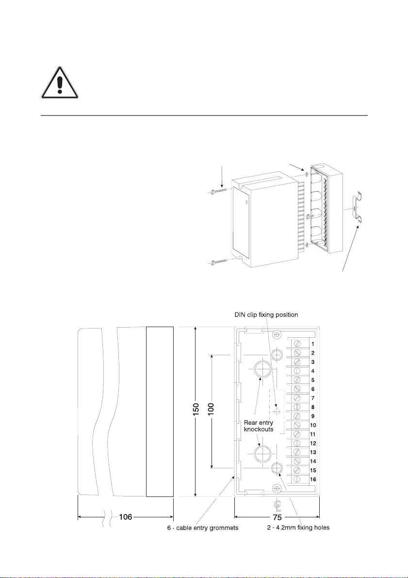
Installation
112 Series Modules are designed to be
fitted to any flat dry surface using two
4mm screws. Alternatively, by fitting an
optional DIN clip, they may be clipped to a
rail conforming to BS5584:1978,
EN50 022, DIN46277-3.
Grommets are provided on three sides of
the base section and there are two rear
entry knock outs in the bottom.
Plug in Module
Securing Screws
Screw Retaining Washers
Optional Din Clip
Dimensions in mm
IMPORTANT - Installation, wiring, commissioning or re-ranging of
this instrument should be restricted to authorised skilled personnel.
SWITCH OFF ALL POWER SUPPLIES AND ISOLATE SIGNAL WIRING
FROM DANGEROUS VOLTAGES BEFORE COMMENCING WORK ON
THE INSTRUMENT
Doc Ref UD112-61S.vp Rev 1 Page 2
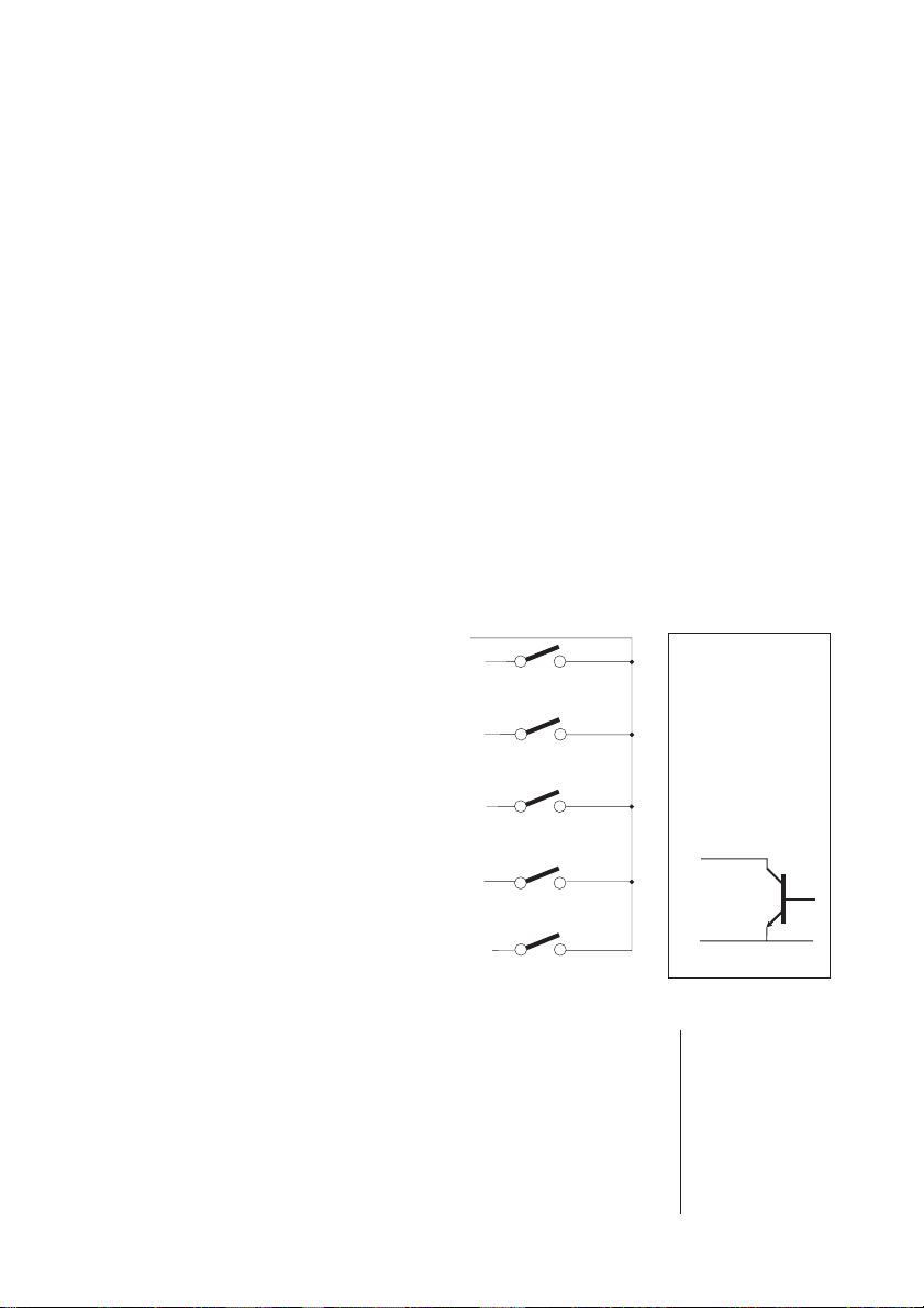
Terminal connections
Inputs
Voltage / current Volt-free contacts / open collector*
1 (+) 1
2 (--) 2 (+)
3 (+)
4 (--) 4 (+)
5 (+)
6 (-- ) 6 (+)
7 (+)
8 (-- ) 8 (+)
9 (+)
10 (-- ) 10 (+)
Outputs
Voltage or Current Sink Current
11 Output (--) 12 Output (--)
12 Output (+) 13 Output (+)
Supply DC Supply Option
14 Earth Earth
15 Neutral Negative (-- )
16 Line (85-265 Vac) Positive (+)
* for open collector
inputs (npn
transistor),
connections as for
volt-free contact
- emitter to
common, e.g.
Input A
Input C
Input B
Input D
Input E
Wiring
Grommets are provided on three sides of
the base section and there are two rear
entry knock outs in the bottom. Good
instrumentation practice should be
observed when wiring to the unit to
ensure segregation of mains supply and
signal wiring. Screened cables should be
used for signal / sensor wiring with the
screen earthed at one end only.
Power supply considerations
This instrument operates from an AC
supply in the range 85-260VAC 3VA - see
Appendix 1 for earlier versions with linear
power supply. Power supply wiring to the
instrument should be protected by a
suitable fuse and double-pole isolating
switch.
Access to terminals
Isolate all supplies to the unit. Loosen the
two module securing screws. (NB these
screws are retained in the top section by
2
1
NB Inputs and
outputs are
configured during
manufacture and
are not intended
to be changed by
the user.
common

Doc Ref UD112-61S.vp Page 3
Operation
Introduction
The 112-61s provides an analogue output
proportional to the number of active
inputs. Each unit will accept up to five
inputs but the outputs of multiple units
may be connected in series (voltage) or
parallel (current) for applications
monitoring more than five inputs - see
Note 2. below. The number of input
signals required for full scale output is set
by internal switches.
Notes:
1. Input and Output signal types are
configured during manufacture and
are not user selectable. Information on
the types set may be found on the
data label on the side of the enclosure
and the connection label on the
underside of the plug-in module.
2. In multiple unit configurations the
output signal range will have been
configured to suit the number of units
connected together. Connection
instructions will have been provided
separately.
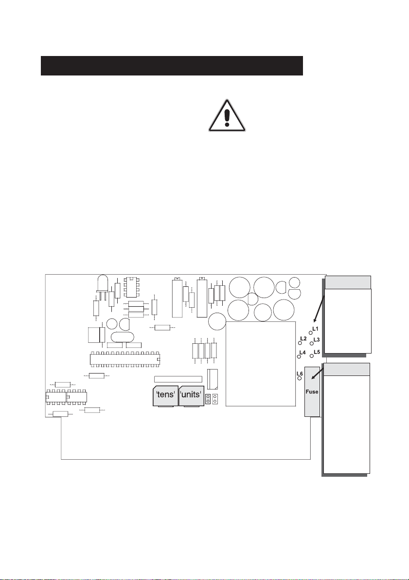
Switch settings
SWITCH OFF ALL POWER
SUPPLIES AND ISOLATE
SIGNAL WIRING FROM
DANGEROUS VOLTAGES
BEFORE PROCEEDING.
The number of intput signals required for
full scale output is set by internal switches
located on the printed circuit board - for
location see Fig 1. The switches may be
accessed as follows:
Opening the module
(i) Isolate all supplies to the unit.
(ii) Unscrew two module retaining screws
and separate the plug-in module from
the base section.
(iii) With the fingers, ease apart the longer
sides of the cover releasing the
interlocking tongue and groove
fastenings to remove the plastic plate
with the connections label.
(iv) Slide out the printed circuit board
(PCB) noting the location and
orientation of the PCB.
Setting number of inputs
Set the ‘tens’ and ‘units’ switches to the
number of inputs being monitored. For
applications where multiple units are
being connected to cater for more more
than five inputs, the switches in each unit
must be set to the total number of inputs
being monitored. e.g. to provide a full
scale output with 15 input signals present,
three Status to Analogue Converters
would be required, each set for 15 inputs.
NB see Note 2 under ‘Operation’.
captive washers). Gently pull away the top
section of the module from its base to
expose the fixing points and wiring
terminals. To refit the module, align the
module edge connectors with the socket
in the base and carefully press home.
NB Do not over tighten the module
securing screws.

Doc Ref UD112-61S.vp Rev 1 Page 4
Re-assembly
(i) Slide the printed circuit board into the
correct slot in the cover (i.e. ensuring
the LED indicator aligns with its
window in the front panel).
(ii) Replace the plastic plate by first
engaging the side with the two
tongues into their slots in the case
then press the plate home to engage
the single tongue.
(iii) Align the module edge connectors
with the socket in the base section
and press home.
(iv) Replace module securing screws but
do not over tighten.
Fig 1 Location of switches
‘Tens’ ‘Units’
Doc Ref UD112-61S.vp Page 5
Mains Supply
Supply voltage adjustment
Mains powered units can be adapted for
operation on 110V, 220V or 240V
supplies. The diagram below provides
details of the required link settings which
are effected by soldered tinned copper
wire links.
IMPORTANT: Links for 110V operation must
be insulated with silicon rubber sleeving.
NB: DC powered units are an option
specified at the time of ordering and have
no facilities for changing the operating
supply voltage.
SWITCH OFF ALL POWER
SUPPLIES AND ISOLATE
SIGNAL WIRING FROM
DANGEROUS VOLTAGES
BEFORE PROCEEDING.
240v link
2-3 & 4-5
220v link
2-5
110v link
2-6 & 1-5
Appendix 1 - Earlier versions with linear power supply
AC Supply
100mA
quick blow
DC Supply
12V -250mA
24V -250mA
48V -100mA
anti-surge
Fuse

Doc Ref UD112-61S.vp Rev 1 Page 6
Appendix 2 - Specification
INPUT SIGNAL OPTIONS
a) Contact closure (must sink 10mA approx.)
b) Open collector transistor (npn -must
sink 10mA approx.)
c) Voltages in the range >5V <50V
(external circuit must source 10mA approx.)
d) Current signals >10 <20mA
OUTPUT SIGNAL OPTIONS
(Others can be provided)
0-10 mA into 2000 ohms maximum
0-20 mA into 1000 ohms maximum
4-20 mA into 1000 ohms maximum
Current sink 4-20mA @ 30 volts maximum
0-5 Volts into 500 ohms minimum
1-5 Volts into 500 ohms minimum
0-10 Volts into 500 ohms minimum
ISOLATION
Maximum Voltage 250V RMS or 400V DC
For active inputs: each of the inputs and
the output are isolated from each other
and from the power supply.
For passive inputs: the input stage and the
output are isolated from each other and
from the power supply. However, inputs
are connected to each other via the
shared internal isolated 24 V transducer
supply.
TEMPERATURE RANGE
Operating: -10°C to +60°C;
Storage: -20°C to +70°C
POWER SUPPLY
Universal ac supply accepts 85 Vac to
265 VAC, 50/60Hz
Protected by a fusible resistor.
DC Supply Option:
24 VDC (18-36VDC) 3.5 W
Protected by a 250mA internal
self-resetting fuse.
DIMENSIONS
160 (H) x 76 (W) x 106 (D)
WEIGHT
Approx. 0.4kg
SAFETY & EMC
Safety: EN61010-1
Immunity: EN50082-1
Emissions: EN50081-1
CE certified
Table of contents
Other SIL Media Converter manuals


