Gomax MX-2000A User manual

Dual-View Video Processor with
Audio Path
User Manual
M
MX
X-
-2
20
00
00
0A
A
rev: 120518
Made in Taiwan

The MX-2000A Dual-View Video Processor with Audio Path has been tested for conformity to
safety regulations and requirements, and has been certified for international use. However, like all
electronic equipments, the MX-2000A should be used with care. Please read and follow the safety
instructions to protect yourself from possible injury and to minimize the risk of damage to the unit.
●Follow all instructions and warnings marked on this unit.
●Do not attempt to service this unit yourself, except where explained in this manual.
●Provide proper ventilation and air circulation and do not use near water.
●Keep objects that might damage the device and assure that the placement of this unit is on a
stable surface.
●Use only the power adapter and power cords and connection cables designed for this unit.
●Do not use liquid or aerosol cleaners to clean this unit. Always unplug the power to the device
before cleaning.
TABLE OF CONTENTS
INTRODUCTION.................................................................................................................1
FEATURES.........................................................................................................................2
PACKAGE CONTENTS......................................................................................................2
SPECIFICATIONS..............................................................................................................3
PANEL DESCRIPTIONS.....................................................................................................4
HARDWARE INSTALLATION.............................................................................................5
OPERATION SOFTWARE................................................................................................10
TROUBLESHOOTING......................................................................................................16
LIMITED WARRANTY ......................................................................................................17
APPENDIX –SUPPORTED RESOLUTION......................................................................18

1
INTRODUCTION
The MX-2000A Dual-View Video Processor with Audio Path is an advanced video processor for
multimedia presentations. It is an ideal solution for applications where two video signals must be
displayed on a single display. It supports up to four video inputs, of which two can be outputted simultane-
ously in Picture-In-Picture (PIP) or Picture-Aside-Picture (PAP) modes. The MX-2000A allows you to
manipulate output images, wherever position and whatever sizes you want for viewing two computers or
two video signals or a combination. Despite the advanced video features, MX-2000A also equips audio
processor allowing users to do analog switching and convert analog stereo into HDMI streams.
The embedded scaler converts signals from input sources to match the native resolution of monitors,
flat panel displays, projectors as well as user-selectable output settings up to WUXGA (1920x1200). Dual
outputs are provided in both analog (VGA) and digital (HDMI/DVI) format, one is connected to remote
display and the other is connected to on-site display for real time monitoring.

2
FEATURES
●Three graphic (DVI / VGA) and four video (HDMI /Component / S-Video / Composite) Inputs, from
640x480 to 1920x1200, interlaced or progressive.
●Dual video outputs (DVI / HDMI), 640x480 to 1920x1200, and YPbPr, HD 720p.
●HDCP 1.1 Support
●PIP, PAB, Full screen modes and adjustable size& position through software.
●Titles, borders and colored backgrounds.
●Resize, position, flip, zoom& pan and blend output video.
●Can be cascaded to obtain more images.
●Image parameters and layouts are automatically saved in flash memory and can be recalled for later
use.
●Several Image parameters and layouts can be saved in flash memory and can be recalled for later use.
●Video parameters adjustable (brightness, contrast, color temperature, etc.)
●User-selectable output settings, up to 1920x1200.
●Perfectly as a video screen splitter, a video converter and a video switcher.
●Analog audio switcher
●Analog stereo to HDMI audio conversion
●Hardware Fail-safe protection for YPbPr video and stereo audio path
●Firmware upgradable for support of new features and technology enhancements.
●IR control and software control through USB.
●Portable size.
●Automatically power-saving mode.
PACKAGE CONTENTS
●1x MX-2003B or MX-2000A ●1x 5V power adapter
●1x DVI to DVI&VGA breakout cable ●IR remote controller
●1x VGA to component breakout cable ●Installation software CD
●1x VGA to DVI adapter ●User Manual

3
SPECIFICATIONS
Model Name
MX-2003B
MX-2000A
Technical
Role of usage
Multiplexer / video processor
Dual output support
Yes [DVI + VGA]
Yes [HDMI/DVI + YPbPr]
HDCP compliance
Yes
Video bandwidth
HDMI/DVI [Single-link 4.95Gbps]
VGA [165MHz]
Component [30MHz]
S-Video/Composite [13.5MHz]
HDMI/DVI [Single-link 4.95Gbps]
VGA [165MHz]
Component [30MHz]
Composite [13.5MHz]
Input Video support
480i / 480p / 720p / 1080i / 1080p60 / 1920x1200@75 / 1600x1200@60
Audio support
No
Yes
Control
RS-232 and IR
USB and IR
PIP / PAP
Yes
Cascadable
Yes
Input TMDS signal
1.2 Volts [peak-to-peak]
ESD protection
Human body model —±19kV [air-gap discharge] & ±12kV [contact discharge]
PCB stack-up
6-layer board [impedance control —differential 100; single 50]
Input
2x VGA + 1x DVI/HDMI + 1x
component + 1x S-Video + 1x
composite + 1x RS-232
1x VGA + 1x DVI/HDMI + 1x
component +1x S-Video + 1x
composite + 1x USB +1x Stereo
Output
1x HDMI/DVI + 1x VGA
1x DVI + 1x YPbPr + 1 x Stereo
IR remote control
Electro-optical characteristics: = 25/ Carrier frequency: 38kHz
DVI connector
DVI-I [29-pin female, digital only]
VGA connector
HD-15 [15-pin D-sub female]
None
USB connector
Mini USB
RCA connector
75female
Mechanical
Housing
Metal case
Dimensions
[L x W x H]
Model
180 x 103 x 23mm [7.1" x 4" x 0.9"]
208 x 111.5 x 27mm [8.1" x 4.3" x 1.1"]
Package
330 x 200 x 95mm [1'1" x 7.9" x 3.7"]
325 x 196 x 92mm [1'1" x 7.6" x 3.6"]
Carton
495 x 440 x 380mm [1'7" x 1'5" x 1'3"]
490 x 426 x 352m [1'7.3" x 1'4.8" x 1'1.9"]
Weight
Model
480g [1.1 lbs]
680g [1.5 lbs]
Package
1345g [3.0 lbs]
1545g [3.4 lbs]
Fixedness
Wall-mounting case or wall hanging holes upon request
Power supply
5V 4A DC
Power consumption
10 Watts [max]
Operation temperature
0~40C [32~104F]
Storage temperature
-20~60C [-4~140F]
Relative humidity
20~90% RH [no condensation]

4
PANEL DESCRIPTIONS
The MX-2000A has four inputs and accepts both graphics and video signals, which come from
computers and NTSC/PAL video sources respectively. There is a concept of main channel and sub
channel for this device. You can choose two of the four inputs, one is for main channel and another is for
sub channel. Then display two of them simultaneously on the same screen. Figure 2 shows the rear panel
connectors of the MX-2000A; Table 1 illustrates how you can connect video devices and display to the
MX-2000A.
Side Panel
1. DVI/VGA input
2. S-Video and composite input
3. VGA input
4. Power connector
Rear Panel
5. USB 8. YPbPr output
6. Audio input 9. Audio output
7. DVI output 10. DIP switch* (for firmware & system reset)
* Default: Turn on the MX-2000A then switch both two DIP switches simultaneously up
and down to factory default mode.
*These IO ports support various resolution from 640x480 up to 1920x1200, for more detail
of the supported modes, please refer to the Appendix –Supported Resolution.

5
TABLE 1: I/O CONNECTORS
Input Connector
Video Source
DVI-IN
[1] DVI
[2] VGA —with a DVI-to-VGA adapter (DVA01)
[3] Component (YPbPr) —with a DVI-to-VGA adapter (DVA01) and a
VGA-to-component breakout cable (VYPBA01)
[4] 1x DVI + 1x VGA —with a DVI-to-DVI/VGA breakout cable (DDVY01)
[5] 1x DVI + 1x Component (YPbPr) —with a DVI-to-DVI&VGA breakout cable
(DDVY01) and a VGA-to-component breakout cable (VYPBA01)
VGA IN 2
[1] VGA —with a DVI-to-VGA adapter (DVA01)
Composite/S-Video
[1] Through a RCA cable
Output Connector
Display
DVI-I OUT
[1] HDMI/DVI display
YPbPr OUT
[1] Component display
HARDWARE INSTALLATION
Safety Precautions
1. To prevent fire or shock hazards, do not expose this device to rain or moisture.
2. When connecting other products such as DVD players, and personal computers, you should turn off
the power of this product for protection against electric shocks.
3. The product should be placed more than one foot away from heat sources such as radiators, heat
registers, stoves, and other products (including amplifiers) that produce heat. In addition, do not cover
any material or devices on the top of the device.
4. Do not use immediately after moving from a low temperature to high temperature, as this causes
condensation.
5. Do not place this product on an unstable cart, stand, or table. The product may fall, causing serious
injury to a child or adult and serious damage to the product.
6. Unplug this product from the wall outlet before cleaning. Do not use liquid cleaners or aerosol cleaners.
Use a damp cloth for cleaning.
7. Do not allow the same still picture to be projected for a long time or an abnormally bright video picture
to be projected. The video image could be burned in to the display device.

6
Installation Procedures
Unpacking
Remove the MX-2000A from the shipping container and examine it for any signs of shipping
damage or missing items (check with package contents above). All shipping items should be saved if the
product is to be moved or returned for service. Shipping unit back to dealers for service not in the original
box may result in voiding warranty or additional cost.
Placement
The unit uses convection to cool. A fan is not needed, so do not block the sides of this device or
stack another device on the top or bottom of the MX-2000A.
Connections
We recommend the highest quality cables for both input and output connections.
1. Switch off the MX-2000A and all devices that you want to connect.
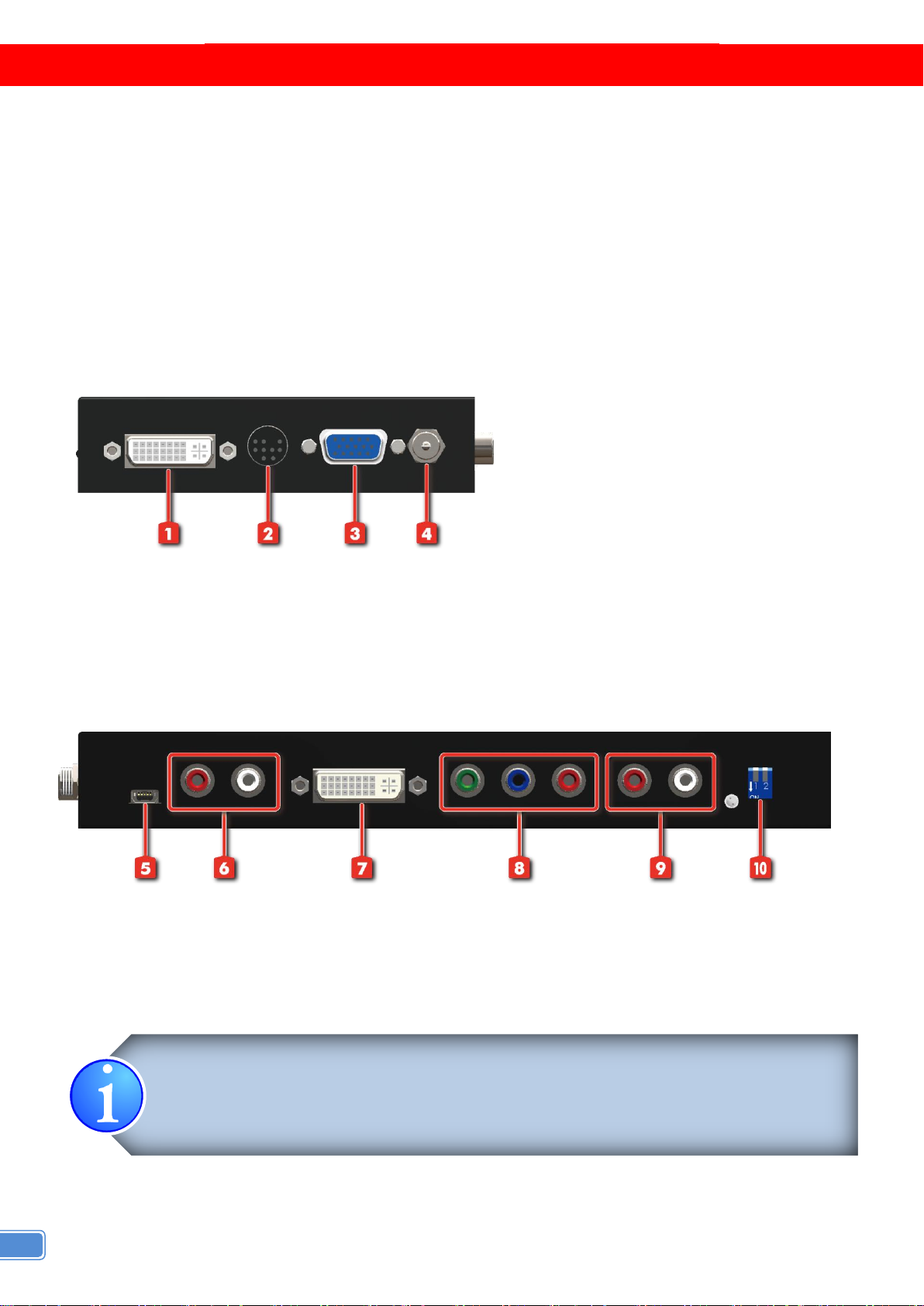
2. Connect a monitor, a projector or other displays that comes with DVI and/or VGA inputs by using 1
male-to-male DVI (VGA) cable to MX-2000A DVI output (you can connect 2 displays equipped with
DVI and VGA respectively by a DVI to DVI/VGA breakout cable (DDVY01)) .
3. Plug in DVI to DVI/VGAbreakout cable (DDVY01) to DVI-IN and plug in VGA to component breakout
cable (VYPBA01) to the VGA connector of the breakout cable.
4. Connect a device equipped with DVI output (such as PC) to the DVI connector of the breakout cable.
5. Connect a device equipped with component video output (YPbPr such as DVD player or camera) to
the 3-RCA jack of the VYPBA01.
6. Connect a device equipped with VGA output (such as laptop) to the VGA connector of the
MX-2000A.
7. Connect a device equipped with composite video output to composite input of the MX-2000A.
8. Connect your computer with the MX-2000A by a Mini USB cable and then install the software.
9. Plug in power adapter cable into 5V DC power jack.
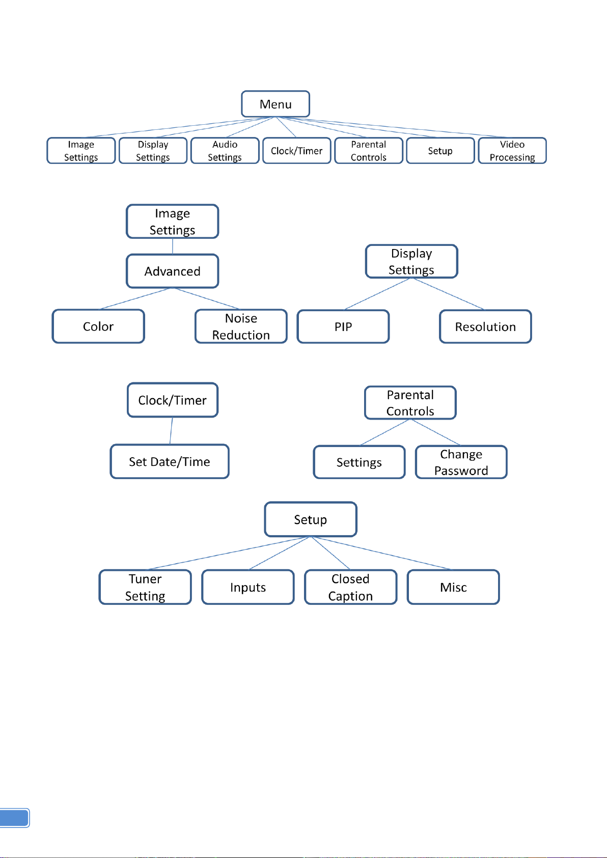
10.Switch on all devices connected and then switch on the video processor and then press “menu” to
display OSD menu.
11.Press down arrow key dropping down sub-menu to select the first channel (Main Channel)
video/graphic source.
12.Once the Main Channel has a video selected, press “exit” key to exit the sub-menu, and then move
right to the next item of OSD menu, which allows you to select the second channel (Sub Channel).
13.For detailed IR remote control operation, please refer to the On Screen Display menu and IR
operating instruction.

7
IR Remote Control
The MX-2000A is now shipped with a compact remote control that allows for direct access to most
commands used to control the video processor.
(1)
Mute
Mute the audio output
(2)
Power
Power on/off the device
(3)
Pip
Change to PIP Display mode
(4)
Scan
Enter Auto TV Tuner Mode while the input is TV
(5)
Split
Change to PAP Display mode
(6)
Pip Asp
PIP DisplayAspect Ratio Adjustment
(7)
Pip Source
Press to select a source for PIP channel
(8)
Pip Size
Press to change PIP channel size
(9)
Pip Pos
Press to change PIP channel position on Display
(10)
0-9
Number input
(11)
Vol+
Increase audio volume
(12)
Vol-
Decrease audio volume
(13)
Ch+
Increase TV channel number
(14)
Ch-
Decrease TV channel number
(15)
Jump
Switch back and forth between the two recently TV channels
(16)
Reset
Factory Reset
(17)
Freeze
Freeze output display
(18)
Sleep
Enter sleep mode
(19)
Left/Right/
UP/Down
Direction Control keys
(20)
Enter
Confirm Button
(21)
Menu
Display OSD menu
(22)
Exit
Move back to previous option or exit OSD menu
(23)
Source
Press to select a source for main channel
(24)
Info
Show the timer and input channel name
(25)
HDMI
HDMI Switch **
(26)
CC
Show close caption if embedded
(27)
Mode
Reserved
(28)
Auto
Auto adjustment when VGA is selected
(29)
Aspect
Display Aspect Ratio Adjustment
(30)
TV
Hot key to select TV input
(31)
CV1
Hot key to select composite input 1
(32)
CV2
Hot key to select composite input 2
(33)
YUV1
Hot key to select component input 1
(34)
YUV2
Hot key to select component input 2
(35)
SV1
Hot key to select S-Video input 1
(36)
SV2
Hot key to select S-Video input 2
(37)
VGA
Hot key to select VGA input
(38)
DVI
Hot key to select DVI/HDMI input
(39)
F1
Function Key 1
(40)
F2
Function Key 2
(41)
F3
Function Key 3
TABLE 2: IR FUNCTIONALITIES

8
On Screen Display Menu
Image Settings
Scheme: Normal, Vivid, Cinema, Game, Sport
Five slider controls for video quality: Brightness, Contrast, Saturation, Hue, Sharpness
Advanced: Noise Reduction, Flash tone, Dynamic Contrast, Color
Noise Reduction: MPEG NR (MPEG Noise Reduction) Temporal NR (Temporal Noise Reduction)
Flash tone: Enhance Flash
Dynamic Contrast: 5 Level Controls
Color: User Defined Color Temperature

9
Display Settings
Auto Aspect Ratio
Aspect Ratio: 16:9, Letter Box, Pillow Box Expand
Resolution: Define the output’s resolution
800x600@60, 1024x768@60, 1280x1024@60, 1280x720@60, 1366x768@60, 1440x900@60,
1400x1050@60, 1920x1080@60, 1920x1200@60, 1600x1200@60
PIP: PIP Mode: off, Large PIP, Small PIP, Side by Side (PBP)
PIP Position: Bottom-Right, Bottom-Left, Top-Left, Top-Right
Multi-PIP Configuration: POP7, 3x3 GRID, POP3, POP12
Multi-PIP On*: YES, NO
Pip Blend: Slider Control on the level of blending Main & Sub Channels
Audio Settings
Three Slider Control of Audio: Bass, Treble, Balance
Auto Volume*: On, Off
Sound Mode: Stereo, Mono, and SAP
Line Out: Fixed Volume*: Fixed Volume, Variable Volume
Speakers: On, Off
SPDFI Out*: On, Off
Clock / Timer
Sleep Timer: On, Off
Wake Alarm: On, Off
Set Date/Time: To setup the date and time
Parental Controls
Password: Default 1111
Setup
Inputs: Name each input.
Closed Caption: Embedded CC decoder for various formats.
Misc: OSD language, Factory Reset
Video Processing
Noise Reduction, Video Processing

10
OPERATION SOFTWARE
System Requirement and Precautions
1. The MX-2000A provides a software control program which runs under Microsoft Windows 98, 2000,
XP through the interface of USB interface.
2. Before you click on the icon of the software, make sure you have secured the connection between
your computer COM port and the MX-2000A, also switched on the MX-2000A with green LED light.
3. The MX-2000A has remote control and software control. To make sure all information shown in the
software is synchronized with those in the device, please click “Connect” to acquire the latest data
from the MX-2000A after you press any key on the remote control.
Instruction of Software Connection
1. Power up the MX-2000A and you can see both red and green LEDs on the front panel blink. Make
sure the serial port USB connection secure.
2. The first step after running the software is to automatically detect if the device responses correctly
through USB port. The process takes 15-20 seconds. If the response is not accurate, a warning
window will show up as the figure below.
The possible reasons causing this failure could be:
●The MX-2000A is not supplied with power or the MX-2000A enters deep sleep state. Please
check the current status, and reboot the MX-2000A.
●The serial connection through USB is not well established or some other software has
taken the available serial ports. Please make sure the USB cable is well connected and the
available serial port is free to be used by the MX-2000A.
●Com setting is not correct. Please make sure that from Menu→ Connector→ Setting.

11
3. If the serial connection is well established, you can see similar work window as below.

12
Instruction of Software Operation
Menu
File
a. Device Linkage: This will
synchronize the status or the
MX-2000A with the software,
especially after IR commands sent.
b. Data Table: It will show a dialog that
will list the input and resolution data.
c. Factory Reset: This will restore all
the system values back to the factory
default.
Connector
d. Setting: It will show a dialog, you
could modify serial port setting from
there.
e. Monitor: It will show a dialog that will
display the send and receive values.
Advance
f. Firmware Update: It will show a
dialog, that that for update the
firmware to the newest version.
g. Resolution Parameter: It will show a
dialog that for custom output
resolution.

13
Tree List Dialog
a. Output Resolution and Type
b. Layout Mode
c. Select audio source is from RL or HDMI
d. Main channel’s size and position Information
e. Sub channel’s size and position information
a. Main channel’s input signal select and information.
b. Sub channel’s input signal select and information.
c. “Input Info.” Button: Update the current signal
status.
d. “SWAP” Button: Switch the input signal between
the main and sub channel.
e. “Color Balance” Button: Auto adjust the AD gain
value.
f. “Configure” Button: For configure VGA input signal.
Flash Group: There are having 5 groups of custom
PAP Mode Layout in the device
HDD Group: This is saved in Pc.
f. The border control
g. Size and Position
h. Width
i. Color

14
Dialog
1. PAP control dialog:
While you move the mouse’s cursor near the borders, in
either red or blue, the icon of the cursor will change as
the figure below.
2. Data dialog:
About output resolution and input signal data. The
information is only for software development.
3. Serial port dialog:
Please select the correct number of serial port.

15
4. Firmware Update dialog:
It supports to update the firmware to the newest
version.
5. Resolution Parameter dialog:
It can edit and save the parameter of output resolution
in device.And it also can save the parameters in PC.
6. Serial Port Monitor
Monitor the send and receive data with serial port.

16
TROUBLESHOOTING
Problem
Recommendations
No power
Check if you are using 5V DC adapter and it is firmly plugged into the
MX-2000A
If you are recovering from power outage, accidentally unplug the adapter
or other power surge conditions, leave the device off for a while and then
power it on again.
No/ Erratic video
Make sure all cables are in good working condition and properly
connected to the MX-2000Aand displays.
Configure the output video resolution so that it doesn’t excess the native
resolution of the display. ( in this case, the message of “out of range” is
usually showed on your screen)
Make sure a video source is selected to the main channel. (press “Menu”
and check if the first item has a video source selected or press “Source”
to select a video source for the main channel)
Poor quality
We suggest that don’t use T-connectors to split your video source into to
images displayed on two different screens. That will lower output video
quality. Use a distribution amplifier instead of T-connectors.
Make sure the video source is not compressed and maintains the highest
native resolution.
Image position shifted
Press “Auto” key on the remote control.
Wrong color
Press “Color” key for auto color configuration.
Auto color configuration only works at VGA and component inputs.

17
LIMITED WARRANTY
The SELLER warrants the MX-2000A Dual-View Video Processor Audio Path to be free from
defects in the material and workmanship for 1 year from the date of purchase from the SELLER or an
authorized dealer. Should this product fail to be in good working order within 1 year warranty period, The
SELLER, at its option, repair or replace the unit, provided that the unit has not been subjected to accident,
disaster, abuse or any unauthorized modifications including static discharge and power surges.
Unit that fails under conditions other than those covered will be repaired at the current price of parts
and labor in effect at the time of repair. Such repairs are warranted for 90 days from the day of reshipment
to the BUYER. If the unit is delivered by mail, customers agree to insure the unit or assume the risk of loss
or damage in transit. Under no circumstances will a unit be accepted without a return authorization
number.
The warranty is in lieu of all other warranties expressed or implied, including without limitations, any
other implied warranty or fitness or merchantability for any particular purpose, all of which are expressly
disclaimed.
Proof of sale may be required in order to claim warranty. Customers outside Taiwan are responsible
for shipping charges to and from the SELLER. Cables are limited to a 30 day warranty and cable must be
free from any markings, scratches, and neatly coiled.
The content of this manual has been carefully checked and is believed to be accurate. However, The
SELLER assumes no responsibility for any inaccuracies that may be contained in this manual. The
SELLER will NOT be liable for direct, indirect, incidental, special, or consequential damages resulting
from any defect or omission in this manual, even if advised of the possibility of such damages. Also, the
technical information contained herein regarding the MX-2000A features and specifications is subject to
change without further notice.

18
APPENDIX –SUPPORTED RESOLUTION
[DVI-IN] socket
Supported Mode
Resolution
Supported Mode
Resolution
NTSC –480i / 525i
720x240 @60Hz
MAC
832x624 @75Hz
PAL–576i / 625i
720x288 @50Hz
VESA
1024x768 @60Hz
PAL–480p / 525p
720x483 @60Hz
MAC
1024x768 @60Hz
PAL–480p (16:9)
960x483 @60Hz
VESA
1024x768 @70Hz
PAL–576p / 625p
720x756 @50Hz
IBM
1024x768 @72Hz
HDTV –720p
1280x720 @50Hz
VESA
1024x768 @75Hz
HDTV –720p
1280x720 @60Hz
MAC
1024x768 @75Hz
HDTV –1080i
1920x540 @50Hz
VESA
1024x768 @85Hz
HDTV –1080i
1920x540 @60Hz
VESA
1152x864 @75Hz
HDTV - 1080p
1920x1080 @30Hz
MAC
1152x870 @75Hz
VESA
720x400 @85Hz
SUN
1152x900 @66Hz
VESA
640x350 @85Hz
SUN
1152x900 @76Hz
VESA
640x400 @85Hz
VESA
1280x960 @60Hz
IBM
720x400 @70Hz
VESA
1280x960 @85Hz
IBM
720x350 @70Hz
VESA
1280x1024 @60Hz
IBM
640x350 @70Hz
HP
1280x1024 @60Hz
IBM
640x400 @70Hz
IBM
1280x1024 @67Hz
VESA
640x480 @60Hz
HP
1280x1024 @72Hz
MAC
640x480 @67Hz
VESA
1280x1024 @75Hz
VESA
640x480 @72Hz
SUN
1280x1024 @76Hz
VESA
640x480 @75Hz
VESA
1600x1200 @60Hz
VESA
640x480 @85Hz
VESA
1920x1200 @60Hz
VESA
800x600 @56Hz
VESA
800x600 @60Hz
VESA
800x600 @72Hz
VESA
800x600 @75Hz
VESA
800x600 @85Hz
Table of contents
Other Gomax Media Converter manuals

Gomax
Gomax CV-503SZ User manual

Gomax
Gomax CV-305VS User manual

Gomax
Gomax CV-105 User manual

Gomax
Gomax SP-5002PZ User manual

Gomax
Gomax CV-C05S User manual

Gomax
Gomax MT-305A User manual

Gomax
Gomax MX-2003B User manual

Gomax
Gomax CV-53AK User manual

Gomax
Gomax CV-5005H User manual

Gomax
Gomax CV-305P User manual

Gomax
Gomax HUB-66U User manual

Gomax
Gomax CV-503ZK-A User manual

Gomax
Gomax CV-53BI User manual

Gomax
Gomax VW-1404ZH User manual

Gomax
Gomax MX-1003A User manual

Gomax
Gomax SP-5002VZC User manual

Gomax
Gomax VW-1404ZH-C User manual

Gomax
Gomax CV-915 User manual

Gomax
Gomax CV-503ZKM User manual

Gomax
Gomax VW-1404CZ User manual