Cimel CE318-N User manual

Multiband photometer CE318-N
User’s Manual (rev. Apr. 2015)
Firmware version 5.0 and above

CE318 Photometer
User's Operation Manual
Revision 5.0 April 2015 2/70
Dear Customer and users,
You have just purchased a Cimel sunphotometer and we would like to thank you.
We have placed in this instrument all our passion and know-how so that it best meets
your needs. Innovation and performance: we designed it so that it is always easy to
use.
In the line of Cimel products, you will also find a wide range of remote sensing and
automatic Sun Sky Photometer CE318-N that can be coordinated with your new
Cimel CE372 LIDAR.
Of course, in an ongoing effort to satisfy your demands as best as possible
concerning our products, our after-sales service department is at your disposal and
ready to listen and answer to all your questions and suggestions (contact information
at the end of this booklet).
Please visit our website at www.cimel.fr: you will find all our products, as well as
additional and useful information.
Cimel
As part of our commitment to constantly improve our products, we reserve the right to
make changes to their technical, functional and/or esthetic properties in line with their
technological development.
Caution: Before installing and using your instrument, please read carefully this
guide, which will help you to be quickly familiarized yourself with its operation.

CE318 Photometer
User's Operation Manual
Revision 5.0 April 2015 3/70
Table of Contents
1Product overview..........................................................................................................................4
1.1. Presentation ............................................................................................................................................... 4
1.2. System components quick description ........................................................................................... 4
1.3. Sensor head types ..................................................................................................................................10
1.4. Data transmission..................................................................................................................................11
2Installation ................................................................................................................................... 12
2.1. Installation site recommendations.................................................................................................12
2.2. Hardware installation and setup.....................................................................................................12
2.2.1. eeded tools......................................................................................................................................12
2.2.2. Tripod mounting..............................................................................................................................12
2.2.3. Case mounting ..................................................................................................................................14
2.2.4. Robot and sensor head mounting.............................................................................................15
2.3. Communication protocol installation and configuration ......................................................23
2.3.1. RS232 communication ..................................................................................................................23
2.3.2. Satellite transmission installation and configuration ......................................................25
3CU navigation menu ..................................................................................................................31
3.1. Basic Display ............................................................................................................................................31
3.2. PW menu....................................................................................................................................................31
3.3. SC menu ..................................................................................................................................................34
3.4. VIEW menu...............................................................................................................................................34
3.5. Man menu..................................................................................................................................................35
4Description of the scenarios measurements proceedings.......................................... 36
4.1. Scenario description and sequencing............................................................................................36
4.2. Group of measurement scenarios ...................................................................................................42
4.3. Measurement schedule in Auto mode ...........................................................................................43
4.3.1. Standard and polarized.................................................................................................................43
4.3.2. BRDF and BRDF 12 filters............................................................................................................44
4.4. Customized scenario programming ...............................................................................................45
ASTPWin software..................................................................................................................... 46
5.1. General........................................................................................................................................................46
5.2. Tools ............................................................................................................................................................48
5.3. Configuration menu ..............................................................................................................................49
5.4. Processing .................................................................................................................................................51
6Maintenance / Troubleshooting / FAQ .............................................................................. 2
6.1. Preventive maintenance......................................................................................................................52
6.2. Corrective maintenance ......................................................................................................................53
6.2.1. Solar panel and wet sensor replacement ..............................................................................53
6.2.2. Robot leveling adjustment...........................................................................................................54
6.3. Troubleshooting .....................................................................................................................................55
6.3.1. Communication and data transfer is down ..........................................................................55
6.3.2. Bad sun tracking ..............................................................................................................................56
6.3.3. InGaAs / silicon and A / K discrepancy..................................................................................58
6.3.4. High dark current............................................................................................................................58
6.3.5. Constant humidity...........................................................................................................................59
6.3.6. Robot errors ......................................................................................................................................60
6.3.7. Dissymmetric Almucantar...........................................................................................................61
6.3.8. Battery low.........................................................................................................................................61
7Technical specifications ..........................................................................................................62
7.1. General........................................................................................................................................................62
7.2.
Dimensional drawings .........................................................................................................................63
8After-Sales Service and Customer Relations ......................................................70

CE318 Photometer
User's Operation Manual
Revision 5.0 April 2015 4/70
1 Product overview
1.1.Presentation
This high-precision multiband photometer measures the optical properties of the
atmosphere especially by measuring on one hand, the sun irradiance and on the
other hand the soil and sky radiance. It provides the quantification and physical-
optical characterizations of the aerosols.
Due to its very low power consumption thanks to the MicroAmps
®
technology, to its
self-powered system and to its rugged design, the CE318 fully meets the operational
requirements of continuous monitoring in terms of reliability, long lifetime and very
low maintenance cost.
The CE318 photometer technology is constantly enhanced to match the new
technological challenges for climate observation and monitoring. Cimel’s
photometers are still the benchmark devices for most aerosol observing networks
and more specifically for the international federation of AERONET.
The large range of parameters that are derived and calculated from the
measurements and from the atmospheric physics equations make the CE318
photometer a worldwide benchmark device for the following applications:
•Characterization and quantification of aerosols
•Satellite calibration of aerosol measurements
•Detection of volcanic ashes plumes in real time
•Determination of Aerosol Optical Depth (AOD)
•Determination of fine mode and coarse mode AODs
•Determination of the optical properties of the atmosphere for satellite imaging
•Determination of the ocean's colour
•Determination of the amount of precipitable water vapor
•Air quality monitoring
•Volume size distribution
•Nature of aerosols
1.2.
System components quick description
The photometer system is delivered with:
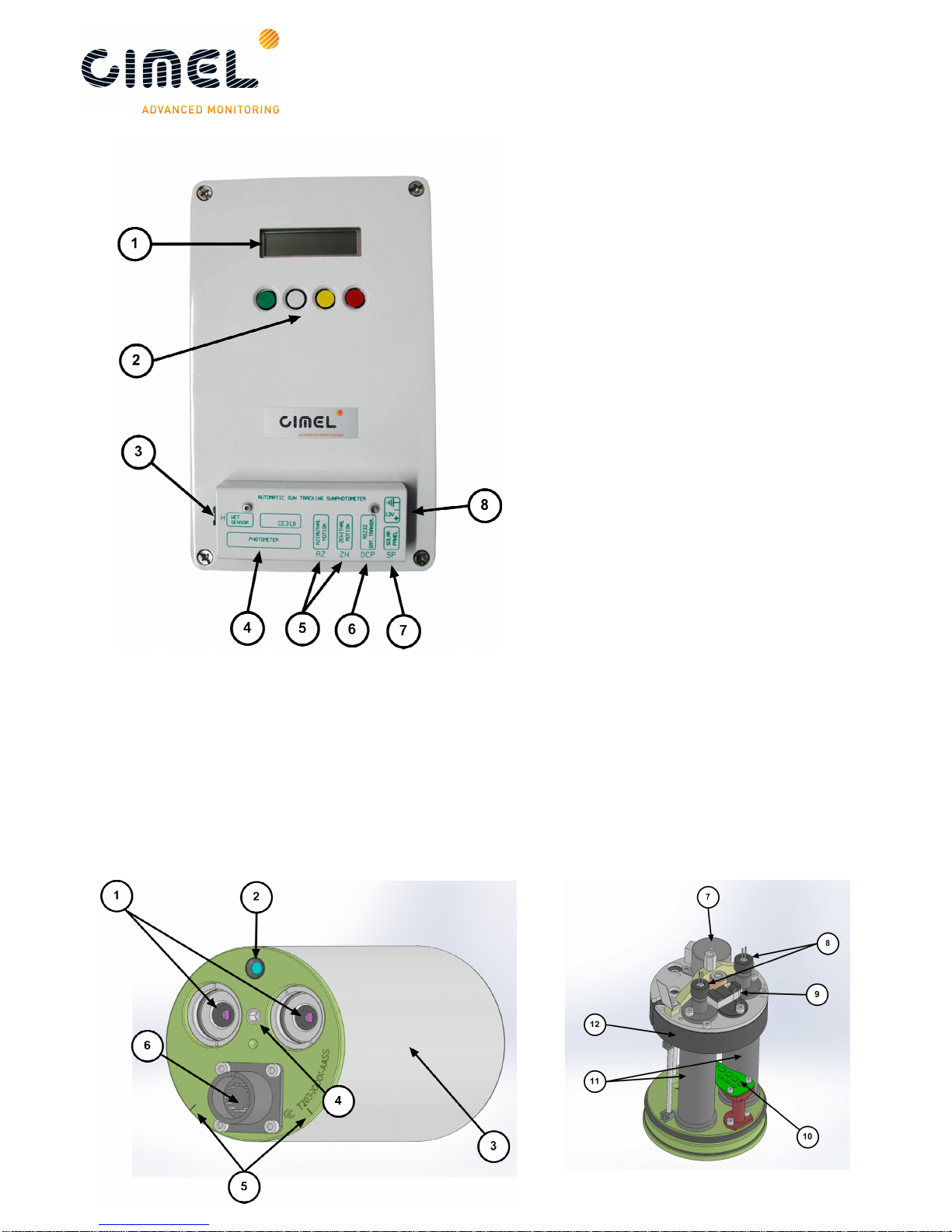
1. Control Unit (CU)
The Control Unit is the component where all the data acquired by the optical head
are sent and it is used as the user interface to parameterize the whole system
running.
The CU gets four colored buttons and a screen display which enable the users to
navigate through the menus.
The features and the menus are described more precisely in chapter 3.
CE318 Photometer
User's Operation Manual
Revision 5.0 April 2015 5/70
User interface:
1: Graphic display.
2: Coloured buttons.
Removable terminal block:
3: Wet sensor.
4: Sensor head.
5: Robot azimuth and zenith
motion.
6: DCP / Serial communication.
7: Solar panel.
8: External battery.
2. Sensor head and collimator
a. The sensor head
The sensor head measures the received signal from the sun, sky, soil or sea. Then it
is sent and recorded to the CU.
Detectors can be either silicon and InGaAs or silicon only for the SEAPRISM sensor
head type. InGaAs detector is used for near-infrared wavelengths.

CE318 Photometer
User's Operation Manual
Revision 5.0 April 2015 6/70
1: Front plate lenses and optical chambers entrance 7: Step by step motor
2: 4 quadrant detector lens 8: Detectors
3: Cover 9: Filter wheel detector
4: Threaded hole for collimator 10: 4 quadrant
5: Positioning notches 11: Optical chambers
6: Head sensor cord connector 12: Filter wheel carter
b. Collimator
The collimator is a component that enables the light to be guided correctly to the
sensor head outside lenses. The collimator helps to reduce the stray light.
1: notch 2: tightening screw 3: alignment hole 4: spot
3. Robot
The robot is the component on which the sensor head is attached. Its mechanical
design enables it to point on whole directions of the sky on the azimuthal and zenithal
angles with a very high accuracy.
It is controlled through 2 cables (with RJ11 connectors), one for each axis.
1: Adjustment wheel (X2)
2: Robot base
3: Strap
4: V-shaped part
5: Spirit level
CE318 Photometer
User's Operation Manual
Revision 5.0 April 2015 7/70
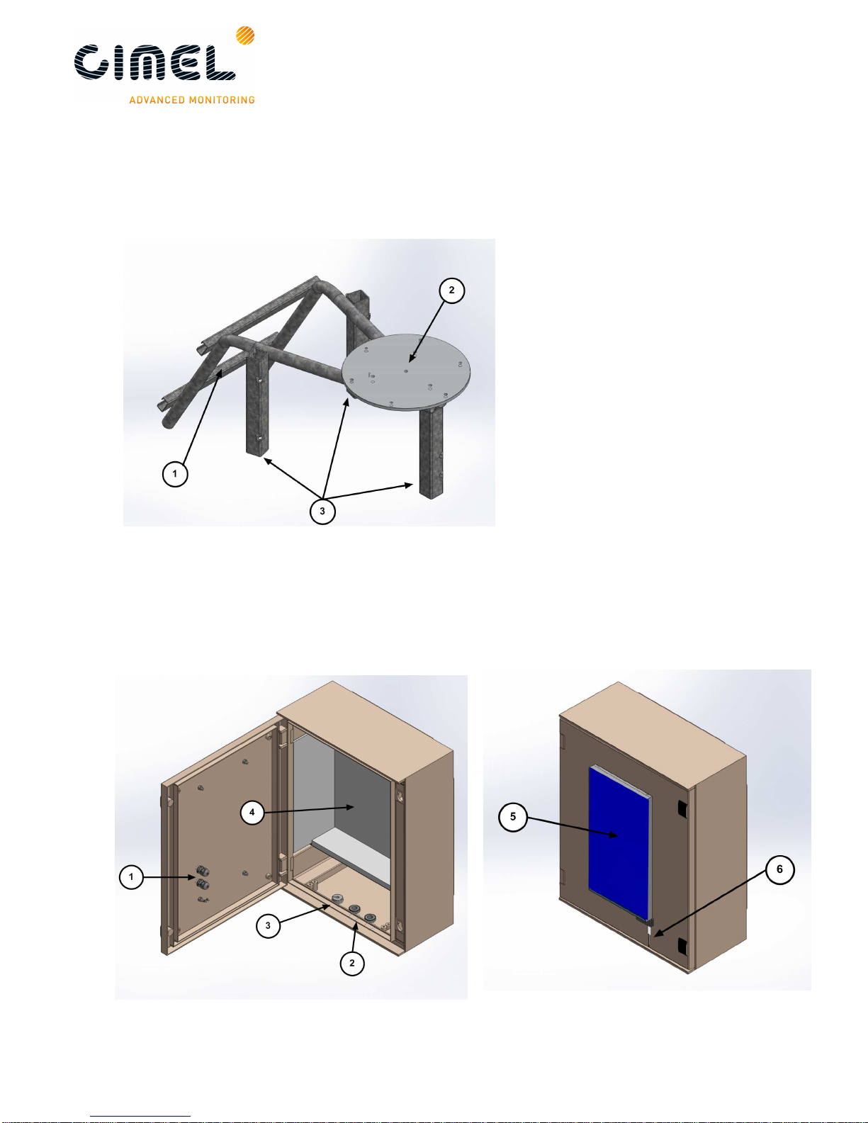
4. Tripod and tray
The tripod is the supplied infrastructure where the protection case and the robot are
fixed and that enables the whole system to be stably fixed on the ground.
The tray is a part fixed horizontally on the tripod and where the robot will be fixed on.
1: Emplacement for the
protection case
2: Tray
3: Tripod feet
5. Protection case with solar panel
The pair of batteries and the CU are placed into the case. The solar panel that
powers the system is incorporated in the case.
The output plug of the solar panel is a RJ11 connector.
CE318 Photometer
User's Operation Manual
Revision 5.0 April 2015 8/70
1: Cable gland. The wet sensor and solar panel wires will go through.
2: Cable gland. The robot and computer wires will go through
3: Cap. The sensor head cord will go through
4: Foam
5: Solar Panel
6: Wet sensor
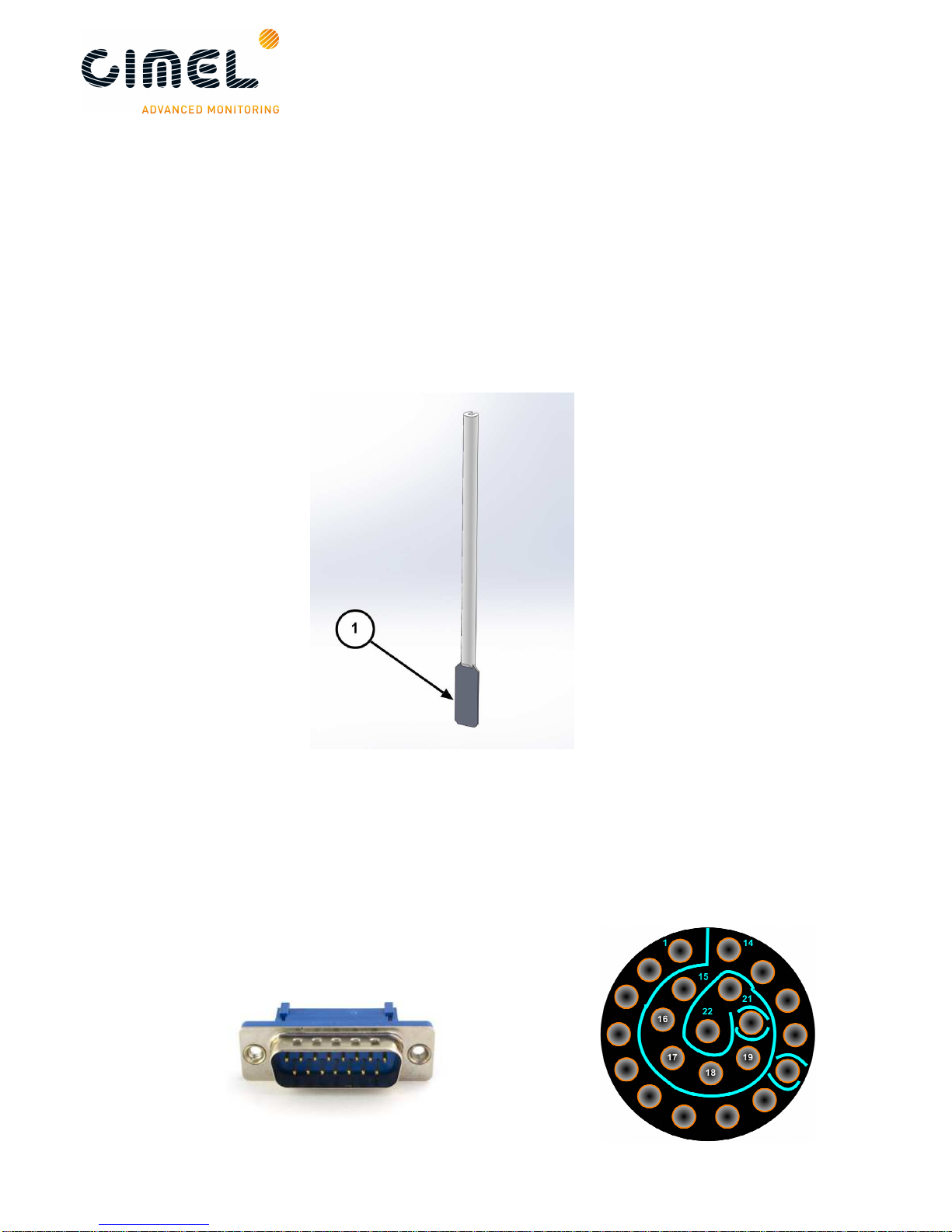
6. Wet sensor
The wet sensor detects rain in order to stop measurements and protect the sensor
head from water when it is raining. The output plug of the sensor is a RJ11
connector. Standard length of the wire is 3m.
7. Sensor head cord
The sensor head cord connects the CU and the sensor head. The standard length is
3 meters. One side connector is DB25 (male) type and this other side is Jupiter type
with 22 pins (female)

CE318 Photometer
User's Operation Manual
Revision 5.0 April 2015 9/70
8. Batteries and battery charger
The black batteries supply power to the CU. The battery is 8AH.
The YUASA battery is furnished when the satellite transmitter is used. The battery is
24AH.
The battery charger is used only in case of solar panel breakdown.
9. Flycase
10.Acquisition PC
The acquisition PC (not supplied) receives the data transmitted by the CU either via
RS232.
11.ASTPWin software
ASTPWin is the software used to communicate from the acquisition PC to the CU.
ASTPwin is not used when having a data transfer by satellite communication
protocol.

CE318 Photometer
User's Operation Manual
Revision 5.0 April 2015 10/70
12.Satellite transmitter (optional)
The satellite transmitter is useful in remote places where no reliable PC is available.
It enables to send the data directly to an appropriate geostationary satellite which has
a dedicated transmission channel for the CIMEL photometers.
1: Solar Panel Solartek
2: IAGI antenna
3: Mast
1.3.
Sensor head types
5 different sensor head types exist:
•Standard: It uses 340, 380, 440, 500, 675, 870, 937, 1020 and 1640 nm filters
•Polarized: A filter wheel containing 3 sets of 3 polarizers operating in infrared
(POL1), Ultraviolet (POL2), and visible (POL3) and which are orientated with a
120° angles is added on top of the wheel containing the Standard filters.
Additional information about the aerosols nature and shapes can then be
retrieved.
•Seaprism: It is designed for Ocean Color application. It uses only silicon
detectors. It uses 412, 440, 500, 531, 550, 675, 870, 937, 1020 nm filters.
•BRDF: it uses 380, 440, 550, 675, 740, 870, 937, 1020 and 1640 nm filters
•BRDF 12 filters: It is designed for satellite calibration. It uses 412, 440, 500,
555, 675, 702, 740, 782, 870, 937, 1020, 1640 nm filters.
The sensor head types differs in the presence of an additional wheel filter containing
polarisers for the Polarized type, the filters wavelengths mounted in the head sensor,
the and the scenario sequence established.
Filters wavelengths are defined in the UV-visible-IR spectrum according to scientific
retrieval purposes.
The filters and polarizers curves are delivered with the photometer.

CE318 Photometer
User's Operation Manual
Revision 5.0 April 2015 11/70
1.4.
Data transmission
The photometer can use 2 different communication protocols to send its data from
the CU.
•PC data transfer using a RS232 link to an acquisition PC. (default data
transmission)
•Satellite data transfer using a DCP transmitter module. The proper way to set
the module is explained in the Installation chapter.
Figure
3
: STANDARD option
Figure
1
: BRDF
option
Figure
5
: BRDF 12 filters option
Figure
4
: POLARISED option
Figure
2
: SEAPRISM option

CE318 Photometer
User's Operation Manual
Revision 5.0 April 2015 12/70
2 Installation
2.1.
Installation site recommendations
The site should be chosen carefully in order to comply with the following conditions:
•Easy access to facilitate the weekly maintenance of the device.
•The device should be installed in a clear area where it has the largest field of
view as possible so that it can track the sun from sunrise to sunset (no
buildings, trees…).
•Less than 100m cable length to a PC (RS232 link mode).
•A support where it can be strongly fixed so that the system is stable
(preferably the tripod).
2.2.
Hardware installation and setup
In this description, notions on how to manually control the photometer via the CU are
necessary, it is recommended to read chapter 3 and 4 to have a better overview of
what is done when installing the system.
However the following instructions are detailed enough so that it is not mandatory to
read the 2 chapters cited above.
If the tripod system is not used, skip to part 2.2.4.
2.2.1. Needed tools
To install the system, the following tools are needed:
•Open-end wrench size 10.
•Open wrench size 13.
If possible, a tubular spirit level will be used in addition of the robot spirit level to
make the installation easier (0.4mm/m accuracy).
2.2.2. Tripod mounting
The tripod mounting system is designed for easy installation of the photometers in
most site conditions.
1. Insert the three photometer tripod feet into the metallic frame.
2. Tight the 3 screws on the tripod feet.
3. Insert the ribs into the slides designed for this.
4. Insert the screw into the tray.
5. Tight strongly the screw into the rib with the tray in between.

CE318 Photometer
User's Operation Manual
Revision 5.0 April 2015 13/70
6. Attach the tripod feet to the ground with appropriate screws.
Note: Orientate the protection case emplacement South if the location is in the
Northern hemisphere or North if the location is in the Southern Hemisphere.

CE318 Photometer
User's Operation Manual
Revision 5.0 April 2015 14/70
2.2.3. Case mounting
7. Insert the 4 ribs into the metallic frame in order to fix the case.
8. Tight strongly the screw into the ribs with the inside of the case in
between.
9. Put the foam at the bottom of the case and on the sides, place the
batteries and the CU as shown on the picture below.

CE318 Photometer
User's Operation Manual
Revision 5.0 April 2015 15/70
2.2.4. Robot and sensor head mounting
10.Put the screws into white plastic part.
11. Put the screws on the holes trough the robot base but don’t tight them
to the end, let a 2 or 3 cm backlash so that the leveling that is done in
the next part is easier to do.
12.Connect AZ (robot AZimuthal motor), ZN (robot ZeNithal motor), solar
panel, wet sensor and battery wires to the removable terminal block of
the CU passing them going through the cable glands of the protection
case.

CE318 Photometer
User's Operation Manual
Revision 5.0 April 2015 16/70
13.Launch a Park scenario in the CU menu. The robot will find its zero
position.
14.Set the horizontal robot axis in the East-West direction by manually
turning the whole base of the robot.
15. Assemble the collimator to the sensor head front plates by tightening
the long central threaded rod. The notch must face the 4 quadrants lens
on the sensor head frontplate.

CE318 Photometer
User's Operation Manual
Revision 5.0 April 2015 17/70
Note: Watch out that the collimator and the sensor head are completely
interdependent. There should be no slack while trying to move the collimator after
having tightened it.
16.Strap the sensor head on the V-shaped support of the robot. Two
things are to be checked. First align the sensor head front plate with the
upper surface of the V-shaped support. Then use the notches present
both on the robot and the sensor head as a visual indicator to position
the sensor head correctly. Notches have to be aligned.
17.Plug the sensor head cord from the CU to the sensor head passing it
through the cap and attaching it to the pig tail. Connect the computer or
the transmitter to the DCP input on the removable terminal block via a
RS232 to RJ11 cable.
Note: A sufficient slack has to be maintained so that the head sensor cord will not be
too much extended while the device is operating, which can lead to the
malfunctioning of the photometer.

CE318 Photometer
User's Operation Manual
Revision 5.0 April 2015 18/70
18.Level the robot up so that it’s perfectly horizontal by playing on both
precision wheels until the spirit level on the top of the robot is centered.
This part is a little tricky and may take few trials. Using an additional
tubular sprit level may facilitate this step.

CE318 Photometer
User's Operation Manual
Revision 5.0 April 2015 19/70
19.Setting the date and the time UT in the AU menu
Important note 1: the time set is UT. If you are not sure about it, please visit this
website to get it:
http://fr.thetimenow.com/utc/universal_coordinated_time
Important note 2: seconds can not be set, wait until a whole minute is coming and
validate the time at this point more or less 2 seconds. For instance, validate the time
when it’s 14:05:00 or 17:18:00.
20.Set the GPS coordinates in the CU menu
Important note: the coordinates are entered in hours, minutes and seconds.
Therefore you may have to convert your GPS position if not into the good units.
This conversion can be done in ASTPWin software. Refer to part 5.

CE318 Photometer
User's Operation Manual
Revision 5.0 April 2015 20/70
21.Launch a Park scenario in the CU menu. The photometer head will find
its PARK position which is the nadir on the zenithal angle (head
orientated down).
If the head is pointing to zenith (orientated up), unstrap the sensor
head, reposition it in the opposite sense in the straps and do step 13
again.
Note: Place the spirit level on the robot V-shaped part after the PARK scenario. It
should be perfectly horizontal, if not refer to part 5.2.2.
22.Launch a GoSun scenario in the CU menu. The optical head is going to
point the sun.
After a GOSUN scenario the sun spot may not be centered on the target.
Table of contents
Other Cimel Measuring Instrument manuals


Popular Measuring Instrument manuals by other brands


iZ Technology
iZ Technology RADAR I Upgrade manual

Phenix Technologies
Phenix Technologies KVM100 manual

Horstmann
Horstmann ComPass B Instructions for use

Minebea
Minebea CSD-903-73 instruction manual

Direct Scientific
Direct Scientific DSM-502 Operation & maintenance manual

DeFelsko
DeFelsko PosiTector 200 instruction manual