CIMLINE M Series User manual

Sealant Melter Applicator Machine
Owner/Operator Manual
CIMLINE.COM
2601 Niagara Lane · Plymouth, MN 55447 · (763) 557-1982 · (877) 841-0848 · Fax (763) 557-1971
Part # 161698 Rev G 6/07/21
M4
DUAL
M4
M1
M2

In addition to this operators manual, a packet containing IMPORTANT INFORMATION has been
enclosed with your CIMLINE M-Series Melter.
The following Manufacturer's Documents are included for the following parts:
a) Engine
b) Material Pump
c) Burner
TABLE OF CONTENTS:
Serial Number, Model Number, Engine Number .....................................3
Contacting Cimline ..............................................................................3
Personal Safety, Signal Words in Manual ..............................................4
Trailer Safety......................................................................................5
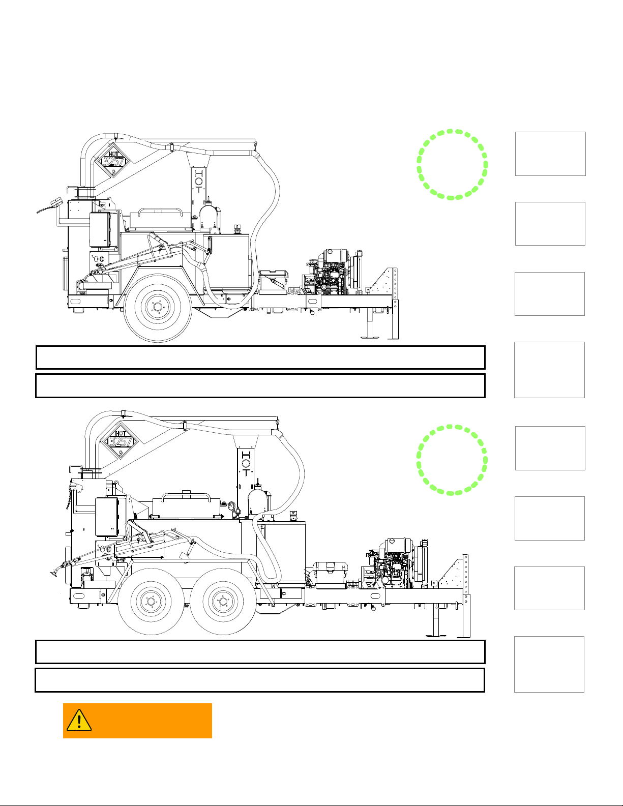
M-Series Weight and Dimensions .........................................................6-7
Replacement Labels ............................................................................8
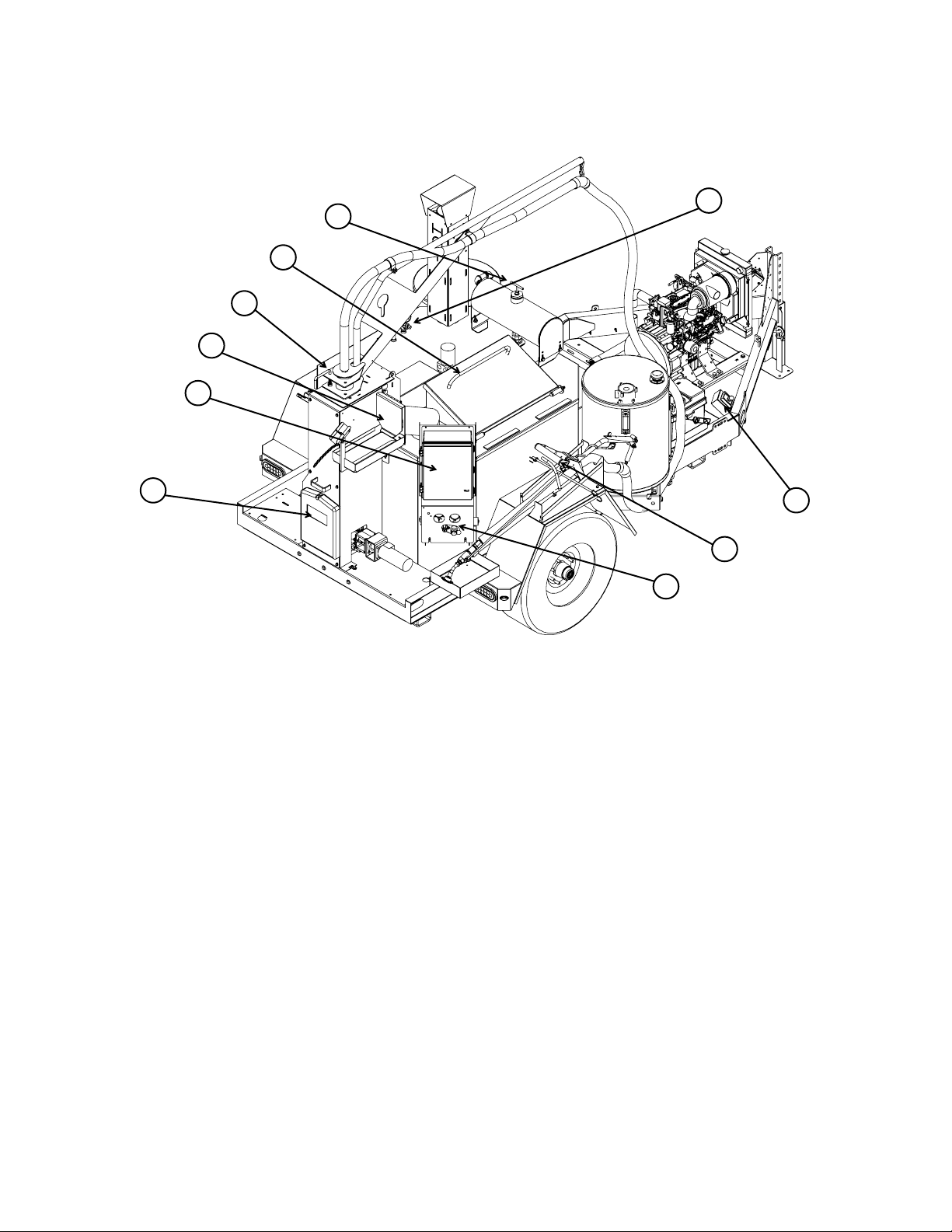
M-Series Feature Overview..................................................................9
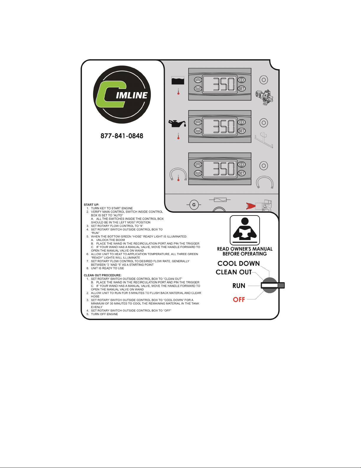
M-Series Control Panels and Their Functions ........................................10-11
M-Series Manual Sub Control Panel and its Functions ...........................12-13
M-Series Start Up Procedure ...............................................................14-15
M-Series Clean Out/Shut Down Procedure ............................................16-17
M-Series Sealant Material Tank Capacity ..............................................18
M-Series Automatic Temperature Control Setting ..................................19
M-Series Fluid and Components Specifications .....................................20
M-Series Heat Transfer Oil Specs ........................................................21
MAINTENANCE AND TROUBLESHOOTING:
M-Series Maintenance Schedule.............................................................................23
M-Series Maintenance - Changing Heat Transfer Oil..............................................24
M-Series Maintenance - Sealant Material Pump .....................................................25
M-Series Maintenance - Sealant Material Plumbing................................................26
M-Series Maintenance - Recirculation Valve Timing ...............................................27
M-Series Maintenance - Hydraulic Oil Servicing .....................................................28-29
M-Series Maintenance - Tank Burner......................................................................30-34
M-Series Maintenance - Trouble Shooting Guide....................................................35
M-Series Melter Applicator Service Parts Kits ........................................36-37
PARTS AND ASSEMBLY DIAGRAMS:
M-Series Trailer Wiring Diagram and Parts ...........................................39
M-Series Main Wiring Harness .............................................................40-41
M-Series Control Panel Wiring Diagram and Parts .................................42-45
M-Series Combustion Chamber Parts ...................................................46
M-Series Tank Burner Internal Wiring Diagram ......................................47
M-Series Tank Burner Parts .................................................................48
M-Series Hydraulic Reservoir and Diesel Tank Parts .............................49
M-Series Hydraulic Manifold Parts and Schematic .................................50-53
M-Series Diesel Engine Components ....................................................54-57
M-Series Sealant Material Plumbing Parts ............................................58-63
M-Series Sealant Wand Diagram and Parts ...........................................64-66
M-Series Agitation System Diagram and Parts ......................................67-68
M-Series Miscellaneous Components and Parts ....................................69-71
M-Series Optional Sealant Wand Attachments.......................................72
Shipping Papers and Information

3
Melter Serial Number:
_________________________________
Model Number:
_________________________________
Pump Number:
_________________________________
Engine Manufacturer:
_________________________________
Engine Model (H.P.):
_________________________________
IMPORTANT: This manual contains the basic information required to operate, maintain and
repair the CIMLINE Melter you have purchased. The use of this manual insures accurate
adjustments, operation, basic maintenance and proper lubrication of your equipment. Please keep a
copy with the machine at all times.
CONTACTING CIMLINE
At Cimline, impressing the customer is one of our core values. We want to make sure you are
covered for any general or technical questions you may have on your new CIMLINE equipment.
Please use the following information to get the support you need if this manual does not provide the
answers you are looking for.
Cimline Dealer Network:
Your local dealer is always your first point of contact when looking for parts, maintenance, technical
support, warranty information or answers to your questions. No one should know you and your
business better than your local dealer, and they should always be the first call you make when
looking for answers to your questions.
CIMLINE Local Dealer Name: CIMLINE Local Dealer Phone Number:
_________________________________ _________________________________
CIMLINE Sales:
Toll Free: (877) 841-0848 • Telephone: 763-694-2665 • Fax: 866-557-1971
Corporate Headquarters: 2601 Niagara Lane N, Plymouth, Minnesota 55447
www.cimline.com
Any parts orders or service problems relating to CIMLINE equipment
should be directed to your local dealer FIRST.
CIMLINE Customer Care and Technical Service:
CIMLINE Technical Service is available Monday - Friday during normal business hours.
Toll Free: (877) 841-0848 • Telephone: 763-694-2665 • Fax: 866-553-7765
CIMLINE Parts and Warranty Items:
Toll Free: (800) 328-3874 • Telephone: 763-694-2638 • Fax: 866-553-7765
www.cimline.com • Email: customercareorders@plymouthind.com

4
OPERATOR MUST READ AND UNDERSTAND ENTIRE
OPERATORS MANUAL BEFORE PROCEEDING.
THIS PAGE ONLY PROVIDES AN OVERVIEW OF SAFETY INFORMATION
Required clothing
includes:
Gloves with wristlets • Heavy leather boots or shoes • Face shield
• Long sleeve shirt with sleeves rolled down and cuffs buttoned
• Long pants with no cuffs
GENERAL OPERATION SAFETY:
Perform a DOT pre-trip inspection before towing. • Always use pin with swivel jack.
Never go under trailer with out first stabilizing trailer. • Never use a damaged swivel jack.
Never touch material expelled by melter while still hot. • Never stand on any part of the machine.
Do not operate without safety cover on hose. • Load melter from ground level.
Never leave machine unattended while it is running. • Do not touch exhaust stacks or mufflers.
Keep material door closed at all times except when adding material.
Personal Safety
The melter operates at elevated temperature which can cause
burns. Operator and anyone working in close proximity to hot
materials must always wear protective clothing.
WARNING
Signal Words in Manual:
The signal words DANGER, WARNING and CAUTION, are used to identify levels of hazard
seriousness.
NOTICE: Is used to address practices not related to personal
injury.
NOTICE
DANGER! Indicates a hazardous situation which, if not avoided,
will result in death or serious injury.
DANGER
WARNING! Indicates a hazardous situation which, if not avoided,
could result in death or serious injury.
WARNING
CAUTION! Indicates a hazardous situation which, if not avoided,
could result in minor or moderate injury.
CAUTION

5
GENERAL SAFETY CONSIDERATIONS:
Operating this machine requires workers to perform work behind the trailer, it is critical to perform the
work safely. Communication between the tow vehicle driver and worker is critical. Worker and tow
vehicle driver must stay in communication, use an audible device or visual signals to communicate. A
worker must never ride on the trailer or position him or herself between the tow vehicle and trailer
when the tow vehicle is running. Tow vehicle driver must always be aware of workers position.
Only use a tow vehicle that is equipped with an electronic brake control system and has the
appropriate towing capacity. The best means for determining the vehicle's towing capacity is to read
the vehicle owner's manual. The owner's manual will provide detailed instructions and limitations,
usually accompanied by tips for safe towing. If the owner's manual has been misplaced, most
manufacturers provide free downloadable copies on their website. Towing with an undersized tow
vehicle can cause the trailer to tow improperly, potentially causing loss of control. Overloading can
also cause unintended failures to tow vehicle.
The weight of your trailer listed in this manual is for the base model without any additional
accessories or the weight of the sealant material. The weight of your trailer will vary, weigh your
machine to determining your Gross Vehicle Weight (GVW). Scales are sometimes available to use at
state highway weigh stations, refuse transfer stations and commercial truck stops.
TRAILER STABILIZATION PROCEDURE:
Going under the trailer puts a person at risk of severe injury or
death. Follow the procedure below to stabilize trailer before going
under the trailer.
METHOD #1 HITCH TO VEHICLE:
Park both the tow vehicle and trailer on a flat level surface. Place tow vehicle in park and remove
keys.
METHOD #2 UNHITCHED:
Park trailer on a level surface. Place wheel blocks in front of and behind wheels on both sides of the
trailer. Inspect your swivel jack thoroughly for damage or abnormal wear, especially if it was subjected
to abnormal load or shock. [If damaged do not use, replace swivel jack.] Turn the swivel jack to the
vertical position and pin in place. Use the swivel jack to decouple trailer from tow vehicle. After
raising the hitch coupler, crib, block, or otherwise secure the trailer at once.
Trailer Safety
WARNING
BREATHING DIESEL ENGINE EXHAUST EXPOSES YOU TO CHEMICALS KNOWN TO THE
STATE OF CALIFORNIA TO CAUSE CANCER AND BIRTH DEFECTS OR OTHER REPRODUC-
TIVE HARM. ALWAYS START AND OPERATE THE ENGINE IN A WELL-VENTILATED AREA. IF
IN AN ENCLOSED AREA, VENT THE EXHAUST TO THE OUTSIDE. DO NOT MODIFY OR TAM-
PER WITH THE EXHAUST SYSTEM. DO NOT IDLE THE ENGINE EXCEPT AS NECESSARY.
FOR MORE INFORMATION GO TO; WWW.P65WARNINGS.CA.GOV/DIESEL.
WARNING

6
HEIGHT
92 INCHES
(234 cm)
WIDTH
82 INCHES
(208 cm)
LENGTH
148 INCHES
(376 cm)
BASE
WEIGHT
4200 Lbs.
(1814 kg)
WEIGHT AND DIMENSIONS ARE FOR BASE UNIT WITHOUT OPTIONS.
WEIGHT LISTED DOES NOT INCLUDE MATERIAL WEIGHT.
M-Series Weight and Dimensions
Product specification may change without notice.
Images contained in this manual may differ from the actual product.
M1
M2
To maintain safe operation of trailer while in transport,
do not fill tank more than 75% of total tank capacity.
Sealant Material Tank Size is 150 Gallons
Maximum Safe Operational Sealant Material Tank Capacity is 112 Gallons
HEIGHT
90 INCHES
(229 cm)
WIDTH
81 INCHES
(206 cm)
LENGTH
164 INCHES
(417 cm)
BASE
WEIGHT
4700 Lbs.
(2132 kg)
Sealant Material Tank Size is 230 Gallons
Maximum Safe Operational Sealant Material Tank Capacity is 172 Gallons
WARNING

7
M4
DUAL
M4
M-Series Weight and Dimensions
HEIGHT
84 INCHES
(213 cm)
WIDTH
87 INCHES
(221 cm)
LENGTH
189 INCHES
(480 cm)
M4 BASE
WEIGHT
6000 Lbs.
(2801 kg)
M4 DUAL BASE
WEIGHT
6500 Lbs.
(2994 kg)
Product specification may change without notice.
Images contained in this manual may differ from the actual product.
To maintain safe operation of trailer while in transport,
do not fill tank more than 75% of total tank capacity.
Sealant Material Tank Size is 410 Gallons
Maximum Safe Operational Sealant Material Tank Capacity is 307 Gallons
WEIGHT AND DIMENSIONS ARE FOR BASE UNIT WITHOUT OPTIONS.
WEIGHT LISTED DOES NOT INCLUDE MATERIAL WEIGHT.
WARNING

8
M-Series Replacement Labels
Inspect your labels and replace any that are damaged.
Contact your dealer to order replacement labels.
PN: 161808
PN: 161441

9
10
M-Series Feature Overview
NOTE: This general outline will familiarize you with this machine, dependent on model,
location and style and may vary with options installed. Read through the entire manual before
putting this machine into operation.
1) Main Control Panel: The main control panel is used to control the primary functions of the
melter, including simple automated user controls for Off / Run / Clean Out / Cool Down as well as
manual control of the sealant material pump direction and tank agitator. You can also monitor or
adjust the temperature of the sealant material and heat transfer oil on the control sub panel. See
page 10-11 for more information on the main control panel.
2) Boom Rotation Lock: This handle locks the boom from rotating during transport.
3) Loading Door: Place the sealant material block or biscuit on the open door to load the sealant
melting tank. See page 14 for more information on safely loading sealant material into the melter.
4) Heat Transfer Oil Level Dipstick: Allows you to monitor the amount of heat transfer oil in the
melter oil tank. See page 24 for more information on using the heat transfer oil dipstick.
5) Heat Transfer Oil Temperature Gauge: Displays the heat transfer oil temperature.
6) Ignition Switch: Engine key “Start”/ “On” / “Off” and also displays engine running hours, glow plug
status, alternator charge, engine oil pressure and engine coolant warnings.
7) Sealing Wand: Dispenses sealant material to the ground.
8) Material Sealant Flow Control: Controls the flow rate of sealant by varying the pump speed.
9) Recirculation Port: The sealing wand is placed here when not in use. This allows operator to
continue circulating sealant material through the hose and wand to prevent the sealant material from
cooling and freezing up.
10) Instruction Manual Case: Keeps the manual and important documentation protected.
1
9
2
3
4
8
7
6
5

10
MAIN CONTROL PANEL:
The Main Control Panel is used to operate the melter control system. Controls located on the outer
cover are for operating in AUTO mode only.
OFF: Shuts down power to the control panel and the pump, agitator and burner.
RUN: Allows the preprogrammed controllers to turn on the pump, agitator, and burner.
CLEAN OUT: Shuts down the burner and reverses pump flow direction to clean out material
from the hose and internal plumbing returning the sealant material to the material tank
COOL DOWN: - Shuts down the burner and pump and turns the agitator only. This allows the
material to cool down more consistently, extending the life of the material remaining in the tank.
Inside the Main Control Panel box is a Sub Control Panel.
See pages 12-13 for detailed explanation of its use.
M-Series Control Panels and Their Functions

11
M-Series Control Panels and Their Functions
DUAL PUMP AUXILIARY CONTROL PANEL (M4 DUAL ONLY):
The dual pump auxiliary control panel is used to operate the secondary pump and hose controls.
OFF: Shuts down power to the auxiliary control panel. Keep the auxiliary control panel in the
“OFF” position when not in use (center position on the switch).
AUTO: All controls will be operated from the main control panel.
MANUAL: Overrides material pump controls from the main control panel and allows the
secondary material pump to work independent of the main material pump.
SEAL: When operating in MANUAL mode this option will allow the material pump to flow
material forward to wand.
CLEAN OUT: When operating in MANUAL mode this option reverses pump flow direction to
clean out material from the secondary hose, wand and internal plumbing returning the sealant
material to the material tank.

12
M-Series Manual Sub Control Panel and Its Functions
1)
2)
3)
4)
5)
6)
7)
8)
9)
10)
11)
12)
14)
13)

13
M-Series Manual Sub Control Panel and Its Functions
1) MAIN CONTROL SWITCH:
Auto: (left position) Machine will operate from the systems preconfigured program using the
rotary switch control located on the outside front cover.
Off: (center position) Power to all systems will be off and burner, pump and agitator will stop.
Manual: (right position) Main rotary switch on front cover is no longer active. The three switches
below for temperature control, pump and agitator must be used to control the melter’s operations.
2) TEMPERATURE CONTROLLER ON / OFF SWITCH: When this switch is on, the three digital controllers
to the right will be energized and they will be controlling the diesel burner and activate the hydraulics for
agitator motor, sealant material pump and the heated hose.
3) MATERIAL PUMP SWITCH:
Seal (Forward): When the switch is on “SEAL (Forward)” the pump will be rotating counter clockwise
with sealant material recirculating back to sealant material tank or to the application wand.
Off: When the switch is “OFF”, the pump will not be rotating.
Clean-out (Reverse): When the switch is on “CLEAN-OUT”, the pump will be rotating clockwise in
reverse direction and will be drawing back any sealant material in the application wand and plumbing
system back to the sealant material tank.
4) AGITATOR CCW / OFF / CW SWITCH: This switch controls the rotation of the agitator from counter-
clockwise (CCW) or clockwise (CW). If the switch is in the center position, the agitator will not rotate.
5) SEALANT TEMPERATURE CONTROLLER: The control system on your CIMLINE melter has been
factory set to run the most common types of sealant materials. See page 19 to override or change
settings.
6) PUMP LIGHT (Green): This LED light indicates that the sealant material has reached the preset
temperature and if the unit is running in the auto mode, the hydraulic circuit for the sealant material pump
will be activated. If enough sealant material has melted the pump should be turning and sealant material
should be circulating through the system and back into the top of the sealant material tank.
7) HEAT TRANSFER OIL CONTROLLER: The control system on you CIMLINE melter has been factory
set to not exceed the OEM heat transfer oil limits for maximum temperature. It is advised to only use heat
transfer oil from CIMLINE. See Page 21 for heat transfer oil information and specifications.
8) AGITATOR READY LIGHT (Green): This LED light indicates that the heat transfer oil has reached
the preset temperature and if the unit is running in the auto mode, the hydraulic circuit for the agitator will
be activated. If enough sealant material has melted the agitator should be turning.
9) HOSE TEMPERATURE CONTROLLER: The control system on your CIMLINE melter has been factory
set to run a heated hose to the proper temperature for successful application of sealant material.
10) HOSE READY LIGHT (Green): This LED light indicates that the heated hose has reached the
preset temperature and is ready to use.
11) DIESEL BURNER LIGHT (Yellow): This LED light indicates that the material and heat transfer oil
temperature control are demanding that the diesel burner circuit is turned on.
12) HEATED HOSE FUSE: This is a 240V/18A slow-blow fuse for protecting the heated hose.
13) HEATED HOSE GENERATOR LIGHT (Yellow): This LED light indicates that the heated hose
temperature control is demanding that the generator circuit is turned on.
14) LOW FLOW SWITCH: Some sealants dispense best at low flow rates (<4 on the flow controller). If
the sealant material dispenses unevenly, switch the AUTO/MANUAL switch to MANUAL and place the
low flow switch on “FOR MATERIAL FLOW LOWER THAN 4”. This will make the sealant material pump
only rotate when the wand trigger is pressed, resulting in a smoother, more consistent flow.
CIMLINE recommends using the Main Control Panel in “AUTO”
control mode. “MANUAL” mode is provided for trouble shooting
and trained advanced/experienced users.
NOTICE

14
LOAD FRESH SEALANT MATERIAL INTO TANK:
All sealant material must be clean. Keep all foreign matter
out of melting tank to avoid damage to pump and systems.
1) Open the material door (A) and place the block of sealant
material (B) on the open door against the holder (C).
2) Push door to the closed position.
TO PREVENT CONTACT WITH
HOT SEALANT DO NOT DROP MATERIAL INTO THE MELTER
WITH EITHER OR BOTH DOORS OPEN.
LOADING OPERATOR MUST WEAR ALL PROTECTIVE
CLOTHING COVERED ON PAGE 4.
LOAD MATERIAL FROM GROUND ONLY. NEVER CLIMB ON
THE TRAILER TO LOAD.
M-Series Start Up Procedure
1. START ENGINE:
A) Turn key on engine control to “ 1”.
B) Allow 3-5 seconds to heat glow plugs. (Flashing green
light will turn to solid green)
C) Turn key to “ 2” and release when engine starts.
2. VERIFY SWITCHES ON CONTROL PANEL:
A) Verify main control switch inside control box is set
to “AUTO”.
B) Verify ALL the switches inside the control box are
in their left most position.
3. SET ROTARY FLOW CONTROL TO 9:
A) Set rotary switch (A) on the hydraulic block to “9” for maximum
sealant material flow during the start up process.
NOTE: Remember to return the flow control back to your start-
ing point setting before beginning sealant material application.
(B)
(C)
(A)
4. POWER UP CONTROL PANEL:
A) Set control panel rotary switch on front (outside)
of control box to the “RUN” position.
(A)
WARNING

15
Do not pull or kink the hose. Moving the hose prior to it being up
to operating temperature could permanently damage the hose.
7. SET WAND FLOW CONTROL SPEED:
A) Set flow control (A) to “0” with the wand securely in the recircula-
tion port, the trigger pinned (B) and the manual valve open (C).
B) Slowly adjust the flow control knob to begin the flow of material
through the wand. The flow of material can be observed through
the recirculation port.
C) Generally most sealant materials dispense at a setting between
“3” and “5” on the flow control.
D) Once the material is flowing at the desired rate pull the manual
valve handle back to close the valve on the wand.
M-Series Start Up Procedure
5. PREPARE HOSE AND WAND:
When the (green) hose ready light (A) is
illuminated.
A) Unlock the boom (B) by raising and
displacing the locking pin. The boom
is free to swing now.
B) Place the wand in the recirculation
port (C) and pin the trigger.
C) If your wand has a manual valve, move the handle forward to open the valve on the wand.
6. ALLOW UNIT TO HEAT SEALANT MATERIAL TO
CORRECT APPLICATION TEMPERATURE:
The unit should be ready for operation when all three (green) ready
lights are illuminated. The correct sealant material temperature is
now reached in the sealant material tank. The agitator and pump
should be running and the heated hose should be up to the proper
temperature.
(B) (C)
(B)
(C)
Use caution when in proximity of flowing
hot material. This includes proper face
and skin protection.
8. RUNNING SEALING WAND:
With the start up procedure complete you are ready to begin sealing.
A) Remove the pin from the wand trigger.
B) Remove the wand from the recirculation port.
C) Push the manual valve handle forward and squeeze the wand trigger to begin the flow and
start sealing.
D) Adjust the flow control as needed to best fit your movements and the size of the areas you
are sealing.
(A)
(A)
CAUTION
CAUTION

16
1. SET ROTARY SWITCH OUTSIDE CONTROL BOX TO “CLEAN OUT”:
The clean out function on the control box will reverse the sealant
material pump and begin to evacuate the wand, heated hose and
internal plumbing of a majority of the sealant material and return it
back to the sealant material tank. The entire procedure (steps A -
G) should be followed and all steps properly executed. Following
this process fully will increase start up efficiency on the next job. If
using duck-bill tip, remove from wand.
A) Place the wand in the recirculation port (A) and pin the
trigger (B).
B) If your wand has a manual valve, move the handle for-
ward to open the manual valve on the wand (C).
C) Set rotary switch (E) on the hydraulic block to “9” for maxi-
mum sealant material flow during the clean out process.
D) Allow the unit to run for 5 minutes to suck back as much of
the sealant material to the tank as possible.
E) After 5 minutes, unpin the wand trigger, pull the handle back
on the manual valve to close the valve and remove the
wand from the recirculation port.
F) Properly secure the wand in the storage tray (F).
G) Swing the boom all the way forward and lock the
boom using the locking pin (D).
M-Series Clean Out / Shut Down Procedure
2. SET ROTARY SWITCH OUTSIDE CONTROL BOX TO “COOL DOWN”:
The “Cool Down” function on the control box will shut down all func-
tions on the M-Series except the sealant material agitator. The cool
down step should be run for a minimum of 30 minutes. Following
this process will allow the sealant material to more evenly cool
down and increase longevity of the material remaining in the tank.
(B) (C) (D)
(A)
(E)
3. SET ROTARY SWITCH OUTSIDE
CONTROL BOX TO “OFF”
4. TURN OFF ENGINE
(F)
Caution should be taken
to not pull or kink the
hose excessively while
moving the boom back to its storage position.
Moving the hose when cold could permanently
damage the hose.
CAUTION

17
METHOD #1
1. SET AUXILIARY HOSE CONTROL PANEL SWITCH (A) TO “AUTO”:
The clean out function on the auxiliary hose will run concurrently with
the primary hose cleanout procedure on the main control box.
Follow all instruction for the auxiliary hose as you would on the primary
hose (as described on the previous page).
Make certain to set rotary switch (B) on the hydraulic block to “9” for
maximum sealant material flow during the clean out process.
The entire procedure (steps A - G) on the previous page should be fol-
lowed and all steps properly executed for the auxiliary hose. Following
this process fully will increase start up efficiency on the next job.
METHOD #2
1. SET AUXILIARY HOSE CONTROL PANEL SWITCH (A) TO “MANUAL”
2. SET THE MATERIAL PUMP SWITCH (B) TO “CLEAN OUT”:
The clean out function on the auxiliary hose will run independently of
the primary hose cleanout procedure on the main control box.
The entire procedure (steps A - G) should be followed and all steps
properly executed for the auxiliary hose. Following this process fully
will increase start up efficiency on the next job.
A) Place the auxiliary wand in the secondary recirculation port (C)
and pin the trigger (D).
B) If your wand has a manual valve, move the handle forward to
open the manual valve on the wand (E).
C) Set rotary switch (G) on the hydraulic block to “9” for maximum
sealant material flow during the clean out process.
D) Allow the unit to run for 5 minutes to evacuate as much of the
sealant material back to the tank as possible.
E) After 5 minutes, unpin the wand trigger, pull the handle back on
the manual valve to close the valve and remove the wand from
the recirculation port.
F) Properly secure the wand in the auxiliary storage tray.
G) Swing the boom all the way forward and lock the boom using
the locking pin (F).
M4 Dual Hose Clean Out / Shut Down Procedure
(A)
(B)
(D) (E) (F)
(C)
(G)
(A)
(B)

18
MATERIAL VAT
AIR SPACE
OIL
INSULATION
The amount of sealant material can be estimated by measuring the distance
from the top of the tank to the sealant material. (When Material is cold)
MATERIAL CAPACITY
(Tank cutaway)
To maintain safe operation of trailer while in transport,
do not fill tank more than 75% of total tank capacity.
M-Series Sealant Material Tank Capacity
WARNING
Distance To Material
M1
GALLONS
(6.8 Gallons/Inch)
M2
GALLONS
(9.7 Gallons/Inch)
M4 (M4 Dual)
GALLONS
(13.9 Gallons/Inch)
6” 170 (Max)
6.75 114 (Max) 162.7
7.5 108.8 156.1 305.9 (Max)
9 98.6 141.5 285
11 85 122.1 257.2
13 71.4 102.7 229.4
15 57.8 83.3 201.6
17 44.2 63.9 173.8
19 30.6 44.5 146
21 17 25.1 118.2
23 90.4
25 62.6
27 34.8
Material
Distance to
Material

19
OTHER MELTER NOTES:
On a new CIMLINE Melter Applicator or a unit that has been idle for some time, it is recommended that you
slowly raise the oil temperature to 250ºF (121°C) and hold there for approximately 20 to 30 minutes. This
will help evaporate any water condensation that may be in the oil chamber.
To do this it will be necessary to temporarily change the heat transfer oil temperature setting.
The heat transfer oil control (B) on your CIMLINE melter has been factory set to 550° F (288°C). To
temporarily change the max temperature for evaporating condensation follow the same process as above
and apply to the heat transfer oil temperature controller (B). Run the melter applicator machine maintaining
the 250°F (121°C) heat transfer oil temperature for 20 to 30 minutes. Follow the instructions again to return
the heat transfer oil temperature controller back to the factory setting of 550°F (288°C).
M-Series Automatic Temperature Control Settings
MODIFYING SEALANT TEMPERATURE CONTROL SETTINGS:
The Sealant Temperature Control (A) on your CIMLINE melter applicator has been factory set to run the
most common types of sealants. These sealants have an application temperature of 380° F (193°C). With
some sealants, it may require a change to the controller to achieve the appropriate application tempera-
ture. To achieve this, open the control box and alter the Sealant Temperature Controller (top controller) by
following the directions below.
1) Press the “SET” button twice.
2) “SP1” (Set Point 1) is displayed.
3) Press the “SET” button.
4) Current material temperature setting is
Displayed (factory default is 380°F (193°C).
5) Use the “Up / Down” arrow buttons to change
to the desired temperature.
6) Press the “SET” button.
7) Let the controller time out. The controller will now
be changed and the updates will be saved.
Decrease (DOWN)
Increase (UP)
Set
(A)
(B)
Operating the heat transfer oil controller at temperatures higher that
the factory recommended 550°F (288°C) can risk death or serious
injury, equipment damage and will shortening the life of the oil.
Modifying any of the M Series Applicator Temperature Controls is
only intended to be done by trained, experienced operators.
NOTICE
WARNING

20
Hydraulic Reserve Capacity 33 Gallons (125L)
Hydraulic Oil Type Conoco MV32 or equivalent
Diesel Fuel Capacity 33 Gallons (125L)
Diesel Fuel Type ASTM D975 No.2
Heat Transfer Oil Type See specification on next page
M-Series Fluid and Components Specifications
MELTER UNIT HEAT TRANSFER
OIL CAPACITY PUMP
Hydraulic Relief Setting AGITATOR
Hydraulic Relief Setting
M1 25 Gal (95 L) 800 psi (55 Bar) 1100 psi (76 Bar)
M2 30 Gal (114 L) 800 psi (55 Bar) 800 psi (55 Bar)
M4 & M4 Dual 42 Gal (159 L) 800 psi (55 Bar) 800 psi (55 Bar)
ENGINE:
The operation and life of the engine depends on you and your operators. Do not start engine until the
engine pre-check is complete. The engine pre-check consists of checking the oil, the fuel level, the
hydraulic oil level and the air filter. For more details about your engine please refer to the engine
operator maintenance manual and warranty provided with your sealant melter applicator.
AIR CLEANER:
Due to the dusty conditions that can be created by road work, it is essential to check the engine air
cleaner element daily. Remove element and shake out the accumulated dust and dirt. Wipe out dirt
from inside cover and from housing. Reference engine manual for washing instructions. CIMLINE
recommends stocking replacement filters.
ENGINE OIL:
Use high quality detergent oil of API (American Petroleum Institute) service class CF or higher grade.
Select the viscosity based on the air temperature at the time of operation. Reference your engine
manual for other recommendations.
Only the oils specified, or equal, may be used in this system.
(Always check your local and state regulations before disposal)
NOTICE
These are petroleum
based products.
CIMLINE recommends
that you do not mix
oil brands.
Mixing any oils
(Engine oil, hydraulic oil,
transmission fluid, etc.)
adversely affects each
Manufacturers formula.
HYDRAULIC OIL
RESERVE TANK
HEAT TRANSFER OIL
EXPANSION TANK
DIESEL FUEL TANK
When breaking in a new sealant melter applicator, CIMLINE
recommends running the engine for one hour with no load prior to
actual use on the job.
NOTICE
This manual suits for next models
4
Table of contents
Other CIMLINE Industrial Equipment manuals
Popular Industrial Equipment manuals by other brands

ABB
ABB HT602948 Operation manual

Maguire Products
Maguire Products MLS Clear Vu Installation operation & maintenance

ABB
ABB HT615847 Operation manual

Forum
Forum BOP AT 300 MkII Operation & maintenance manual

Sumitomo
Sumitomo Bevel BUDDYBOX 4 Series Maintenance manual

Siemens
Siemens HMS-S installation instructions