CIMLINE MA4 Owner's manual

Linear Joint Seal Melter Applicator Machine
Owner/Operator Manual
CIMLINE.COM
2601 Niagara Lane · Plymouth, MN 55447 · (763) 557-1982 · (877) 841-0848 · Fax (763) 557-1971
Part # 302-000-000 Rev C 1/20/20
MA4

In addition to this operators manual, a packet containing IMPORTANT INFORMATION has been
enclosed with your CIMLINE MA4 Melter.
The following Manufacturer's Documents are included for the following parts:
a) Engine
b) Material Pump
c) Burner
TABLE OF CONTENTS:
Serial Number, Model Number, Engine Number .....................................3
Contacting Cimline ..............................................................................3
Personal Safety, Signal Words in Manual ..............................................4
Trailer Safety......................................................................................5
Replacement Labels ............................................................................6
MA4 Weight and Dimensions ...............................................................7
MA4 Feature Overview ........................................................................8-9
MA4 Control Panels and Their Functions ..............................................10-11
MA4 Manual Sub Control Panel and its Functions ..................................12-13
MA4 Start Up Procedure ......................................................................14-16
MA4 Clean Out/Shut Down Procedure ..................................................17
MA4 Sealant Material Tank Capacity ....................................................18
MA4 Automatic Temperature Control Setting .........................................19
MA4 Key Fob Remote Transmitter Pairing .............................................20
MA4 Using the Tip Controller ...............................................................20
MA4 Fluid and Components Specifications ............................................21
MA4 Heat Transfer Oil Specs ...............................................................22
MAINTENANCE AND TROUBLESHOOTING:
MA4 Maintenance Schedule ...................................................................................24
MA4 Maintenance - Changing the Heat Transfer Oil...............................................25
MA4 Maintenance - Sealant Material Pump ............................................................26
MA4 Maintenance - Sealant Material Plumbing.......................................................27
MA4 Maintenance - Hydraulic Oil Servicing ............................................................28-29
MA4 Maintenance - Tank Burner.............................................................................30-34
MA4 Maintenance - Trouble Shooting Guide ..........................................................35
MA4 Melter Applicator Service Parts Kits ..............................................36-37
PARTS AND ASSEMBLY DIAGRAMS:
MA4 Trailer Wiring Diagram and Parts ..................................................39
MA4 Internal Wiring Diagrams ..............................................................40-41
MA4 Control Panel Wiring Diagram and Parts .......................................42-44
MA4 Combustion Chamber Parts ..........................................................45
MA4 Tank Burner Internal Wiring Diagram ............................................46
MA4 Tank Burner Parts .......................................................................47
MA4 Hydraulic Manifold Parts ..............................................................48
MA4 Hydraulic Schematic ....................................................................49
MA4 Diesel Engine Components ..........................................................50-51
MA4 Sealant Material Plumbing Parts ...................................................52-53
MA4 Hydraulic Reservoir and Diesel Tank Parts ....................................54
MA4 Rear Cabinet Parts ......................................................................55
MA4 Miscellaneous Components and Parts ...........................................56-57
MA4 Agitation System Parts.................................................................58
Shipping Papers and Information

3
Melter Serial Number:
_________________________________
Model Number:
_________________________________
Pump Number:
_________________________________
Engine Manufacturer:
_________________________________
Engine Model (H.P.):
_________________________________
IMPORTANT: This manual contains the basic information required to operate, maintain and
repair the CIMLINE Melter you have purchased. The use of this manual insures accurate
adjustments, operation, basic maintenance and proper lubrication of your equipment. Please keep a
copy with the machine at all times.
CONTACTING CIMLINE
At Cimline, impressing the customer is one of our core values. We want to make sure you are
covered for any general or technical questions you may have on your new CIMLINE equipment.
Please use the following information to get the support you need if this manual does not provide the
answers you are looking for.
Cimline Dealer Network:
Your local dealer is always your first point of contact when looking for parts, maintenance, technical
support, warranty information or answers to your questions. No one should know you and your
business better than your local dealer, and they should always be the first call you make when
looking for answers to your questions.
CIMLINE Local Dealer Name: CIMLINE Local Dealer Phone Number:
_________________________________ _________________________________
CIMLINE Sales:
Toll Free: (877) 841-0848 • Telephone: 763-694-2665 • Fax: 866-557-1971
Corporate Headquarters: 2601 Niagara Lane N, Plymouth, Minnesota 55447
www.cimline.com
Any parts orders or service problems relating to CIMLINE equipment
should be directed to your local dealer FIRST.
CIMLINE Customer Care and Technical Service:
CIMLINE Technical Service is available Monday - Friday during normal business hours.
Toll Free: (877) 841-0848 • Telephone: 763-694-2665 • Fax: 866-553-7765
www.cimline.com • Email: [email protected]
CIMLINE Parts and Warranty Items:
Toll Free: (800) 328-3874 • Telephone: 763-694-2638 • Fax: 866-553-7765
www.cimline.com • Email: [email protected]

4
OPERATOR MUST READ AND UNDERSTAND ENTIRE
OPERATORS MANUAL BEFORE PROCEEDING.
THIS PAGE ONLY PROVIDES AN OVERVIEW OF SAFETY INFORMATION
Required clothing includes:
Gloves with wristlets • Heavy leather boots or shoes • Face shield
• Long sleeve shirt with sleeves rolled down and cuffs buttoned
• Long pants with no cuffs
GENERAL OPERATION SAFETY:
Perform a DOT pre-trip inspection before towing. • Always use pin with swivel jack.
Never go under trailer with out first stabilizing trailer. • Never use a damaged swivel jack.
Never touch material expelled by melter while still hot. • Never stand on any part of the machine.
Do not operate without safety cover on hose. • Load melter from ground level.
Never leave machine unattended while it is running. • Do not touch exhaust stacks or mufflers.
Keep material door closed at all times except when adding material.
Personal Safety
The melter operates at elevated temperature which can cause
burns. Operator and anyone working in close proximity to hot
materials must always wear protective clothing.
WARNING
Signal Words in Manual:
The signal words DANGER, WARNING and CAUTION, are used to identify levels of hazard
seriousness.
NOTICE: Is used to address practices not related to personal
injury.
NOTICE
DANGER! Indicates a hazardous situation which, if not avoided,
will result in death or serious injury.
DANGER
WARNING! Indicates a hazardous situation which, if not avoided,
could result in death or serious injury.
WARNING
CAUTION! Indicates a hazardous situation which, if not avoided,
could result in minor or moderate injury.
CAUTION

5
GENERAL SAFETY CONSIDERATIONS:
Operating this machine requires workers to perform work behind the trailer, it is critical to perform the
work safely. Communication between the tow vehicle driver and worker is critical. Worker and tow
vehicle driver must stay in communication, use an audible device or visual signals to communicate. A
worker must never ride on the trailer or position him or herself between the tow vehicle and trailer
when the tow vehicle is running. Tow vehicle driver must always be aware of workers position.
Only use a tow vehicle that is equipped with an electronic brake control system and has the
appropriate towing capacity. The best means for determining the vehicle's towing capacity is to read
the vehicle owner's manual. The owner's manual will provide detailed instructions and limitations,
usually accompanied by tips for safe towing. If the owner's manual has been misplaced, most
manufacturers provide free downloadable copies on their website. Towing with an undersized tow
vehicle can cause the trailer to tow improperly, potentially causing loss of control. Overloading can
also cause unintended failures to tow vehicle.
The weight of your trailer listed in this manual is for the base model without any additional
accessories or the weight of the sealant material. The weight of your trailer will vary, weigh your
machine to determining your Gross Vehicle Weight (GVW). Scales are sometimes available to use at
state highway weigh stations, refuse transfer stations and commercial truck stops.
TRAILER STABILIZATION PROCEDURE:
Going under the trailer puts a person at risk of severe injury or
death. Follow the procedure below to stabilize trailer before going
under the trailer.
METHOD #1 HITCH TO VEHICLE:
Park both the tow vehicle and trailer on a flat level surface. Place tow vehicle in park and remove
keys.
METHOD #2 UNHITCHED:
Park trailer on a level surface. Place wheel blocks in front of and behind wheels on both sides of the
trailer. Inspect your swivel jack thoroughly for damage or abnormal wear, especially if it was subjected
to abnormal load or shock. [If damaged do not use, replace swivel jack.] Turn the swivel jack to the
vertical position and pin in place. Use the swivel jack to decouple trailer from tow vehicle. After
raising the hitch coupler, crib, block, or otherwise secure the trailer at once.
Trailer Safety
WARNING
BREATHING DIESEL ENGINE EXHAUST EXPOSES YOU TO CHEMICALS KNOWN TO THE
STATE OF CALIFORNIA TO CAUSE CANCER AND BIRTH DEFECTS OR OTHER REPRODUC-
TIVE HARM. ALWAYS START AND OPERATE THE ENGINE IN A WELL-VENTILATED AREA. IF
IN AN ENCLOSED AREA, VENT THE EXHAUST TO THE OUTSIDE. DO NOT MODIFY OR TAM-
PER WITH THE EXHAUST SYSTEM. DO NOT IDLE THE ENGINE EXCEPT AS NECESSARY.
FOR MORE INFORMATION GO TO; WWW.P65WARNINGS.CA.GOV/DIESEL.
WARNING

6
Replacement Labels
Inspect your labels and replace any that are damaged.
Contact your dealer to order replacement labels.
PN: 161808
PN: 161441

7
WEIGHT AND DIMENSIONS ARE FOR BASE UNIT WITHOUT OPTIONS.
WEIGHT LISTED DOES NOT INCLUDE MATERIAL WEIGHT.
WIDTH LISTED IS IN THE TRANSPORT MODE WITH SPRAY BAR AND GUIDE WHEEL UP.
WIDTH
87 INCHES
(221 cm)
HEIGHT
90 INCHES
(229 cm)
LENGTH
216 INCHES
(549 cm)
Product specification may change without notice.
Images contained in this manual may differ from the actual product.
MA4 BASE WEIGHT : 6954 POUNDS (3154 kg)
Sealant Material Tank Size is 410 Gallons
NOTICE A sealant material depth gauge is included to assist
in monitoring the sealant material level in the MA4.
Maximum Safe Operational Sealant Material Tank Capacity is 307 Gallons
MA4 Weight and Dimensions
To maintain safe operation of trailer while in transport,
do not fill tank more than 75% of total tank capacity.
Approximately 307 gallons on the MA4.
WARNING

8
MA4 Feature Overview
17

9
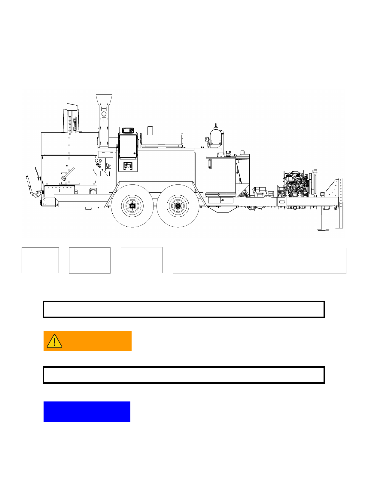
NOTE: This general outline will familiarize you with this machine dependent on model,
location and style and may vary with options installed. Read through the entire manual before
putting this machine into operation.
1) Main Control Panel: The main control panel is used to control the primary functions of the melter,
including simple automated user controls for Off / Run / Clean Out / Cool Down as well as manual control
of the sealant material pump direction and tank agitator. You can also monitor or adjust the temperature of
the sealant material and heat transfer oil on the control sub panel. See page 10 for more information on
the main control panel.
2) MA4 Applicator Electronic Control Display: This computerized panel will allow you to set your
application rate and calibrate the output rate of the sealant material through the application bar. See page
11 for more information on the electronic control unit.
3) Loading Door: Place the sealant material block or biscuit on the open door to load the melting
tank. See page 14 for more information on safely loading sealant material into the melter.
4) Heat Transfer Oil Level Dipstick: Allows you to monitor the amount of heat transfer oil in the
melter oil tank. See page 25 for more information on using the heat transfer oil dipstick.
5) Heat Transfer Oil Temperature Gauge: Displays the heat transfer oil temperature.
6) Ignition Switch: Engine key “ Start” / “ On” / “ Off” and also displays engine running hours, glow
plug status, alternator charge, engine oil pressure and engine coolant warnings.
7) Main Tank Valve: “ Open” / “ Shut” allows sealant material to enter pump from sealant material
tank.
8) Control Handles (Qty. 2): Controls flow from “ Circulation” re-circulation back to sealant material tank
and “Spray Bar Circulate” circulation through application bar and back to sealant material tank.
9) Bulk Loading Plug: This 3 inch Cam and Groove fitting allows for liquefied bulk sealant material to
be pumped directly into the MA4 sealant material tank from an external source.
10) Secondary Tank Valve: Allows sealant material to enter the Draw Off / Sample system out to the
Draw Off / Sample Valve.
11) Draw Off / Sample Valve: Allows sealant material to gravity pour into a pour pot for manual
application on areas unreachable by the application bar, or can be used for drawing off sealant material
samples for testing purposes.
12) Pour Pot Storage: Two pour pots can be stored in this external box. Items in this box must be tied
down properly while in transport.
13) Control Lights: These lights are visible to the driver and indicate when the system is ready to
begin application and that the vehicle is driving an appropriate speed for the application rate. See page 16
for more information on the control lights.
14) Ground Speed Encoding Wheel: This sensor folds up / down for storage and reports trailer speed
to the computerized control system. The control system communicates with the pump to apply the
appropriate amount of sealant material based on the speed reported by this wheel. See page 16 for more
information on the ground speed encoding wheel.
15) Application Bar: The application bar folds up / down for storage. When the control valves are
opened to “Spray Bar Circulate” hot sealant material circulates through the application bar until the system
is activated and senses movement, dispensing sealant material as directed by the control system.
16) Tip Control Keypad: You can manually control and engage the application tips from this keypad
(or with the key fob remote). See page 20 for more information on the tip control keypad
17) Key Fob Remote Transmitter: The MA4 comes with 1 wireless remote to activate the application of
sealant material from the application bar. The key fob remote transmitter also can control which of the 5
spray tips are actively applying sealant material. Note: Only one remote can be actively powered on at a
time. See page 16 for more information on the key fob remote transmitter. See page 20 for information on
pairing the key fob remote transmitter.
MA4 Feature Overview

10
MA4 Control Panels and Their Functions
MAIN CONTROL PANEL:
The Main Control Panel is used to operate the melter control system. Controls located on the outer
cover are for operating in AUTO mode only.
OFF: Shuts down power to the control panel, the sealant material pump, agitator and burner.
RUN: Allows the preprogrammed controllers to turn on the pump, agitator, and burner.
CLEAN OUT: Shuts down the burner and reverses pump flow direction to clean out material
from the spray bar and internal plumbing returning the sealant material to the material tank
COOL DOWN: - Shuts down the burner and sealant material pump and turns the agitator only.
This allows the material to cool down more consistently, extending the life of the material remaining in
the tank.
Inside the Main Control Panel box is a Sub Control Panel.
See pages 12-13 for detailed explanation of its use.

11
MA4 APPLICATOR ELECTRONIC CONTROL DISPLAY:
The MA4 Applicator Electronic Control Display is used to control the application rate of the sealant material
that is being applied. System status, spray bar position, material readiness, rate of flow and pump RPM are
all controlled by this computer control panel. Please note; If certain conditions are not met, the function will
be unusable (Gray). Some examples of conditions that are not met are: Spray bar is in stored position,
material is not up to application temp, etc.
ACTIVATED: Pressing the top left button (#1) on the Applicator Control Panel will switch between
“ACTIVATED” (Green) and “DEACTIVATED” (Red). Once the unit is activated, it will wait until the ground
speed encoding wheel registers a speed to start applying sealant material.
START: Pressing the second button on the left (#2) will switch between “ START” (Green) and
“STOP” (Red). This is typically turned on and off by using the key fob remote transmitter.
AUTO: Pressing the third button on the left (#3) will switch from “ AUTO” (Blue) and
“MANUAL” (Yellow). In the auto mode, the unit will control how much sealant material is applied by the
speed wheel as it moves across the ground. In the manual mode, the sealant material application will be
controlled by the pump speed that is set by the application rate.
APPLICATION RATE: Pressing the top right button (#4) will highlight the “ APPLICATION RATE”
function (Purple) and allow the dial knob to adjust the sealant material application rate. The sealant material
application rate is measured based on a pounds per linear foot measurement. Pressing the button again will
deselect the function (Gray) and the application rate is automatically calculated based on the speed of the
vehicle as reported by the ground speed encoding wheel.
TRIM: Pressing the second button on the right (#5) will highlight the “ TRIM” function (Purple) and
allow the dial knob to adjust the trim setting. The trim control compensates for a pump that is running slower
due to wear and will speed up the pump a certain % amount. Pressing the button again will deselect the
function (Gray). This feature is only usable while in the auto mode.
MA4 Control Panels and Their Functions
#1
#2
#3
#4
#5
Using the MA4 Applicator Electronic Control in “Manual” mode is only
intended for use by trained, experienced operators.
NOTICE

12
MA4 Manual Sub Control Panel and Its Functions
1)
2)
3)
4)
5)
6)
7)
8)
9)
10)
11)

13
1) MAIN CONTROL SWITCH:
Auto: (left position) Machine will operate from the systems preconfigured program using the
rotary switch control located on the outside front cover.
Off: (center position) Power to all systems will be off and burner, pump and agitator will stop.
Manual: (right position) Main rotary switch on front cover is no longer active. The three
switches below for temperature control, pump and agitator must be used to control the melter’s
operations.
2) TEMPERATURE CONTROLLER ON / OFF SWITCH: When this switch is on, the three digital
controllers to the right will be energized and they will be controlling the diesel burner and activate the
hydraulics for agitator motor and sealant material pump.
3) MATERIAL PUMP:
Seal (Forward): When this switch is on “ Seal (Forward)” the pump will be rotating with sealant
material recirculating back to sealant material tank. When key fob remote switch is activated, sealant
material will dispense out of the spray tips on the application bar.
Off: When the switch is “ Off” , the pump will not be rotating.
Clean-out (Reverse) Switch: When the switch is on “ Clean-out”, the pump will be rotating in the
reverse direction and will be drawing back any sealant material in the plumbing or the application bar
system back to the sealant material tank.
4) AGITATOR CCW / OFF / CW SWITCH: This switch controls the rotation of the agitator from counter-
clockwise (CCW) or clockwise (CW). If the switch is in the center position, the agitator will not rotate.
5) SEALANT TEMPERATURE CONTROLLER: The control system on your CIMLINE melter has been
factory set to run the most common types of sealant materials. See page 19 to override or change
settings.
6) MATERIAL READY LIGHT (Green): This LED light indicates that the sealant material has
reached the preset temperature if the unit is running in the auto mode.
7) HEAT TRANSFER OIL CONTROLLER: The control system on you CIMLINE melter has been factory
set to not exceed the OEM heat transfer oil limits for maximum temperature. It is advised to only use
heat transfer oil from CIMLINE. See Page 22 for heat transfer oil information and specifications.
8) AGITATOR READY LIGHT (Green): This LED light indicates that the heat transfer oil has
reached the preset temperature and if the unit is running in the auto mode, the hydraulic circuit for the
agitator will be activated. If enough sealant material has melted the agitator should be turning.
9) MATERIAL TANK TEMPERATURE CONTROLLER: The control system on your CIMLINE melter
has been factory set to engage the sealant material pump early enough to get a faster start up. See
page 19 to override or change settings.
10) PUMP READY LIGHT (Green): This LED light indicates that the sealant material inside the
pump has reached the preset temperature and if the unit is running in the auto mode, the hydraulic
circuit for the sealant material pump will be activated. If enough sealant material has melted the pump
should be turning and sealant material should be circulating through the system and back into the top
of the sealant material tank.
11) DIESEL BURNER LIGHT (Yellow): This LED light indicates that the material and heat transfer
oil temperature control are demanding that the diesel burner circuit is turned on.
MA4 Manual Sub Control Panel and Its Functions
CIMLINE recommends using the Main Control Panel in “AUTO”
control mode. “MANUAL” mode is provided for trouble shooting
and trained advanced/experienced users.
NOTICE

14
1. START ENGINE:
A) Turn key on engine control to “ 1”.
B) Allow 3-5 seconds to heat glow plugs (Flashing
green light will turn to solid green).
C) Turn key to “ 2”.
D) Release when engine starts.
MA4 Start Up Procedure
LOAD FRESH SEALANT MATERIAL INTO TANK:
All sealant material must be clean. Keep all foreign
matter out of melting tank to avoid damage to pump and
systems.
1) Open the material door (A) and place the block of sealant
material (B) on the open door against the holder (C).
2) Push door to the closed position.
TO PREVENT CONTACT WITH HOT SEALANT DO
NOT DROP MATERIAL INTO THE MELTER WITH
EITHER OR BOTH DOORS OPEN.
LOADING OPERATOR MUST WEAR ALL
PROTECTIVE CLOTHING COVERED ON PAGE 4.
LOAD MATERIAL FROM GROUND ONLY. NEVER
CLIMB ON THE TRAILER TO LOAD.
2. VERIFY SWITCHES ON CONTROL PANEL:
A) Verify main control switch inside control box is set
to “AUTO”.
B) Verify ALL the switches inside the control box are
in their left most position.
3. POWER UP CONTROL PANEL:
A) Set control panel rotary switch on front (outside)
of control box to the “RUN” position.
WARNING

15
4. PREPARE PUMP FOR SEALANT MATERIAL CIRCULATION:
When the green “MATERIAL PUMP ENGAGED”
light illuminates the sealant material pump should
be visibly rotating:
A) Open the main tank valve (A) at the pump,
turn to fully “OPEN”.
B) Visually check that there is smooth sealant
material recirculating into the top of the
sealant material tank.
C) Move both control handles (B) from “CIRCULATE
to “SPRAY BAR CIRCULATE”.
MA4 Start Up Procedure
5. ALLOW UNIT TO HEAT SEALANT MATERIAL TO CORRECT APPLICATION
TEMPERATURE:
The green “MATERIAL READY” light will illuminate when the
correct sealant material temperature is reached in the tank.
6. LOWER APPLICATION BAR:
Lower the application bar, close and secure the cabinet door.
7. LOWER THE SPEED SENSOR WHEEL:
Lower and secure the ground speed encoding wheel.
(A) (B)

16
RED
INDICATOR
LIGHTS
10. GROUND SPEED ENCODING WHEEL:
The ground speed encoding wheel has two red lights that are visible from
the tow vehicle.
A) The outboard “SYSTEM READY (SOLID)” light will
illuminate bright red and indicates when the computerized
control unit senses that the key fob remote is calling for
the application spray bar nozzles to be “ON” and applying
sealant.
B) The inboard “CORRECT SPEED (SOLID)” light will
illuminate bright red when the unit is traveling at an appro-
priate speed for the application rate programed. The light
will flash slowly if the unit is traveling too slow, and it will
flash quickly if the unit is traveling too fast for the sealant
material application rate.
9. KEY FOB REMOTE TRANSMITTER SPRAY CONTROL:
Use key fob remote transmitter to engage spray mode and control which nozzles are
active when ready to begin application of sealant material through the application spray
bar. NOTE: ONLY ONE REMOTE CAN BE USED AT A TIME. See page 20 for infor-
mation on pairing the key fob remote transmitter.
A) Power on the key fob remote transmitter using the “POWER ON / OFF” button at
the top of the remote.
B) When the key fob remote transmitter powers on, you should see the signal strength
light illuminate green indicating that the unit is on and communicating with the com-
puterized control panel.
C) Use the “START” (green) and “STOP” (red) buttons to begin and end application of
sealant material through the application spray bar.
D) The buttons numbered “1” through “5” control which spray nozzles are active on the application spray
bar while applying sealant material. Pressing a numbered button will activate and turn on a particular
nozzle and can be done “on-the-fly” while in application mode.
MPORTANT: To turn off a particular nozzle while in application mode, you must press the
“STOP” button momentarily to reset the hydraulics and halt application, then press the “START” but-
ton again to continue application with the new nozzle settings.
E) The red light at the top of the key fob remote transmitter will indicate when the battery is low and re-
quires recharging.
MA4 Start Up Procedure
8. ACTIVATE THE ELECTRONIC CONTROL DISPLAY:
Press the “ACTIVATED/DEACTIVATED” button on
the computerized applicator control panel.
A) Verify the top left button is set to
“ACTIVATED” and the light next to the but-
ton is illuminated green.
B) Verify the control unit is set to “AUTO” and
the light next to that button is illuminated
blue.

17
MA4 Clean Out/Shut Down Procedure
12. RAISE APPLICATION BAR AND RETURN TO CABINET, RAISE SPEED
WHEEL AND SECURE.
11. SET ROTARY SWITCH OUTSIDE CONTROL
BOX TO “CLEAN OUT”:
The “Clean Out” function on the control box will reverse the
sealant material pump and begin to evacuate the spray bar
and internal plumbing of a majority of the sealant material
and return it back to the tank. The entire procedure (steps
12-18) should be followed and all steps properly executed.
Following this process fully will increase start up efficiency
on the next job.
13. MOVE BOTH CONTROL HANDLES FROM “SPRAY BAR CIRCULATE” TO
CIRCULATE” AND CYCLE BOTH VALVES TOGETHER EVERY
2 MINUTES 5 TIMES TO FULLY CLEAR SYSTEM:
A) Move BOTH control handles (A) a minimum of 5 times,
every 2 minutes over a 10 minute period finishing
With both control handles in the
“Circulate” position.
14. CLOSE MAIN TANK VALVE (B) AT
PUMP, TURN TO FULLY “SHUT”.
15. SET ROTARY SWITCH OUTSIDE CONTROL
BOX TO “COOL DOWN”:
The “Cool Down” function on the control box will shut down all
functions on the MA4 except the sealant material agitator. The
cool down step should be run for a minimum of 30 minutes.
Following this process will allow the sealant material to more
evenly cool down and increase longevity of the material re-
maining in the tank.
16. SET ROTARY SWITCH
OUTSIDE CONTROL
BOX TO “OFF”.
17. TURN OFF ENGINE.
(B)
(A)

18
The amount of sealant material can be estimated by measuring the depth
of sealant material in the tank with the included depth gauge.
MA4 MATERIAL CAPACITY 410 GALLONS
Maximum safe operational sealant material tank capacity is 307 gallons.
20 Gallons
40 Gallons
TO ESTIMATE THE AMOUNT OF MATERIAL LEFT IN THE MA4 TANK:
A) Remove the depth gauge plate from the cabinet.
B) Open the material door and vertically place the depth gauge just barely touching the top of
the sealant material (B).
C) Count the number of slots showing from the top of the gauge down to the top of the material
tank ceiling. Count only the slots that are ABOVE the tank ceiling (C).
D) Multiply each slot shown above the material tank ceiling by 20 gallons, and that is
approximately what you have left in the tank.
Example: The above drawing shows the gauge is exactly on the 9th slot from the top. So, 8
slots are above the tank. 8 x 20 = 160. There is approximately 160 gallons of sealant material left
in the tank.
MA4 Sealant Material Tank Capacity
(B)
(C)
To maintain safe operation of trailer while in transport,
do not fill tank more than 75% of total tank capacity.
Approximately 307 gallons on the MA4.
WARNING

19
OTHER MELTER NOTES:
On a new CIMLINE Melter Applicator or a unit that has been idle for some time, it is recommended that you
slowly raise the oil temperature to 250ºF (121°C) and hold there for approximately 20 to 30 minutes. This
will help evaporate any water condensation that may be in the oil chamber.
To do this it will be necessary to temporarily change the heat transfer oil temperature setting.
The heat transfer oil control (B) on your CIMLINE melter has been factory set to 550° F (288°C). To
temporarily change the max temperature for evaporating condensation follow the same process as above
and apply to the heat transfer oil temperature controller (B). Run the melter applicator machine maintaining
the 250°F (121°C) heat transfer oil temperature for 20 to 30 minutes. Follow the instructions again to return
the heat transfer oil temperature controller back to the factory setting of 550°F (288°C).
MA4 Automatic Temperature Control Settings
MODIFYING SEALANT TEMPERATURE CONTROL SETTINGS:
The Sealant Temperature Control (A) on your CIMLINE melter applicator has been factory set to run the
most common types of sealants. These sealants have an application temperature of 325° F (163°C). With
some sealants, it may require a change to the controller to achieve the appropriate application tempera-
ture. To achieve this, open the control box and alter the Sealant Temperature Controller (top controller) by
following the directions below.
1) Press the “SET” button twice.
2) “SP1” (Set Point 1) is displayed.
3) Press the “SET” button.
4) Current material temperature setting is Dis-
played (factory default is 325°F (163°C).
5) Use the “Up / Down” arrow buttons to change to
the desired temperature.
6) Press the “SET” button.
7) Let the controller time out. The controller will
now be changed and the updates will be saved.
Decrease (DOWN)
Increase (UP)
Set
(A)
(B)
Modifying any of the MA4 Applicator Temperature Controls is only
intended to be done by trained, experienced operators.
NOTICE
Operating the heat transfer oil controller at temperatures higher than
the factory recommended 550°F (288°C) can risk death or serious
injury, equipment damage and will shortening the life of the oil.
WARNING

20
SYNCHRONIZING KEY FOB REMOTE TRANSMITTER AND RECEIVER:
1. Start with the power on the MA4 off (engine key in the “OFF” position).
2. Press and hold the key fob remote “POWER” button for 10 seconds until both LED’s flash together, then
release. This signifies that the transmitter is in teach mode.
3. Turn the MA4 engine key “ON”. The LED lights on the key fob remote will stop flashing after a few
seconds. Synchronizing is complete. You can confirm that the key fob remote is communicating with the
electronic control unit by observing the “Wi-Fi” icon on it’s display changing from red in color to blue.
USING THE TIP CONTROLER:
While the key fob remote transmitter is intended to be used from inside
the truck, the tip control panel is convenient to an operator working
near the back of the MA4 trailer. It is important to know that one can
override input form the other, so communication is crucial between
crew members when starting and stopping application.
A) Use the “START” and “STOP” buttons to begin and end
application of sealant material through the application spray bar.
B) The buttons numbered “1” through “5” (green/red lights) control
which spray nozzles are active on the application spray bar while
applying sealant material.
C) Pressing a numbered button will activate and turn on (green light)
or off (red light) a particular nozzle. Turning a nozzle “ON” can be
done “on-the-fly” while in application mode.
D) IMPORTANT: Due to the hydraulic pressure system, to turn “OFF”
a particular nozzle while in application mode you must press the
“STOP” button momentarily to reset the hydraulics and halt
application, then press the “START” button again to continue
application with the new nozzle setting.
Receiver
MA4 Key Fob Remote Transmitter Pairing
Key Fob Remote
Power Button
Crew communication is crucial to safety when
applying hot sealant material. Severe injury can
occur if the unit is activated unexpectedly.
WARNING
Table of contents
Other CIMLINE Melting Machine manuals