6
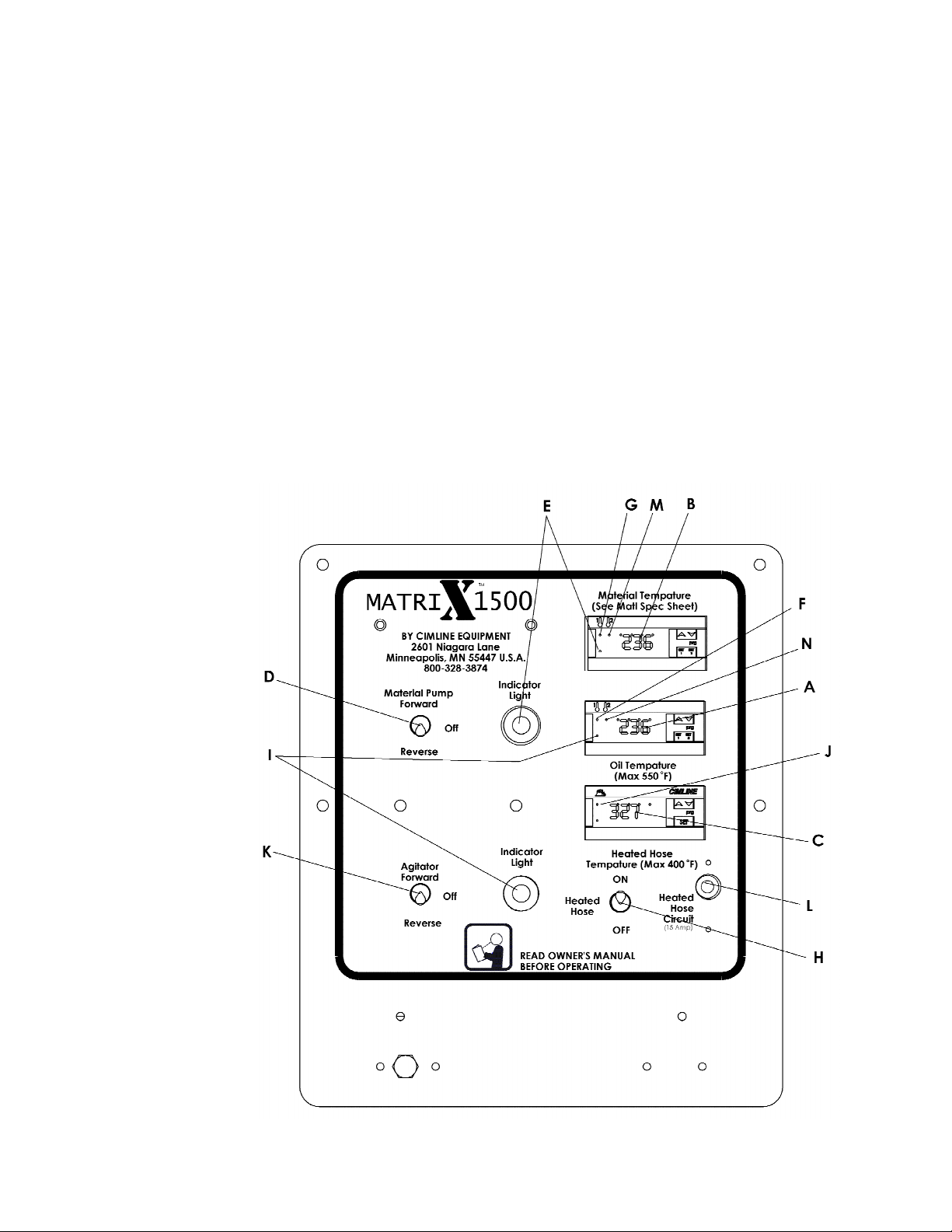
Controls and Their Functions
Controls and Their FunctionsControls and Their Functions
Controls and Their Functions
N TE: This general outline will only familiarize you with the machine. Read
N TE: This general outline will only familiarize you with the machine. Read N TE: This general outline will only familiarize you with the machine. Read
N TE: This general outline will only familiarize you with the machine. Read
through the entire manual before putting this machine into operation.
through the entire manual before putting this machine into operation. through the entire manual before putting this machine into operation.
through the entire manual before putting this machine into operation.
1) Access Port: The sealing wand is placed in here when not in use. This
allows operator to continue circulating material through the hose to prevent
material from cooling and freezing up.
2) Loading Door Place the material on safety door to load the melting tank.
3) Oil Temperature Gauge: Monitors the heat transfer oil temperature.
4) Material Temperature Gauge: Monitors the heat of the material in the
tank.
5) Pressure Valve: This valve controls the flow rate of the material being
pumped to the hose and sealing wand by changing the pressure setting.
(Turning the valve clockwise will increase the pressure which in turn will
increase the flow). During sealing operations, this valve alone can be used
to regulate flow.
6) Agitation Drive Control Switch: Flip this toggle switch to the forward-off-
reverse function.
7) Pressure Gauge: This gauge measures the pressure required to turn the
agitator. By observing this gauge, the operator can tell if the agitator is ro-
tating.
8) Pump Drive Control Switch: Flip this toggle switch to the forward-off-
reverse function.
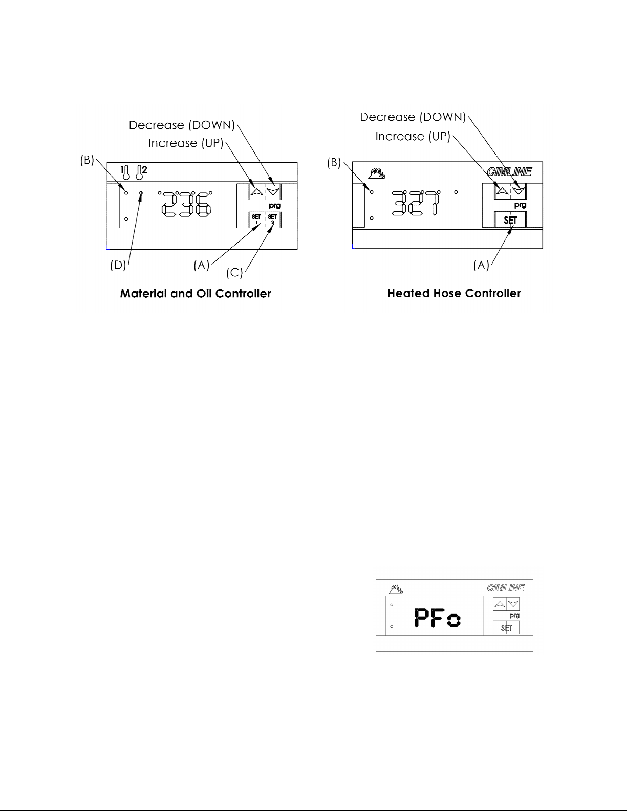
9) Temperature Control Box: This control allows the operator to set the de-
sired oil and material temperatures. The setting will be maintained auto-
matically.
10) Wand Holder: On models with the electrically heated hose, the wand is
placed into
this holder..
11) PSI Gauge: This gauge will tell you the amount of pressure in the hydrau-
lic system.
12) Ignition: This will allow you to start the engine. (This must be turned on
to allow the machine to start.
13) Pump Access Cover and Catch Tray: Open this door to access the
ump packings and the catch tray.
14)
14)14)
14)
Temperature Gauge:
Temperature Gauge:Temperature Gauge:
Temperature Gauge: This allows you to view the temperature of the cabi
net. If this temp. gets above 400 deg. F open the pump door.