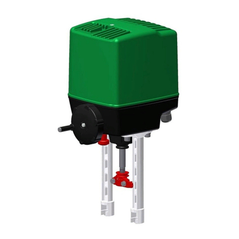
Circor Contromatics M6 Series User manual

Installation, Operation, andMaintenance
Manual for the
Contromatics M6Series
RACK AND PINION PNEUMATICACTUATORS
6th Edition

M6 SERIES IOM
6th EDITION
ISSUED 12/2014
2
TABLE OF CONTENTS
I.
Introduction...................................................................................04
A. Storage............................................................................................Pg.04
II.
Identification. ...............................................................................05
A. GeneralIdentification.....................................................................Pg.05
B. Actuator Part Identification............................................................Pg.06
III.
Specification................................................................................07
A. ActuatorWeights............................................................................Pg.07
B. Air Volume and Consumption....................................................... Pg.07
C. Speed ofOperation.........................................................................Pg.08
D. TemperatureSpecifications............................................................Pg.08
IV.
Operation.....................................................................................09
A. Principal of Operation (DoubleActing).........................................Pg.09
B. Principal of Operation (Spring Return)..........................................Pg.09
C.FailPositions..................................................................................Pg.10
V.
Mounting and Installation...........................................................11
A. Actuator Mounting Specifications.................................................Pg.11
VI.
Travel Stop Adjustment.............................................................12
A. Setting the Stops on Double Acting Units......................................Pg.12
B.
Setting the Stops on Spring Return Units (Fail Closed).................Pg.13
C.
Setting the Stops on Spring Return Units (Fail Open)...................Pg.14
VII.
Actuator Disassembly ...............................................................15
A. Steps to Actuator Disassembly.......................................................Pg.15
VIII.
Maintenance and Temperature Change................................19
A. Repair Kit Overview..................................................................... Pg.19
B.
Installing Repair Kits or Changing Temperature Rating............... Pg.20
IX.
Actuator Assembly .....................................................................21
A. Steps to Actuator Assembly..........................................................Pg.21
B. Spring Configuration.....................................................................Pg.26
C. Air Leak Testing............................................................................Pg.27
D. Changing Fail Position..................................................................Pg.28
X.
Automation Accessories...............................................................29
A.Speed Control.................................................................................Pg.29
B.Purge Block/Rebreather................................................................. Pg.30
C. Airlock............................................................................................ Pg.30

M6 SERIES IOM
6th EDITION
ISSUED 12/2014
3
TABLE OF CONTENTS
XI.
Torque Charts.............................................................................31
A.DoubleActing................................................................................Pg.31
B.SpringReturn................................................................................. Pg.31
XII.
Dimensional Information..........................................................................................34
XIV. Warranty ..................................................................................................................35

M6 SERIES IOM
6th EDITION
ISSUED 12/2014
4
I. Introduction
Contromatics offers one of the largest ranges ofpneumatic rack andpinion actuators onthe market.
Contromatics
actuators are designed tooperate with pressurized air, but will function equally aswell with
hydraulicfluid,
water orinert fluids. Our actuators are designed tooperate within the pressure range of 20PSIG
to 150 PSIG
and are offered intwo styles: the Double Acting model andtheSpring Return. The double acting
modelis
available in90°,120°,135° and 180° versions. The Spring Return version isavailable only asa 90°
model. The
double acting and spring return actuators can easily be field converted toother configurations by
insertionor
removal ofthe unique patented Contromatics springcartridges.
A. Storage
All actuators are factory lubricated for 2,000,000 cycles under normal operating conditions. The actuator
ports
are plugged to prevent liquids or other materials from entering the actuator during shipment. Ifthe actuators
are
to be stored for a long period of time before installation, the units should be stroked periodically to prevent the
seals from setting. (Note: the plugs must be removed in order to stroke actuator.) Recommended storageis
indoors, andthe units should be protected against weather andother harmfulelements.

M6 SERIES IOM
6th EDITION
ISSUED 12/2014
5
II. Identification
A. General Identification
Fig. 2.2
5
Fig. 2.3 Fig. 2.4 Fig. 2.5
1: Top auxiliaries interface. (VDI/VDE 3845;NAMUR)
2: Solenoid interface (VDI/VDE 3845;NAMUR)
3: Valve interface (ISO 5211, DIN 3337 patterns/w UNCthreads)
4: Spring return actuator (Closed)
5: Double Acting actuator (Open)
6: Actuator Serial Number
7: End Cap (Identical for spring return and double actingmodels)
Fig. 2.1

M6 SERIES IOM
6th EDITION
ISSUED 12/2014
6
B. Actuator Part Identification
ITEM #
Qty
Description
Material
1
1
Left End Cap
ASTM 384 Cast Aluminum
2
1
Body
6005T5 Extruded Aluminum
3
1
Upper Pinion O-Ring
NBR
4
1
FlangeBearing
Delrin
5
1
Pinion Washer
Stainless Steel
6
1
Pinion Circlip
Stainless Steel
7
1
Indicator
ABS
8
1
Indicator Screw
ABS
9
2
Piston
Anodized ASTM A23320
10
2
Piston O-Ring
NBR
11
2
Piston Guide
Bronze ImpregnatedPTFE
12
2
End Cap O-Ring
NBR
13
0-12
Spring Cartridge
Epoxy Coated Spring Steel
14
1
Right End Cap
ASTM 384 Cast Aluminum
15
8
End Cap Socket Head Cap Screw
Stainless Steel
16
2
Piston Skate
Delrin
17
2
Stop O-Ring
NBR
18
2
Stop Nut
Stainless Steel
19
2
Stop Bolt
Stainless Steel
20
2
Air Channel Plug
NBR
21
1
Thrust Bearing
Delrin
22
1
Pinion Cam
Electroless Nickel/Forged 1045 CarbonSteel
23
1
Pinion
Electroless Nickel/AlloySteel
24
1
Lower Pinion O-Ring
NBR
25
1
Lower Pinion Bearing
Delrin
Parts in Standard Kit

M6 SERIES IOM
6th EDITION
ISSUED 12/2014
7
III. Specification
A. Actuator Weights
"M" Series Weights (lbs)
Size
Weight For DA
Weight For K55
Single Spring Weight
200
3.00
3.30
0.03
300
4.65
5.05
0.04
500
5.75
6.25
0.05
700
7.65
8.65
0.10
1030
10.45
11.95
0.15
1400
13.25
14.75
0.15
2200
21.00
23.50
0.25
2900
26.85
30.35
0.35
4100
30.05
34.55
0.45
5800
45.05
51.55
0.65
9000
72.45
82.95
1.05
12100
87.20
104.70
1.75
23600
124.00
149.00
2.50
29500
180.00
222.00
4.20
B. Air Volume and Consumption
"M"
Series
Air
Vol ume
(i n
3
)
Si ze
Ope ni ng
Stroke
Cl os i ng
stroke
Per
cycl e
200
5.49
11.59
17.09
300
8.54
15.87
24.41
500
13.43
23.19
36.61
700
20.75
32.34
53.09
1030
30.51
56.75
87.26
1400
46.99
72.62
119.61
2200
76.28
104.96
181.24
2900
111.06
163.54
274.60
4100
131.81
195.28
327.09
5800
206.87
294.74
501.61
9000
341.12
484.53
825.65
12100
405.20
642.58
1047.78
23600
590.71
994.08
1584.79
29500
911.08
1502.40
2413.49

M6 SERIES IOM
6th EDITION
ISSUED 12/2014
8
C. Speed of Operation*
M Series Speed of Operation (sec)
Size
Double Acting Models
Spring Return Models
Opening Stroke
Closing stroke
Per cycle
Opening Stroke
Closing stroke
Per cycle
200
0.2
0.2
0.4
0.3
0.3
0.6
300
0.3
0.3
0.6
0.3
0.4
0.7
500
0.3
0.4
0.7
0.4
0.5
0.9
700
0.4
0.5
0.9
0.5
0.6
1.1
1030
0.6
0.6
1.2
0.7
0.9
1.6
1400
0.8
0.8
1.6
0.9
1.1
2.0
2200
0.9
1.1
2.0
1.2
1.4
2.6
2900
1.2
1.3
2.5
1.4
1.5
2.9
4100
1.4
1.4
2.8
1.5
1.8
3.3
5800
1.7
1.8
3.5
1.8
2.1
3.9
9000
2.4
2.5
4.9
2.5
2.8
5.3
12100
2.7
3.2
5.9
3.5
4.0
7.5
23600
3.5
4.0
7.5
4.1
4.6
8.7
29500
4.0
4.5
8.5
4.5
5.0
9.5
*These times are for reference only; operation speed will vary with field conditions and application.
D. Temperature Specifications
M Series Temperature Specifications
Temperature
Designation
Temperature
Range ( F°)
Temperature
Range (C°)
Bearing Material
O-ring Material Grease
Standard Temp
-4° to 176° -20° to 80° Delrin/Bronze Impregnated PTFE
NBR
Standard
High Temp
5° to 320°
-15°to 160° PPSU/Bronze ImpregnatedPTFE
Viton
High Temp
Low Temp
-58° to 176° -50° to 70° Delrin/Bronze Impregnated PTFE
Low Temp NBR
Standard

M6 SERIES IOM
6th EDITION
ISSUED 12/2014
9
IV. Operation
A.
Principals of Operation (Double Acting)
The Contromatics pneumatic actuator has simple operational characteristics. Port A is connected to the interior
cavity
between the pistons. Port B is connected to the end cap cavities (See Figures 4.1-4.2 below). If port A is
pressur-
ized (Fig. 4.1), air flows between the two pistons pushing them apart. Air is, in turn, exhausted out of port
B and
the pinion is rotated until the pinion cam is stopped by the open limit stop, resulting in the open position of
the
actuator. In order to rotate the actuator back to the closed position, air pressure must be removed from port A
and
applied to port B. Pressurizing port B (Fig. 4.2) will allow air to move into the cavities between the pistons
and the
endcaps pushing them together. Air is, in turn, exhausted out of port A and the pinion is rotated until the
pinion
cam is stopped by the closed limit stop bolt, resulting in the closed position of theactuator.
The above illustrations show the paths taken by the pressurized air (blue), the exhausting air (red), and the resulting
state of the actuator.
B.
Principals of Operation (Spring Return)
The opening stroke of the spring return model functions just like the double acting model. By pressurizing port A
as shown in Fig. 4.3 the actuator opens, exhausts air like the double acting model, and compresses the springs.
However, to close the actuator, air pressure is removed from port A and allowed to exhaust. Once this is done the
encapsulated springs will return the actuator to its closed position and air will be exhausted out of the A portas
detailed in Fig. 4.4 below.
The above illustrations show the paths taken by the pressurized air (blue), the exhausting air (red) and the resulting
state of the actuator.
A Port
B Port
A Port
B Port
A Port
B Port
A Port
B Port
NOTE:
In
the
case
of
a
spring
return
model
even
though
port
A
is
the
only
port
that
needs
to
be
pressurized
in
order
to
operate
the
actuator,
air
still
must
be
allowed
to
enter
and
exit
through
port
B
unobstructed
for
proper
operation.
Contromatics
both
recommends
and
supplies
filters
or
recirculation
blocks
that
will
maintain
airflow
but prevent
debris
from
entering
the
actuator.
Consult
Contromatics
for
specific
applications
and
more
information.

M6 SERIES IOM
6th EDITION
ISSUED 12/2014
10
C.
Fail Positions
The Contromatics actuator standard operation is counterclockwise to open and clockwise to close. This is referred
toas
a “fail clockwise” configuration or FCW. However, it is also available in an FCCW or “fail
counterclockwise”
configuration. Figures 4.5 & 4.6 show the same actuator with the piston and pinion orientation
changed to convert
the actuator from the FCW to the FCCW configuration. FCW is referred to as “fail closed”
and FCCW as“fail
open” due to its intended effect on the valve. In the diagrams below, the hollow arrows show
the directionthe
pistons move due to the spring force, and the solid arrows show rotation of the pinion as it travels
to thefail
position.
FCW (Fail Closed)Fig.4.5
Fig. 4.5 shows a FCW, spring return actuator going from the open position (left) to the fail, or closed, position
(right).
FCCW (Fail Opened) Fig.4.6
Fig. 4.6 shows a FCCW, spring return actuator going from the open position (left) to the fail, or closed, position
(right).
NOTE:
All
statements
above
assume
the
valve
is
a
quarter
turn
valve
that
opens
counterclockwise
and
closes
clockwise.
Further,
it
also
assumes
that
the
actuator
is
spring
return
Since
a
double
acting
actuator
will
always
fail
in
its
last
position
(discounting
any
forces
the
valve
may
exert
on
the
actuator).
See
also
Table
below.

M6 SERIES IOM
6th EDITION
ISSUED 12/2014
11
V. Mounting and Installation
A.
Actuator Mounting Specifications
The Contromatics actuator is designed to be easily installed. The standard M6 series comes with an ISObottom
mounting pattern and double square drive on the pinion allowing for simpler coupling fabrication. Additional
valve mounting patterns are available uponrequest.
MOUNTING DIMENSIONS
ISO dimensions represent
actuator mounting bolt circle.
ISO Bolt Circle A
B Bolt Size
ISO Bolt Circle C
D Bolt Size
Fig. 5.1
Bottom View of the
Contromatics actuator
with
ISO dimensions.
Model A Bolt Circle B Bolt Size C Bolt Circle D Bolt Size
200
1.97 1/4-20 1.42 10-32
300 2.76 5/16-18 1.97 1/4-20
500
2.76 5/16-18 1.97 1/4-20
700
2.76 5/16-18 1.97 1/4-20
1030
2.76 5/16-18 1.97 1/4-20
1400
4.02 3/8-16 2.76 5/16-18
2200
4.02 3/8-16 2.76 5/16-18
2900 4.92 1/2-13 4.02 3/8-16
4100
4.92 1/2-13 4.02 3/8-16
5800
4.92 1/2-13 4.02 3/8-16
9000
5.51 5/8-11 - -
12100
5.51 5/8-11 - -
23600 6.50 3/4-10 - -
29500
6.50 3/4-10 - -

M6 SERIES IOM
6th EDITION
ISSUED 12/2014
12
VI. Travel Stop Adjustment
Contromatics actuators have open and close travel stops for +5°/-5° oftravel.
A. Setting The Stops on Double Acting Units
1.
Operate the actuator assembly to the closed position.
2.
Remove/lockout the air supply to the actuator.
3.
Loosen the locknut on the closed stop.
4.
Turn the closed stop clockwise to reduce or counterclockwise to increase the travel.
5.
Retighten the locknut.
6.
Reconnect the air supply to check that the position desired is correct. If not repeat.
7.
Operate the actuator assembly to the open position.
8.
Remove/lockout the air supply to the actuator.
9.
Loosen the locknut on the open stop.
10.
Turn the top clockwise to reduce or counterclockwise to increase the travel.
11.
Retighten the locknut.
12.
Reconnect the air supply to check that the position desired is correct. If not repeat. items 7-11.
Open Limit Stop Closed Limit Stop
Fig. 6.1
The above illustration shows a double acting actuator in the open position and identifies the opening and closing
limit stops.

M6 SERIES IOM
6th EDITION
ISSUED 12/2014
13
B. Setting The Stops on Spring Return Units (Fail Closed)
1.
Remove the air supply to the A port. Actuator will move to the closed position. Please note the position
of the actuator.
2.
Apply air to open the actuator. Please note the position of the actuator in the open position.
3.
While the air supply is maintained carefully loosen the locknut on the closed stop and adjust the stop to
the correct position desired.
4.
Retighten the locknut.
5.
Remove the air supply and the actuator will go to the closed position desired.
6.
If the correct position is not achieved repeat 1-5.
7.
Loosen the locknut on the open stop and adjust the travel desired. (Clockwise adjustmentdecreases
travel.)
8.
Retighten the locknut.
9.
Apply air and check the open position. If not correct repeat instructions5-8.
Open Limit Stop Closed Limit Stop
Fig. 6.2
The above illustration shows a spring return actuator (FCW configuration) in the open position and identifies the
opening and closing limitstops.

M6 SERIES IOM
6th EDITION
ISSUED 12/2014
14
C. Setting The Stops on Spring Return Units (Fail Open)
1.
Remove/lockout the air supply to the actuator and it will drive to the open position. Note the position of the
actuator.
2.
Apply air to close the actuator. Note the position of the actuator while the air supply is maintained, loosen the
locknut on the open stop and adjust the stop to the correct positiondesired.
3.
Retighten the locknut.
4.
Remove/lockout the air supply to the actuator so that it opens, if it is not the correct position repeat items1-3.
5.
Loosen the locknut on the close stop and adjust the travel by the amount desired to give the correct position.
(Clockwise adjustment decreases travel.)
6.
Retighten the locknut.
7.
Reapply air and check the closed position. If not desired closed position repeat items 1-5.
Closed Limit Stop Open Limit Stop
Fig. 6.3
The above illustration shows a spring return actuator (FCCW configuration) in the open position and
identifies the opening and closing limitstops.

M6 SERIES IOM
6th EDITION
ISSUED 12/2014
15
VII. Actuator Disassembly
A. Steps to Actuator Disassembly
1.
Disconnect all electrical and air supplies from the actuator.
2.
Ensure the actuator is depressurized and in the fail position.
3.
Remove actuator from mounting bracket and coupling, and any limit switches, manual overrides, positioners
and other pneumatic accessories (where applicable), and place in a clean environment.
4.
Place actuator on end and evenly loosen all end cap screws until you are able to remove the end cap.
End Cap Scre
NOTE:
After
4-6
turns
of
the
end
cap
bolt,
the
springs
should
be
decompressed.
Fig. 7.1

M6 SERIES IOM
6th EDITION
ISSUED 12/2014
16
Fig. 7.3
5.
Remove any springs and repeat for the other side.
Spring Cartridges
Fig. 7.2
6.
Loosen both limit stop nuts then remove both limit stop bolts to allow full rotation of thepinion.
op Bolts

M6 SERIES IOM
6th EDITION
ISSUED 12/2014
17
7.
Rotate the pinion counterclockwise to push the pistons away from each other until they completelydisengage
from the pinion. (NOTE: This is for standard FCW configuration actuators. For non-standard units rotation may
be reversed. For possible actuator configurations see pg.11)
8.
Remove both pistons noting their orientation so they can be replaced in the same orientation duringreassembly.
Pinion
Piston
Piston
Fig. 7.4
9.
Remove pinion circlip, pinion washer, and flange bearing from top of pinion.
Fig. 7.5

M6 SERIES IOM
6th EDITION
ISSUED 12/2014
18
10.
Slide pinion down through the bottom of the actuator until you can remove the pinion cam, thrust bearing, and
upper pinion o-ring from the top of the pinion. Note the orientation of the pinion cam so it can be replaced in the
same position during reassembly.
Upper Pinion O-Ring
Thrust Bearing
Pinion Cam
Pinion Bearing
Lower Pinion O-ring
Fig. 7.6

M6 SERIES IOM
6th EDITION
ISSUED 12/2014
19
Maintenance and Temperature Change
A. Repair Kit Overview
Any time maintenance is preformed on an actuator, it is necessary to replace all O-rings, grease, and bearingsto
insure the longest life. During maintenance all parts should be wiped clean of grease using a clean cloth, and parts
should be lubricated with the fresh grease for the correct temperature application before reassembly. Beloware
diagrams showing the assembly of these parts and the contents of a Contromatics repairkit.
4
3
21 12
25 Fig. 8.2
24
Fig. 8.3
Fig. 8.1
Fig. 8.4
*Material will change to Viton for High temperature applications and a low temp NBR blend for low temperature
applications. **Material will change to PPSU for high temperatureapplications.
Fig. 8.5
Parts
List
for
Contromatics
Repair
Kit
Item
Qty
Part
Material
3
1
Upper
Pinion
O-ring
NBR*
4
1
Flange
Bearing
Delrin**
10
2
Piston
O-ring
NBR*
11
2
Piston
Guide
Bronze
Impregnated
PTFE
12
2
End
Cap
O-ring
NBR*
17
2
Stop
O-ring
NBR*
16
2
Piston
Skate
Delrin**
20
2
Air
Channel
Plug
NBR*
21
1
Thrust
Bearing
Delrin**
24
1
Lower
Pinion
O-ring
NBR*

M6 SERIES IOM
6th EDITION
ISSUED 12/2014
20
B. Installing Repair Kit or Changing Temperature Rating
Follow the listed steps to install a repair kit or change temperature applications. For reference the various
temperature specifications and materials can be found on pg. 9 of thismanual.
1.
Disassemble actuator as described in on pg. 21-24.
2.
Remove the O-rings and bearings from the various actuator components:
(See fig. 8.1-8.5 on the previous page for list of parts to be replaced and theirlocations)
a.
Piston O-rings (2)
b.
End Caps (2)
c.
Upper Pinion O-ring (1)
d.
Lower Pinion O-ring (1)
e.
Air Passage Plugs (2)
f.
Stop O-rings (2)
g.
Pinion Bearing (1)
h.
Thrust bearing (1)
i.
Flange Washer (1)
3.
Using mineral spirits (or other mild solvent), remove the lubrication from each actuator component. (Note:
clean all surfaces thoroughly prior to installation of new O-ring set.)
4.
Separate O-rings and determine the locations for installation:
a.
Piston O-rings: will be the thickest O-rings (2 pieces), (#10 fig. 8.2)
b.
End Cap O-rings: will have the largest O-ring diameter (2 pieces), (#12 fig. 8.3)
c.
Pinion O-rings: of the remaining O-rings, the largest is installed in the lower pinion
O-ring groove (#24 fig. 8.1). The second largest is installed on the top of the pinion (#3 fig. 8.1).
d.
Air Channel Plugs: the small cylinders fit in the ends of the body (2 pieces), (#20 fig.8.5).
e.
Stop O-rings: will have the smallest O-ring diameter (#17 fig. 8.4).
(Note: if these O-rings are not properly seated, they may be pinched during reassemblyand
subsequently leak.)
5.
Identify bearing parts and their installation locations:
a.
Piston Skates (#16 fig. 8.2)
b.
Thrust Bearing (#5 fig. 8.1)
c.
Flange Bearing (#4 fig. 8.4)
6.
Apply light grease to the internal portions of the actuator for ease ofreassembly:
a.
Inner bore of actuator.
b.
Piston wear surfaces (piston skate, piston bearing & piston O-Ring).
c.
Piston rack (apply on the full length of the pistonrack).
d.
Pinion gear teeth.
e.
Pinion wear surfaces and O-rings (both upper and lower areas).
7.
Assemble actuator as described on pg. 27-31. If the O-rings are difficult to install, the O-rings may be slightly
stretched and lubricated to ease installation. (Note: be sure to use the lubricant provided when lubricating the
O-rings.) When installing the end cap O-rings, be sure to seat the O-ring properly, a thin layer of greasewill
help hold the O-ring in place.
This manual suits for next models
14
Table of contents
Other Circor Controllers manuals