manuals.online logo
Brands
  1. Home
  2. •
  3. Brands
  4. •
  5. Circor
  6. •
  7. Tools
  8. •
  9. Circor HOKE 3HPST User manual

Circor HOKE 3HPST User manual

Continuously Improving
Flow Control
HOKE®
3HPST User
Instructions
Continuously Improving
Flow Control
Operation Instructions
For The Use with Fittings
Hydraulic Pre-Setting Tool (HPST) Operations Manual For
Model Number 3HPST
3HPST pre-setting tool was designed to initially set ferrules onto tubing prior to final make-up. Pre-setting assures correct and consistent
make-ups. Final manual make-up torque is reduced approximately by 30% of what would have been required without pre-setting.
2
PRE-SETTING HEAD
HAND PUMP HOSE
HAND PUMP
DIE & JIG LOCATION
WRENCHES
DIE FIXING BOLT
5mm HEX WRENCH
ASSEMBLY INSTRUCTIONS
HPST Setup
1. Connect hand pump to Pre-Setting head
The hand pump is supplied with a hose connected. Therefore the free
end needs to be connected to the Pre-Setting head.
1.1 Remove the hand pump and Pre-Setting head from the case
and place them in a suitable location.
1.2 Open the release valve on hand pump by turning the handle
counter-clockwise.
Operation Instructions
For The Use with Fittings
Hydraulic Pre-Setting Tool (HPST) Operations Manual For
Model Number 3HPST
3HPST pre-setting tool was designed to initially set ferrules onto tubing prior to final make-up. Pre-setting assures correct and consistent
make-ups. Final manual make-up torque is reduced approximately by 30% of what would have been required without pre-setting.
1.3 Remove the protective plug from the inlet connector on the
Pre-Setting head, turn counter-clockwise. Keep the plug in a
safe place, such as in the black case.
1.4 Connect the free end of the hand pump hose to the inlet
connector on the Pre-Setting head tightening the male and
female couplers together.
3
2. System Bleeding (Air Removal)
Perform the System Bleeding process prior to using the tool and
whenever any part of the hydraulic system has been disconnected.
2.1 Position the hand pump at a higher elevation than the
Pre-Setting head; this will help in chasing any trapped air out of
the hydraulic system. (See FIG 1, below)
2.2 Vent hand pump reservoir, by
turning the fill cap a 1/4 of a
turn to the “VENT” position and
ensure the hand pump release
valve is closed.
2.3. Turn release valve handle clockwise. Ensure the vent end of the
Hand Pump reservoir is the highest point in the system.
4
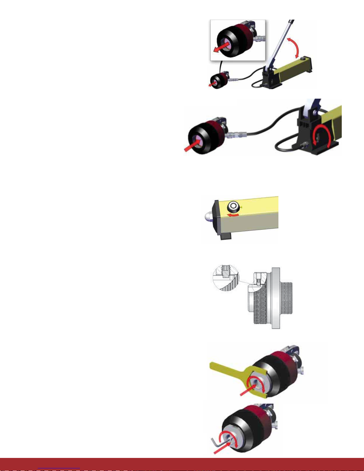
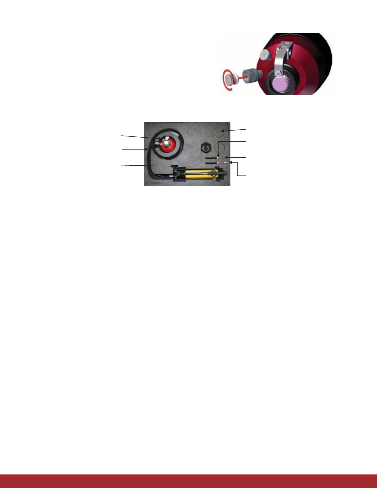
2.4 Operate the hand pump (pump the handle) until the piston in
the Pre-Setting head if fully extended. This is achieved when
the pump handle is hard to push. Do not try to pump the handle
any further. Pre-Setting head, turn counter-clockwise. Keep
the plug in a safe place, such as in theblack case.
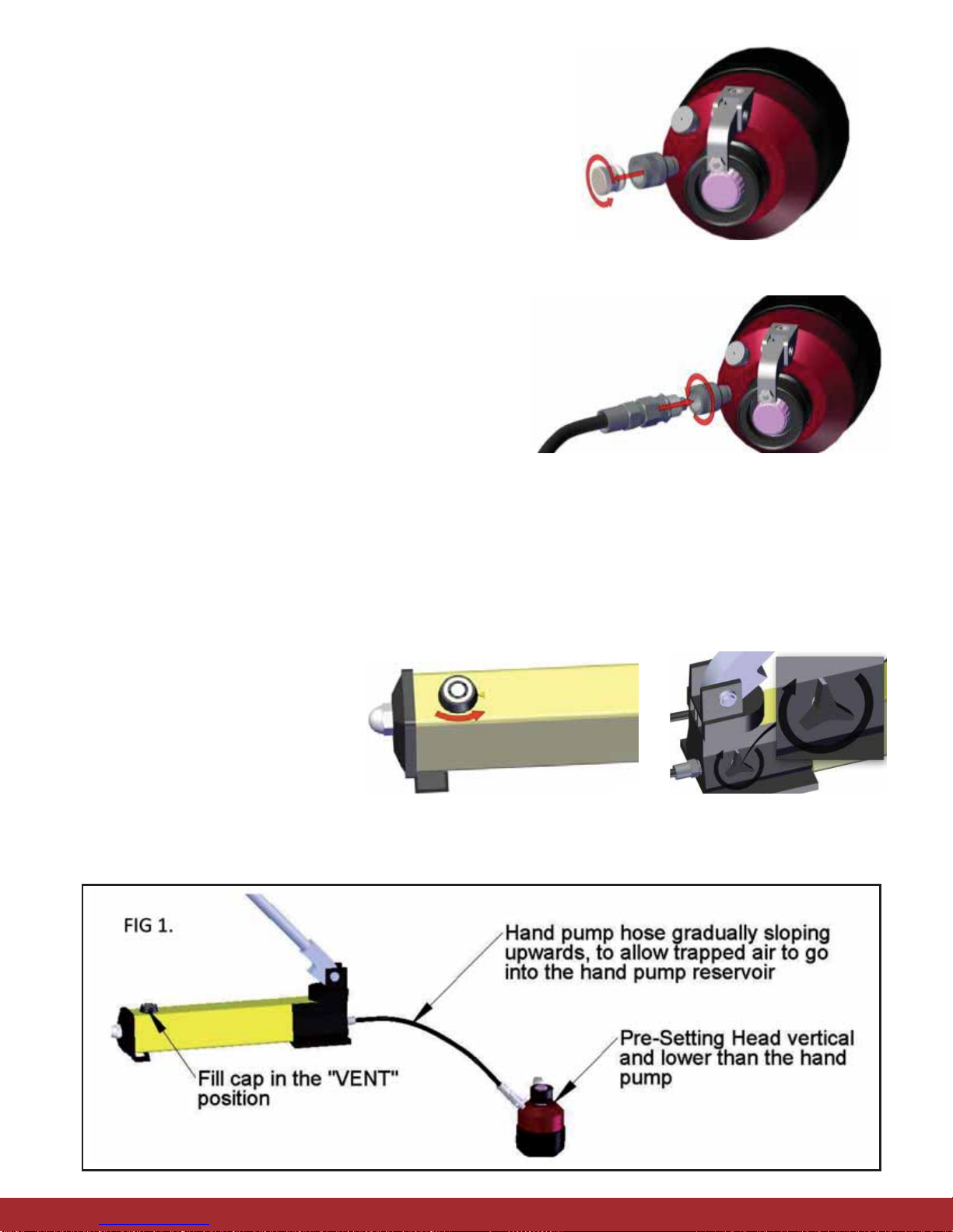
2.5 Open the release valve on the hand pump to retract
the Pre-Setting head piston. This action will force
any trapped air to move up into the hand pump reservoir.
2.6 Repeat the above step as necessary.
2.7 Add oil to the hand pump reservoir, if necessary.
Reference hand pump manufacturer’s manual
for instructions.
2.8 Return fill cap to the operating position (“CLOSE”).
3. Die and Jig Installation
Always keep the Die and Jig as a matched pair and stored in the black
case when not in use.
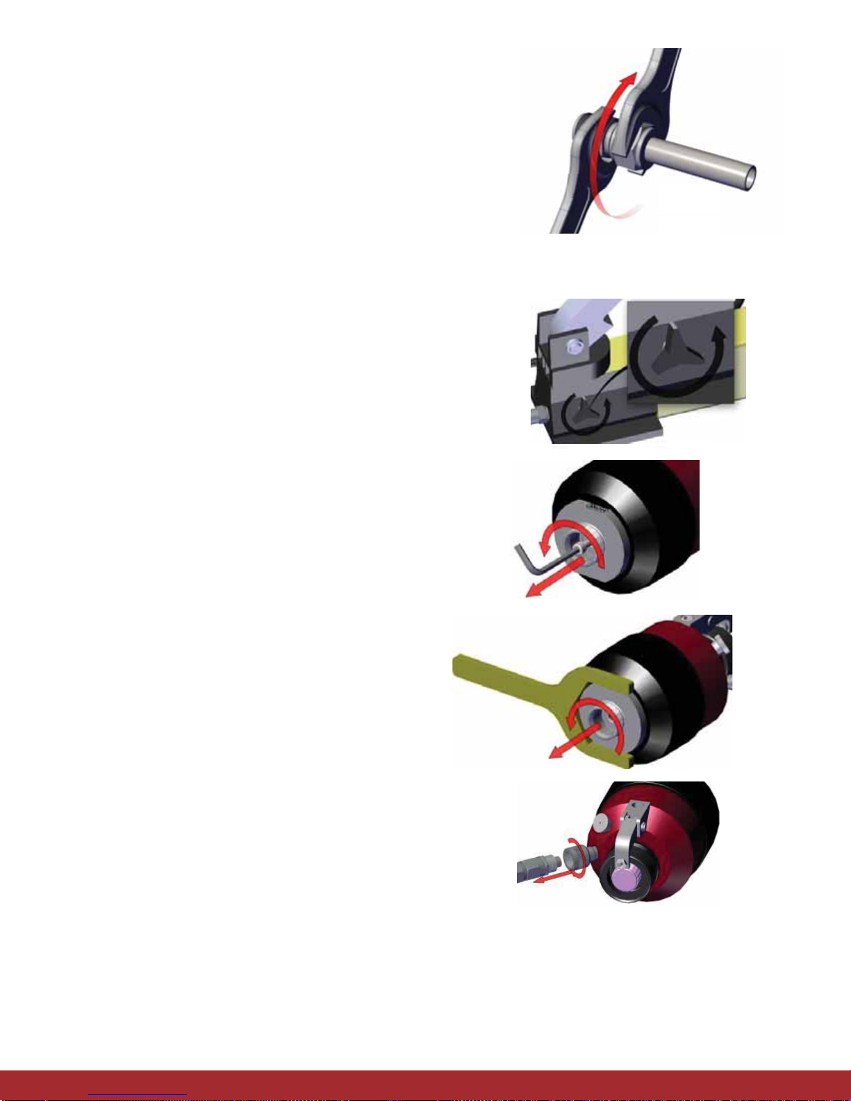
3.1 Select the corresponding Die and Jig set to the desired tube
size you wish to pre-set. Make sure the Die and Jig is a matched
pair. Use a 3/32 Allen Wrench to loosen the set screw located on
the large end of the jig (See adjacent figure). This ensures that
the Die moves freely prior to installing the Die and Jig assembly
into the Pre-Setting head unit.
3.2 Maintaining the Jig key in the Die slot, install the Jig and Die
by screwing the Jig into the Pre-Setting head and tighten
completely, turning clockwise. Do not over-tighten. Use ONLY
open-end wrenches provided.
3.3. Screw the Die-Fixing bolt to secure the Die onto the Pre-Setting
head’s piston, use the 5mm hex wrench, provided. Apply
a small amount of lube, provided with the fitting, to the
Jig threads. Do this on the first and every 5th use of the
tool thereafter.
Flexibility to
Your
Demand
Short &
Stable Lead
Times
Management
of Change
Services
Fit For
Purpose
Products with
Reduced
Variability
Resource
Optimization by
Addressing Your
Instrumentation
Needs
4. Indicator Nut Installation
4.1. Select the corresponding Indicator Nut for the fitting pre-set.
A. Black Indicator Nut is used with size 1/2” (12mm) only
B. Grey Indicator Nut is used with size 5/8” (14mm) and
above fittings
4.2. With the Indicator Arm in the release position, screw the
Indicator Nut on to the threaded piston shaft.
5. Tube Preparation
5.1 Ensure the tube outside diameter wall thickness and hardness
is within acceptable specifications. Free from scratches,
indentations and flat surfaces.
5.2 Make a square cut and remove any burrs from the end of
the tubing.
6. Ferrule Pre-Setting Procedure
6.1 With the Pre-Setting head in the desired location, ensure
the Indicator Arm is in the released position and the
required Die and Jig set installed.
6.2 Open the release valve on the hand pump
(turn counter-clockwise). Insure the end of the Die is
back from the end of the threaded portion of the Jig.
5
6
6.3 Fully insert a correctly cut, deburred tube into the HPST
head. Visually ensure both ferrules are correctly oriented.
Thread and rotate the nut until hand-tight.
6.4 Set the indicator arm in the operating position
by rotating the Indicator Nut counter-clockwise
until it stops.
6.5 Close the hand pump release valve (turn clockwise).
6.6 Pump the handle until the indicator arm releases.
CAUTION: Stop pumping immediately after the arm
releases, as over-pumping may cause the tube to
swell and stick.
6.7 Open the release valve on the hand pump.
Unscrew the nut and withdraw the pre-set
assembly from the Pre-Setting head.
6.8 The initial pre-setting is now complete. The
completion of the initial fitting make-up
can take place in the final location.
Repeat steps 6.3-6.8 for subsequent make-ups.
7
7. Finalizing the Fitting Make-up
7.1 Insert the end with pre-set ferrules and nut into
the fitting. Thread and rotate the nut until hand-tight.
While supporting the fitting body, tighten the nut
with a wrench 1⁄2turn for tubing up to 1” (25mm).
For tubing greater than 1” (25mm) 3⁄4turn is required.
The initial fitting make-up is now complete.
8. Dismantle & Store Unit
8.1 Open the Hand pump release valve.
8.2 Remove the Die and Jig from the Pre-Setting head
by first unscrewing the Die-Fixing bolt, using the 5mm Hex
wrench provided.
8.3 Remove the Die-Fixing bolt and store in a safe place.
Unscrew the Jig along with the Die, turning it
counter-clockwise, using the wrench provided.
8.4 Disconnect the hand pump hose from the female
coupler on the Pre-Setting head by loosening the coupler collar.
8
8.5 Plug the uncoupled end of Pre-Setting head with the protective
plug removed and stored earlier.
8.6 Store clean components and accessories in the black case.
8.7 Lay the black case down (horizontally), when possible,
during storage.
PRE-SETTING HEAD
HAND PUMP HOSE
HAND PUMP
DIE & JIG LOCATION
WRENCHES
DIE FIXING BOLT
5mm HEX WRENCH
9
Installation Appendix: Utilization of Used Fittings and Nuts
Fitting Manufacturing Warning
During the first make-up of a fitting the front ferrule is coined or seated with the fitting body. Coining is a
cold working process where a moderate amount of force is applied from the front ferrule to the body causing
slight plastic deformation which generates the sealing action of the ferrule and the body. During subsequent
remakes of the original body and ferrule; the ferrule re-seats and seals the connection to create a leak tight
connection. Therefore; if attempting to install a used fitting body with new ferrules it may compromise the leak
tight integrity of the fitting since the body was previously coined. Also, the nut and rear ferrule coin with each
other to create optimal driving force to seat the ferrules to the tube and create a leak tight connection. The
installation of used fittings and bodies may cause unintended leakage due to the installation of used hardware;
CIRCOR assumes no responsibility of the installation when used fittings are utilized, all warranties are voided.
All responsibility and liability for leakage and product failure remains solely with the installer.
Fittings up to and Including ½”/12mm – All Alloys
When using previously installed nuts and fittings with new ferrule sets (sizes ≤ ½” / 12mm) , the ferrules must
be set with new tubing using a manual pre-setting tool (PST). Refer to the “Manual Installation” instructions
above.
Over ½” / 12mm –All Alloys
When using previously installed nuts and fittings with new ferrule sets / (sizes > than ½” / 12mm), the ferrules
must be set with new tubing using the Hydraulic Pre-Setting Tool (HPST). Refer to the “HPST Installation”
instructions above.
3HPST-ENG • 01/16 • APS 4504
PO Box 4866
Spartanburg, SC 29305-4866
1-864-574-7966
www.hoke.com
sales-hoke@circor.com
The HOKE®Brand is just one product offering manufactured and supplied by
CIRCOR Instrumentation, an ISO 9001:2008 registered facility headquartered
in Spartanburg, SC, USA, a division of CIRCOR International (NYSE:CIR).
HOKE distributors are worldwide.
Contact us or visit our website to locate the nearest distributor to assure your
projects are consistently implemented across the globe with the greatest
Safety, Integrity and Reliability.
Our headquarters and manufacturing
facilities are located at:
405 Centura CT.
Spartanburg, SC 29303-6603 USA

Popular Tools manuals by other brands

RED ROOSTER RRI-4596R manual

RED ROOSTER

RED ROOSTER RRI-4596R manual

SUHNER ABRASIVE LXB 10 Technical document

SUHNER ABRASIVE

SUHNER ABRASIVE LXB 10 Technical document

Sunsight Azimuth Scope kit instructions

Sunsight

Sunsight Azimuth Scope kit instructions

Macnaught MATP1220 instruction sheet

Macnaught

Macnaught MATP1220 instruction sheet

Skil 1755 instructions

Skil

Skil 1755 instructions

AMES 2388340 operating instructions

AMES

AMES 2388340 operating instructions

Lincoln 84432 instructions

Lincoln

Lincoln 84432 instructions

Au Tour du Béton Scoot How to use

Au Tour du Béton

Au Tour du Béton Scoot How to use

Beechcraft Duchess 76 Pilot's operating handbook and faa approved airplane flight manual

Beechcraft

Beechcraft Duchess 76 Pilot's operating handbook and faa approved airplane flight manual

EINHELL Bavaria BHP 1500-2 operating instructions

EINHELL Bavaria

EINHELL Bavaria BHP 1500-2 operating instructions

Eraser BTS1 operating manual

Eraser

Eraser BTS1 operating manual

SNOWJOE Sunjoe SJ-GBT2 quick guide

SNOWJOE

SNOWJOE Sunjoe SJ-GBT2 quick guide

Bosch SKIL 4750 operating instructions

Bosch

Bosch SKIL 4750 operating instructions

RODCRAFT 5610 Operation manual

RODCRAFT

RODCRAFT 5610 Operation manual

U-Line H-2584 operating instructions

U-Line

U-Line H-2584 operating instructions

Rehau RAUTOOL L1 instruction manual

Rehau

Rehau RAUTOOL L1 instruction manual

LUMBERJACK TOOLS CF1040 quick start guide

LUMBERJACK TOOLS

LUMBERJACK TOOLS CF1040 quick start guide

Max HVR41G4 Operating and maintenance manual

Max

Max HVR41G4 Operating and maintenance manual

manuals.online logo
manuals.online logoBrands
  • About & Mission
  • Contact us
  • Privacy Policy
  • Terms and Conditions

Copyright 2025 Manuals.Online. All Rights Reserved.