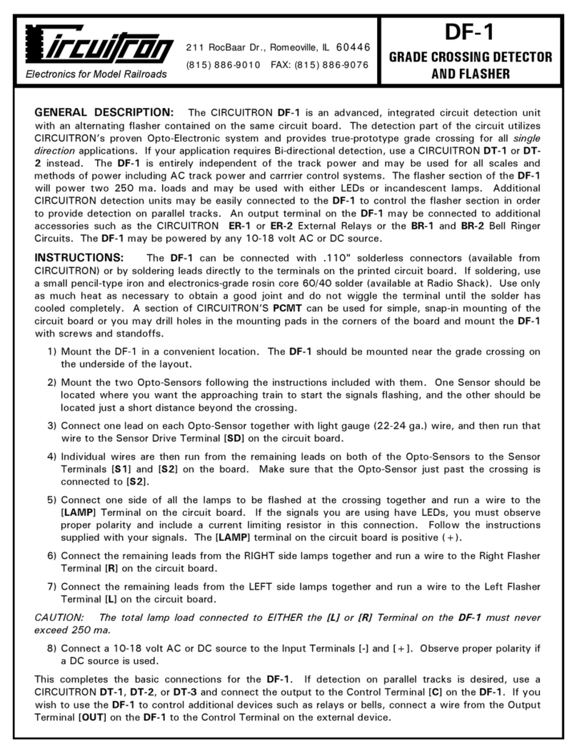
GRADE CROSSING DETECTOR
SINGLE DIRECTION
DT-3
211 RocBaar Dr., Romeoville, IL 60446
(815) 886-9010 FAX: (815) 886-9076
Electronics for Model Railroads
GENERAL DESCRIPTION: The CIRCUITRON DT-3 is an advanced, integrated circuit design
detection circuit which utilizes CIRCUITRON’S proven Opto-Electronic system. This circuit will
provide true-prototype grade crossing action for all single direction applications. The DT-3 is entirely
independent of the track power and may be used for all scales and methods of power including AC
track power or command control systems. There are absolutely no modifications to any piece of
rolling stock necessary. The output from the DT-3 provides a connection to common (ground) that
can be used to control DC powered devices such as flashers, bells, relays, etc. The output has a
current capacity of 250 ma. The DT-3 requires a 10 - 18 volt AC or DC input.
CIRCUIT DESIGN: The DT-3 uses a quad operational amplifier to provide all the functions of
detection and logic necessary. A small current flows through the two Opto-Sensors and is applied to
one side of a current comparator circuit. When the Sensor is shaded by a passing train, the current
decreases, and the output of the comparator turns on. These signals then trigger a bi-stable latch
whose output is used to drive the output transistor connected open collector.
INSTRUCTIONS: The DT-3 can be connected with .110" x .032” solderless connectors (available
from CIRCUITRON) or by soldering leads directly to the terminals on the printed circuit board. If
soldering, use a small pencil-type iron and electronics-grade, rosin core, 60/40 solder (available from
Radio Shack). Use only as much heat as necessary to obtain a good joint and do not wiggle the
terminal until the solder has cooled completely. A section of CIRCUITRON’S PCMT can be used for
simple, snap-in mounting of the circuit board or you may drill holes in the mounting pads in the
corners of the board and mount the DT-3 with screws and standoffs.
1) Mount the DT-3 in a convenient location under the layout in the vicinity of the grade crossing.
A section of CIRCUITRON’S Printed Circuit Mounting Track (PCMT) makes this a simple task .
2) Mount the two Opto-Sensors following the instructions included with them. One Opto-Sensor
should be located where you want the approaching train to start the signals flashing. The other
should be located a short distance beyond the crossing so that the signals will remain on until
the last car of the train has passed.
3) Connect one lead from each Opto-Sensor together with light gauge wire, and then run that wire
to the Sensor Drive Terminal [SD] on the circuit board.
4) Individual wires are then run from the remaining leads on each of the Opto-Sensors to the
Sensor Terminals [S1] and [S2] on the circuit board. Be sure that the wire from the Opto-
Sensor just beyond the crossing connects to [S2].
5) Connect a wire to the Output Terminal [OUT] and run it to the Control Terminal [C] on the
CIRCUITRON device that you want the DT-3 to control (Flasher, Bell Ringer, Relay, Turnout
Control, etc.) You may connect the DT-3 Output to more than one external CIRCUITRON
device if you so desire. NOTE: The DT-3 Output provides a connection to Common (Ground)
when a train is detected. The maximum current capability of the Output is 250 ma. This
Output may be used to control other manufacturer’s products as long as they are DC powered
and the current capability is not exceeded.
6) Connect a 10 - 18 volt AC or DC source to the Input Terminals [+] and [-]. Observe proper
polarity if a DC source is used. NOTE: If an AC source is used to power the DT-3 as well as a
CIRCUITRON Flasher unit, the inputs must be connected in phase for proper operation. To
avoid problems, connect all the [+] inputs together first, and then connect all the [-] inputs
together. Lastly, connect a source of AC to the string of devices. Use of a DC Source
eliminates these concerns and is highly recommended.
