8Installation
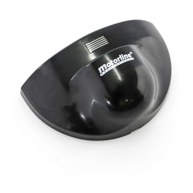
ODI100H
• Separate the alarm system cables from the mains cables.
The detector can be installed outdoors (according to the Class IV EN 50131-1).
• Avoid to direct the detector towards moving objects or, if impossible, please take
care in adjusting the detector in order to avoid false alarms.
• Be sure to install the cover with Fresnel lens before the detector testing. Without
cover, the detector doesn't work.
3-1Placement
Environmental conditions are important elements to be evaluated during the
installation. Bump, bottomland or slops can modify the performances of the
detector.
If into the detection area any medium size animal can walk, it is suggested to
choose carefully the installation height in order to avoid false alarms.
Installation height must be between 100 and 130 cm (not tilted ground).
Note
The maximum coverage range, 18m, is reached when the detector is installed at
about 120cm (height).
Do not obscure partially or completely the detector’s field of view.
COVERAGE TESTS
Once the detector has been powered, wait 3-4 minutes before running the
coverage test (the IR sensors need to be stabilised).
In order to obtain a real simulation, free the protected area, preventing more
people from moving inside the same area.
After 30-40 seconds of quiet, try to access the detection area by moving
perpendicularly to the beams, thus avoiding a frontal approach.
Check the operation of the two PIRs with the two green LEDs and the operation of
the microwave with the yellow LED.
Run the operation test, making sure to break the IR beams (table 5 - Top view e
table 6 - Side view) by moving perpendicularly to them.
Once detection has been achieved, wait for at least 7-8 seconds before trying to
be detected again.
3-2Mounting
1. Unscrew the screw for the cover enclosure (table 2, I).
2. Remove the cover with lens (table 2, D).
3. Set up for the steel bracket fixing (table 2, B) on the wall, or on a pole (be
sure the pole is stable and ripple free).
POLE FIXING
4. Position the two “U” (table 2, A) shaped bracket around the pole.
5. Block them with the inner screws (table 2, K) and the external screws
(table 2, J).
WALL FIXING
6. Perforate the wall in correspondence of the holes on the casing.
7. Insert the wall plugs into the holes.
8. Pull the wires through the wire entry on the steel bracket.
9. Fix the steel bracket on the wall or on the pole.
Note
Fix the metallic support on the wall perpendicularly to the ground.
10. Pull the wires trough the entry on the electronic holder (table 2, C). Perfo-
rate the cable passage knockout using a sharp point tool, as a screwdriver
or similar.
11. Locate the detector body on the metallic support and slide it down.
12. Screw up the detector body on the support using the 2 provided screws
(table 2, H).
13. Connect the wires to the terminals (table 3, L).
14. Run the range settings (PIR 2 position adjustment, PIRs sensitivity). See
paragraph 2-1 Detection range.
15. Close the detector with the front cover with Fresnel lens as shown opposite.
16. Screw up the metric screw (table 2, I).


