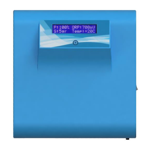
CircuPool RJ Series User manual


INTRODUCTION 1
GETTING STARTED 1
SAFETY INSTRUCTIONS 2
INSTALLATION
Overview 3
Installing the Control Module 4
Installing the Electrolytic Cell 4
Wiring 5
Installation Checklist 5
OPERATION
The Chemistry Involved 7
Adding Salt 7
Salt Levels 8
Using the Control Panel 10
MAINTENANCE
Ideal Chemistry Levels 13
Maintaining the Electrolytic Cell 14
HELPFUL HINTS 16
TROUBLESHOOTING 18
WARRANTY 20
RJ Series User Guide
Congratulations on your recent purchase of a CircuPool RJ Series
Saltwater Chlorine Generator. CircuPool’s high performance systems
offer escape from the routine of manual pool chlorination and
sanitization. Please take a moment to read through the entire manual
before installing your new unit. Your generator must be installed and
operated as specified.
READ FIRST
As with any electrical device, it is very important that the installation
and service of this equipment be performed by a qualified person
with the skills and experience required to do it safely and correctly.
Improper installation or service can result in severe electrical shock to
the installer or user of the equipment or pool. Please choose your
installer with great care!
TABLE OF CONTENTS
INTRODUCTION
GETTING STARTED
1

IMPORTANT SAFETY INSTRUCTIONS. READ AND FOLLOW ALL
INSTRUCTIONS. SAVE ALL INSTRUCTIONS.
WARNING: To reduce the risk of injury, do not permit children to operate this
device.
WARNING: Heavy pool (and/or spa) usage,and higher temperatures may
require higher chlorine output to maintain proper free available chlorine
residuals.
WARNING: Safe operation of the electrolytic cell requires a sufficient water
flow to fill the cell. Never operate the unit when the flow of water is restricted.
Always turn unit off when operating any plumbing control valves such as for
backwashing, water exhaust, or during operation of spa or water features if
operation restricts water flow to the cell.
WARNING: Follow all aspects of the *local and National Electrical Code(s) when
installing the CircuPoolRJ Series.
WARNING: We strongly recommend against the use of isolation valves. If
fullpump pressure is applied to isolated cell, it is prone to rupture.
If additional chlorine is required due to heavy bather loads, use Sodium
Hypochlorite to maintain an appropriate chlorine residual in the water.
Maintaining high chlorine and very high salt levels (above the
recommendedrange) can contribute to corrosion of pool (and/or spa)
equipment.
The maximum life of the electrolytic cell is 15000 hours under normal use
conditions.
DO NOT add acid directly to the skimmer. This may damage the cell.
Check the expiration date of any test kits as test results may be inaccurate
ifused after that date.
When replacing the cell, only use replacement cells having a label that clearly
states that it is the replacement for this RJ Series model.
For outdoor pools, chlorine residuals can be protected from destruction
bysunlight by addition of stabilizer (cyanuric acid).
For proper sanitation, spas must be completely drained periodically.
Thenumber of days between COMPLETE SPA DRAINAGE is equal to the volume
ofthe spa water in gallons, divided by 10 times the maximum number of
dailyspa users. Refill spa with water and repeat DIRECTIONS OF USE of this
device.
Note: Some local codes may require external grounding source. Check your local
ordinances.
The Control Module is to be mounted at least 3 feet above ground
level, and if possible protected from direct weather. The Electrolytic
Cell is to be plumbed in the return line to the pool, after the pump
and filter (and heater, if applicable).Water flow through the Cell can
be in either direction, and ideal Cell installation is horizontal. The
Control Module is to be connected to the pump system’s power
source, and the Cell Cable is to be connected from the Control
Module to the Cell.
SAFETY INSTRUCTIONS
INSTALLATION
Overview
2
3

TIP: Make sure the 6’ Cell Cable (DC power cord) can reach the
section of pipe selected for the cell.
Mount the Control Module as close to the pump
and filtration system as possible. For safety
concerns, do not install the Power Unit within 10
feet of the pool edges, and follow all applicable
codes.
Using screws, secure the Mounting Bracket at a
comfortable level on a wall or support. Once holes
are drilled into the wall and screws are tightly
secured, lift the Control Module onto the bracket,
and use additional screws to ensure that bracket
and Control Module are securely held in place.
TIP: After final installation steps, initially set the
output to 70% then adjust output (raise or lower) according to
chlorine demand.
TIP: Make sure the 6’ Cell Cable (DC power cord) can reach the section of
pipe selected for the cell, and that the pool pump is turned off before
installation.
The Electrolytic Cell is to be fitted into the return line as the last piece of
equipment the water passes through before returning to the pool: after the
pump, filter, heater (if applicable), etc. If a heater is present, all equipment
must be a minimum distance away, per manufacturer recommendations.
Measure and cut out a section of pipe (6 7/8”) at the desired location
in the return pipe, and install two 90° elbows glued to either side with
the openings facing up. Next, glue a minimum 6” pipe with a coupling
to each of the 90° elbows. Ensure barrel unions are tightened to the
cell prior to gluing to PVC (Note: for a
watertight seal, do not over tighten the
Collars, and only tighten them by hand).
There is no need to remove barrel unions
from the Cell body at the time of installation.
The O-ring connection is very tight when new
and dry, but will come apart easily when it is
time for cleaning. The cell is to be mounted
horizontally, with the inlet and outlet facing
down. This image denotes a standard 2”
plumbing install. If 1 ½” is required, simply
glue the pipe to the inside of the inlet/outlet
barrel unions, and utilize 1 ½” elbows.
Ensure that the RJ installation does not constitute a cross connection
with the local potable water supply. Consult local plumbing codes.
Power must be shut off at the circuit breaker before performing any
wiring. Be sure to follow local and NEC/CEC electrical codes. The
CircuPool RJ series has been designed to easily wire into typical in-
ground pool systems. To provide safe operation, the unit must be
properly grounded and bonded.
INSTALLATION, continued
Installing the Control Module
Installing the Electrolytic Cell
Wiring
4
5

The Control Module comes with a terminated power cord which is
typically connected to an external timer, which will turn the pump
and Control Module on and off together. As all individual wiring set
ups are unique, have the Control Module wired to the load side of the
timer by a qualified person. The RJ Series is shipped from the factory
with a 240 VAC configuration (unless otherwise requested). If a
120VAC is needed, call 888-206-9938. If unsure, immediately contact
a professional. In Canada and in some parts of the United States, the
Control Module must be connected to a circuit protected by a Class A
ground fault interrupter (GFI). Check local codes before connecting.
Always double-check the voltage of your power source. Connection
to improper voltage can: a) cause severe damage/harm, b) cause
lights and screen to power on without system function.
□Barrel Unions installed and glued into pipe work.
□Titanium Blade assembly is fitted tightly into the cell housing.
□All three Threaded collars on Cell are hand tight.
□Mounting Bracket is affixed to wall or support.
□Control Module is affixed to Mounting Bracket.
□Cell Cable from Control Module is connected to Cell.
□Control Module is connected to correct power source.
□You have checked and confirmed that Control Module switches ON
and OFF concurrently with filter pump.
□You have checked all connections and joints for leaks.
□Pool has properly balanced water chemistry.
□Sufficient salt has been added and fully dissolved and circulated
throughout pool water.
The RJ Series chlorine generator, by electrolysis, creates chlorine to
sanitize your pool from the salt molecules (NaCL) in your water. A
small electric charge is applied across a set of titanium plates inside
the Electrolytic Cell. This produces Sodium Hypochlorite (NaOCl). In
water, Sodium Hypochlorite dissociates into sodium (NA+) and
hypochlorite (OCl-) ions.
It is the hypochlorite ions that form with the hydrogen (H+) ions (from
the water) to form hypochlorous acid (HOCl), which is the active
agent that destroys bacteria and algae, and oxidizes organic matter.
This form of chlorine works quickly in the pipe, leaving only a mild
residual in the pool.
In addition, the Electrolytic Cell continuously “shocks” the incoming
water- burning off any oils, organic matter, or other particles that
need to be oxidized.
Use only evaporated, granulated, non-iodized salt (Sodium Chloride).
The purer the salt (at least 99%), the better the life and performance
of the Electrolytic Cell.
DO NOT add chemicals or salt directly to the skimmer. This may
damage the cell. If the Electrolytic Cell has already been installed, it
should be turned off before adding salt. For pools, it is best to empty
the required salt into the shallow end of the pool and run the filter
and pump simultaneously in order to circulate the water and dissolve
the salt (while the RJ Series is off). Do not throw the salt bag into the
water as chemicals and inks on the bag can interfere with water
balance.
CHECKLIST FOR INSTALLATION
Adding Salt
INSTALLATION, continued
The Chemistry Involved
OPERATION
6
7

Salt may take 24 - 48 hours to dissolve in summer, and longer in
winter. Finer granules of salt will dissolve faster than compressed
pellets.
Water Softener salt (also known as Water Conditioning pellets) is an
economical way to buy large quantities of salt. However, only salt
that is at least 99% pure NaCl can be used. Pellets are compressed
forms of evaporated salt that may take longer to dissolve. Avoid using
salt with anti-caking agents (Sodium Ferrocyanide, also known as YPS
or Yellow Prussiate of Soda) that could cause discoloration of fittings
and surface finishes in pool. Do not use Calcium Chloride as a source
of salt. Do not use Rock Salt; insoluble impurities mixed with the rock
salt can shorten the life of the unit.
The CircuPoolRJ Series can work within a broad salinity range, from a
minimum of 3000 ppm (parts per million), up to 4000 ppm. However,
the ideal level for operation is about 3500 ppm. To achieve this level
of salinity, add approximately 30 lbs of salt for every 1000 gallons of
water (or 3.6 Kilograms of salt for every 1000 Litres). If you are unsure
of the number of gallons in your pool, double-check with the
equations below.
Gallons (Measurements in Feet)
Rectangular - Length x Width x Average Depth x 7.5
Round - Diameter x Diameter x Average Depth x 5.9
Oval - Length x Width x Average Depth x 6.7
Before adding salt, check your water for any existing salt content and
add according to the chart below. If too little salt is added, the result
will be reduced efficiency and a low level of chlorine production. In
addition, operation at low salt levels will reduce the longevity of the
cell. The salt in your pool is constantly recycled, and the loss of salt
throughout the swimming season should be small. This loss is due
primarily to the addition of extra water to replace water lost from
splashing, backwashing, and draining. Salt is not lost due to
evaporation.
Salt Levels
OPERATION, continued
8
9

1) On / Off
For normal operation, the system should be left in the “On” position. In this
position, the CircuPool RJ Series will produce chlorine according to the desired
output %. When using an external timer to provide power, the system will
return to the last settings entered each time power is restored.
2) OK Button
Holding this button in for 5 seconds will open a menu that accesses the internal
timer settings and choice of language. Pressing once selects desired setting.
a. Language: Use arrows to change the language setting.
b. Which Timer to Use: External is the standard setting. For specific
situations, the Internal timer can run the unit independently of your
pump timer, follow the steps below:
i. Use the arrow keys to change it from external to internal timer
and press OK to accept the setting.
ii. Enter both ON and OFF times (see procedure below for setting
clock). Note: programmed times cannot overlap. Pump operation
must be ensured during run times.
iii. Ensure correct time on clock.
iv. Press OK to accept the settings
c. Setting the Clock: Use the arrows to change the digits and the plus/minus
buttons to move the cursors from hours to minutes.
3) SuperChlor
a. When you have an abnormally high bather load, a large amount of rain, or
a cloudy water condition which needs an extra amount of purification to
be introduced, simply press the SUPERCHLOR button. This electronically
“super chlorinates” the water for 24 hours, or until the power has been
turned off.
4) Winter Mode (non-freezing climates only)
a. During periods of decreased chlorine demand due to lower temperatures,
it is advisable to activate the WINTER MODE. Simply press once, and the
Winter Mode will accordingly reduce the chlorine output of the shown
percentage by approximately half. Reducing chlorine output during
periods of low activity will help maximize the life of the cell.
5) Manual Override
a. This button allows you to temporarily override the internal timer (if used),
without having to change the unit’s settings. Press once to enter manual
operation. When ready to return to normal automation, simply press the
button again.
6) Chlorine Output Levels
a. Pressing the + or –buttons with change the CHLORINE PRODUCTION in
10% increments.
7) Salinity Test
a. Press this button to recall the last salinity test. Each time the unit is
powered up, it performs several self-checks and a salinity test that takes
about 4 minutes. The keypad is disabled during these tests. After the
testing is complete, the salinity status will appear in the display. The
reading on Polarity One may differ from Polarity two. This reading may
also vary somewhat from independent tests done at the pool store or at
poolside. Most electronic testers are subject to a variation of about
fifteen percent. The CircuPool unit works well in a wide salinity range so a
great deal of precision is not required. High salt conditions will not harm
your CircuPool unit. With rain and backwashing, your pool’s salinity will
gradually diminish. Simply add a 40 lb. bag of salt whenever your salinity
level is low. TIP: When adding large quantities of salt, start with an
independent test of the existing salinity level and add in portions,
retesting at each stage.
8) Left and Right Arrows
a. Pressing the arrows will enable navigation through the menu options.
OPERATION, continued
Using the Control Panel
10
11

• On/Off LED Indicator
When illuminated, the CircuPool RJ Series has input power activated.
• Polarity 1 & 2 LED Indicator
One Polarity LED at a time will be illuminated, indicating which operation
cycle the unit is on. The system automatically switches polarities in order to
inhibit the build-up of calcium and other minerals on the cell as part of its
self-cleaning feature.
• Water Fault
When illuminated, the flow sensor has detected no water flowing. The
system will have stopped producing chlorine as a safety measure. Severe
low salt conditions will also activate the “Water Fault” warning light.
• Add Salt
The CircuPool RJ Series will automatically let you know if salinity has fallen
below acceptable levels. When illuminated for more than two hours, add
more salt as needed. The amount required varies with pool size (for pools
under 30,000 gallons, start with one 40 lb. bag).
• Over Salt
When illuminated, the salt content is more than sufficient. Unless salinity
levels are in a caustic range, no action is required. (Pool heaters, high Total
Dissolved Solids, and certain contaminants can cause false salinity readings.)
By familiarizing yourself with the operation of the RJ generator, you can
achieve the maximum performance for your pool. When chemical levels are
in the recommended range, there are four factors that you can control
which directly contribute to the amount of chlorine the RJ will generate:
•Pump run-time each day (hours)
•The amount of salt in the pool
•The chosen percentage of Chlorine Output
•Stabilizer level in the water.
To find the optimum % Output setting, start at a fairly high setting and work
downward. It will take a few days of adjustments to find the ideal setting for
your pool. Once determined, it should only take minor adjustments.
Swimming Pools Spas
Free Available Chlorine 1.0 - 3.0 ppm 3.0 - 5.0 ppm
pH 7.2 - 7.8 7.2 - 7.8
Total Alkalinity 100 - 200 ppm 100 - 200 ppm
Calcium Hardness 200 - 300 ppm 150 - 200 ppm
Stabilizer (Cyanuric Acid) 50 - 75 ppm 50 - 75 ppm
Saturation Index -0.2 to +0.2 -0.2 to +0.2
• Chlorine Stabilizer (Cyanuric Acid)
Stabilizer is needed to maintain proper levels of chlorine; the sun’s UV radiation can
destroy unstabilized chlorine in 2 hours. Stabilizer should be maintained between
50-75 ppm.
• Nitrates and Phosphates
These chemicals can cause extremely high chlorine demands and will deplete
chlorine from your pool. In some cases, they may even lower your chlorine levels to
zero. Your local pool professional can test for Nitrates and Phosphates, levels
should be at zero.
• Langelier Saturation Index
A calculated number used to predict the calcium carbonate stability of water. If the
index is higher than +0.2, it can cause excessive calcium scaling on the salt cell. If
the index is lower than -0.2, it can cause the water to be corrosive to the titanium
on the salt cell.
• Metals
Metals can cause the loss of chlorine. Also, metals can stain your pool and tint your
water. Have your local professional test and recommend methods of removal.
• Chloramines
Chloramines should not be present in pool water. When organic materials are not
fully oxidized by Free Chlorine, Chloramines are formed. This ties up the Free
Chlorine in your pool, and does not allow the chlorine in your pool to disinfect.
Chloramines also cloud pool water and burn the eyes. Super Chlorinate (shock) to
remove Chloramines at the initial startup of the pool.
OPERATION, continued
MAINTENANCE
Ideal Chemistry Levels
12
13

• pH Levels
pH produced by the Electrolytic Cell is close to neutral pH. However, other factors
usually cause the pH of the pool water to rise. Therefore the pH in a saltwater pool
tends to stabilze at approximately 7.8. This is within national standards. If the pool
pH rises above 7.8, have a pool professional test to see if other factors such as high
Calcium Hardness or Total Alkalinity are the cause, and then balance accordingly.
• Total Dissolved Solids (TDS)
Adding salt to pool water will raise the TDS level. While this does not adversely
affect the pool water chemistry or clarity, the pool professional testing for TDS must
be made aware that salt has been added. The individual performing the TDS test
will then subtract the salinity level to arrive at the correct TDS level.
As a natural result of the electrolytic process which creates chlorine
from salt molecules, a white mineral build-up is attracted to the
titanium plates in the cell. The self-cleaning feature helps to inhibit
such build-up and scaling. However, the attraction of minerals is
inevitable, and eventually it must to be removed. The cell only needs
cleaning to ensure that build-up (or any other foreign matter) does
not cause individual plates to come in contact with each other. With
correct water chemistry, the cell will only need cleaning once or twice
a season (about every 6 months).
When removing the cell for cleaning or replacement:
1) Turn off all power, close return line valves if applicable.
2) Remove the cell plug connecting the cell to the Control Module.
3) Unscrew threaded rings around the PVC piping connecting
the cell to the return line plumbing.
4) Pull entire cell away from the barrel unions.
To clean the cell of any mineral buildup:
1) Orient the removed cell so that the inlet and outlet point
towards the sky. Place on the ground and stabilize so as to
remain upright and prevent spilling.
2) In a separate bucket, mix one part muriatic acid into four parts
water. Pour this weak acid solution directly into cell.
3) Allow solution to soak for NO MORE THAN TEN MINUTES.
4) Properly dispose of acid solution and use a hose to generously
rinse the cell.
5) Reinstall cell into PVC return line.
Note: Cleaning the cell is only necessary to remove an excessive
build-up of minerals on the plates. A light coating of minerals does
not impede performance. Excessive cleaning will reduce lifespan
of the cell.
Winterizing the Cell
The Electrolytic Cell will be damaged by freezing water just as your
pool plumbing would. In areas which experience severe or extended
periods of freezing temperatures, be sure to drain all water from the
pump, filter, supply and return lines before any freezing conditions
occur. The Control Module is capable of withstanding any winter
weather and does not need to be removed.
Replacing the Cell
When the titanium blades inside the Electrolytic Cell have reached
the end of their lifespan, replacements are available so that the
whole system does not have to be removed. Replacements are easily
switched out. To ensure quality and value, only genuine CircuPool
replacement parts may be used.
OPERATION, continued
Maintaining the Electrolytic Cell
14
15

For more detailed informationand useful tips, visit
www.circupool.com/help.
Proper operation of the chlorine generator can be easily verified by
inspecting the Electrolytic Cell. The chlorine being produced will appear as a
fog at one end of the plates. However, if the pool remains cloudy, or the
chlorine residual tests low, then the chlorine being produced is being lost
due to high chlorine demand or improper water conditions.
To reduce the chlorine demand, check the pH and Stabilizer (Cyanuric Acid)
reading. Check for phosphates and nitrates, which commonly contribute to
severe chlorine demand. If tests show correct, then a shock treatment with
an oxidizer agent is advised. Generally, superchlorination is not necessary if
the pool is maintained at correct levels.
Recommended List
• Read and keep your manual in a safe place.
• Increase Chlorine Production when temperature goes up.
• Increase Chlorine Production when number of guests goes up.
• Use Stabilizer (Cyanuric Acid) to protect free chlorine in pool.
• Mount Control Module in shade or out of the direct sunlight whenever
possible.
• Decrease Chlorine Production when temperature goes down.
• Take pool water sample to a Pool Professional once per month.
Not Recommended List
• Do not allow fertilizer anywhere near your pool. Fertilizers are one of
many sources that contain Nitrates or Phosphates which cause severe
chlorine demand in pool water.
• Never use dry acid to adjust pH. A build-up of by-products can damage the
Electrolytic Cell.
• Do not add any pool water balancing chemicals (including salt) unless the
Control Module is turned off.
• Do not add any chemicals (including salt) to the skimmers.
• Do not let salinity level drop below 3000 ppm.
Algae
Plant-like organisms which grow in water.Especially active in summer
conditions, where chlorine disinfectant level is too low to destroy
them. Algae may be green, brown, or black (Black Spot) in color.
Chlorine Demand
The amount of chlorine that should be added to the water to provide
proper bacteria and algae control.
Chlorine Residual
The amount of chlorine left over, after the “demand” has been met.
Combined Chlorine
Weak chlorine which is combined with the contaminants in the water.
Free Chlorine
Active chlorine in the water with the potency to destroy
contaminants.
Shock Treatment
The removal by means of oxidation of those materials that have
chlorine demand.
Superchlorination
An extra large amount of chlorine added to the water.
HELPFUL HINTS
Recommendations and Helpful Hints
Definitions
16
17

For more detailed information and extensive troubleshooting, visit
www.circupool.com/help.
Power LED and LCD Screen Not Turning On
• Double verify whether connected to 120 or 240 VAC input power
• Verify connection internally to the proper screw terminals.
• Verify input voltage with a voltmeter.
• Check internal glass fuse or external fuse reset button (depending
on model).
Water Flow Through Cell is Low
• Check for air in system
• Check operation of pump
• Check filter is clean
• Check water level of pool
• Check for blockage in system
Low or No Chlorine Residual
The possible cause may be one or more of the following:
• Insufficient chlorine output %
• Insufficient running times
• Phosphates or Nitrates in the water
• Insufficient or excessive stabilizer
• pH too high
• Salt content below 2500 ppm
• Check wire connections
• Check reset breaker / fuse on Control Module
• Check filter pump running
• Check water flow through Cell is sufficient
• Cell needs cleaning
Water Fault LED Illuminated
• The Control Module has stopped generating chlorine. Check that
the Electrolytic Cell is completely filled with water.
• If there is adequate flow and the LED is still on, check that the
individual connections are tight and free of corrosion between the
female terminals on the Cell Cable and corresponding male brass
terminal.
TROUBLESHOOTING
18
19

CircuPoolRJ Series Saltwater Chlorine Generators are warranted by the
manufacturer, Compu Pool Products USA Inc., should defect occur due to
faulty manufacture or materials:
For residential use, Compu Pool Products USA warrants to the original
purchaser that the equipment shall be free of manufacturer’s defects at the
time of sale, and upon examination, shall provide replacement parts in
accordance with the following schedule:
First Year - Parts supplied at no cost.
Second Year - Parts supplied at 20% of normal price.
Third Year - Parts supplied at 40% of normal price.
Fourth Year - Parts supplied at 60% of normal price.
Fifth –Seventh Year - Parts supplied at 80% of normal price.
For Commercial use in any “regulated pool”, all parts are warranted against
defect for a period of eighteen months.
The warranty may be void if the following occurs:
1. Damage beyond the control of CompuPool Products USA.
2. Damage due to improper pool chemistry.
3. Damage due to improper installation.
4. Damage due to failure to properly maintain unit.
5. Damage due to improper service.
6. Damage caused by insects or natural elements.
This warranty is applicable to parts only and CircuPool and Compu Pool
Products USA Inc., its agents, employees, and affiliates expressly disclaim
responsibility for loss, damage, or injuries to persons or property arising
from the use, or installation of equipment. Shipping and labor costs are the
sole responsibility of the purchaser. Warranty claims must be initiated in a
timely manner by calling 1-888-206-9938 and defective parts shall be
shipped for inspections, pre-paid, to CompuPool Products USA, 126
Semoran Commerce Place, Apopka, FL, 32703.
RJ Series User Guide
Notes:
WARRANTY
CircuPool Exclusive 7 Year Limited Warranty
20
Other manuals for RJ Series
1
Table of contents
Other CircuPool Water Filtration System manuals

CircuPool
CircuPool RJ16+ Operating instructions

CircuPool
CircuPool SJ20A Operating instructions

CircuPool
CircuPool CJ-1350 User manual

CircuPool
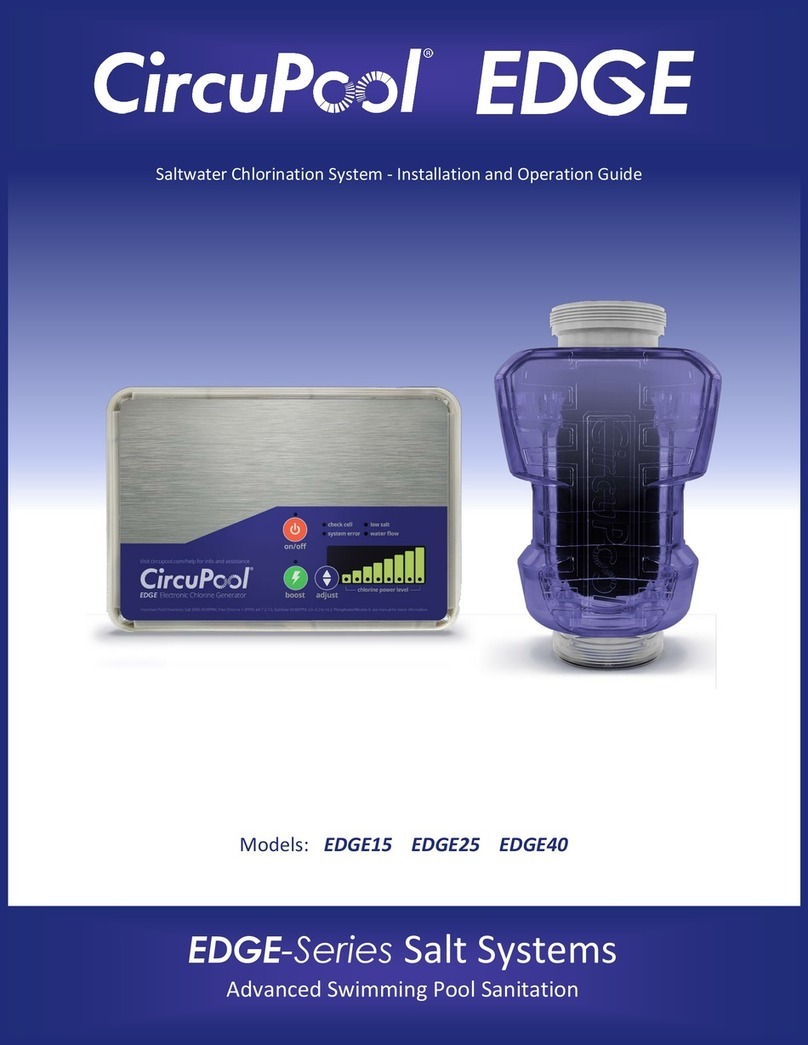
CircuPool EDGE Series Operating instructions

CircuPool
CircuPool Core Series Operating instructions

CircuPool
CircuPool SJ Series Operating instructions

CircuPool
CircuPool Universal UL-25 Operating instructions