HT PVCHECK User manual

Manual
PVCHECK
EAN: 8033772797467

PVCHECK
2
PVCHECK

PVCHECK
1
Table of contents:
1. PRECAUTIONS AND SAFETY MEASURES............................................................................3
1.1. PRELIMINARY INSTRUCTIONS........................................................................................3
1.2. DURING USE .....................................................................................................................4
1.3. AFTER USE........................................................................................................................4
1.4. DEFINITION OF MEASUREMENT (OVERVOLTAGE) CATEGORY..................................4
2. GENERAL DESCRIPTION........................................................................................................5
2.1. INTRODUCTION ................................................................................................................5
2.2. INSTRUMENT FUNCTIONS...............................................................................................5
3. PREPARATION FOR USE........................................................................................................6
3.1. INITIAL CHECKS................................................................................................................6
3.2. INSTRUMENT POWER SUPPLY.......................................................................................6
3.3. CALIBRATION....................................................................................................................6
3.4. STORAGE ..........................................................................................................................6
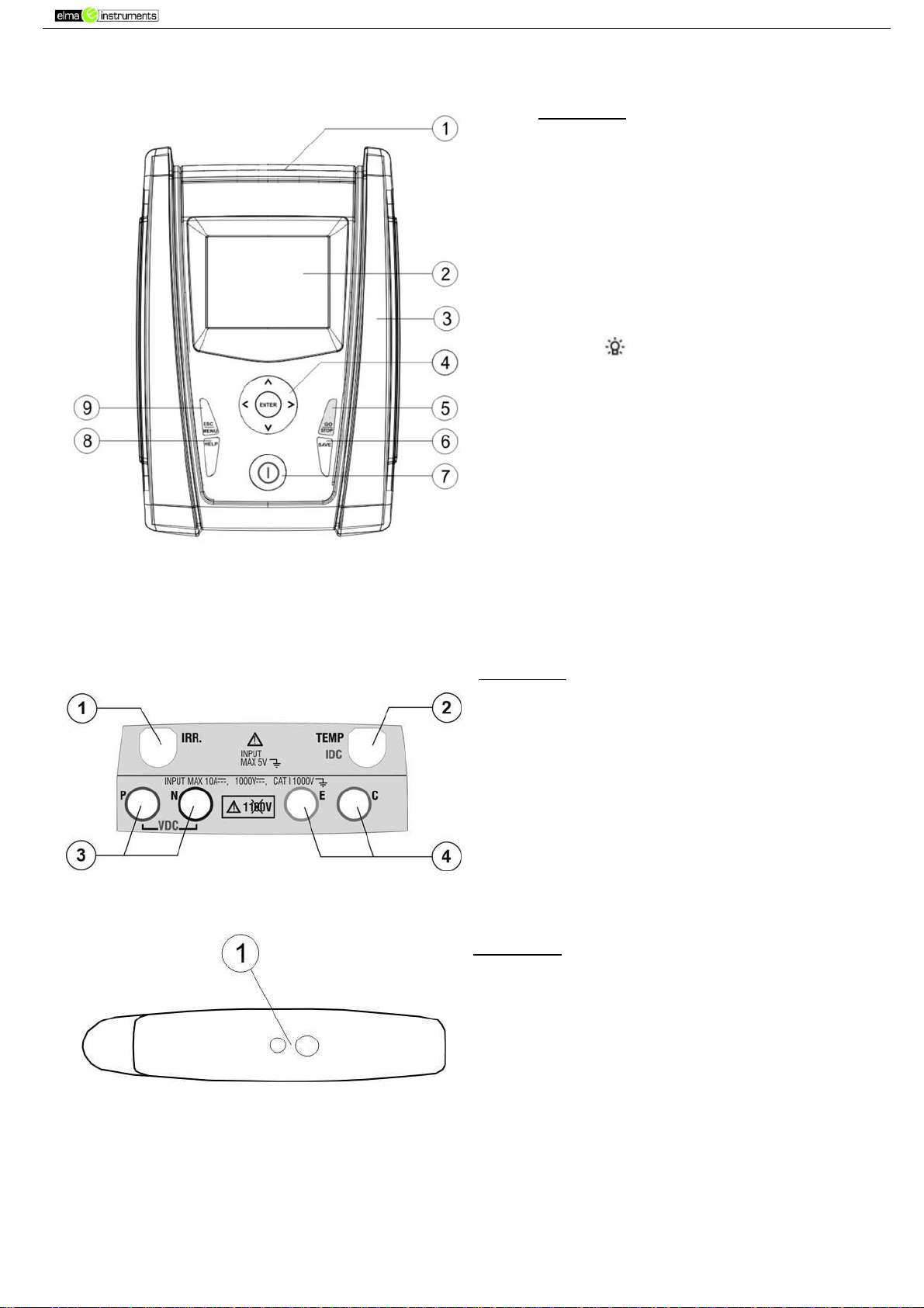
4. NOMENCLATURE ....................................................................................................................7
4.1. INSTRUMENT DESCRIPTION...........................................................................................7
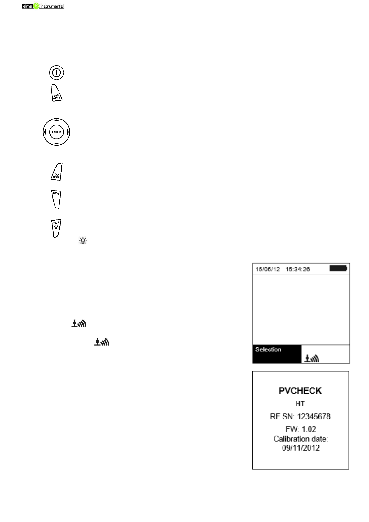
4.2. KEYBOARD DESCRIPTION...............................................................................................8
4.3. DISPLAY DESCRIPTION ...................................................................................................8
4.4. INITIAL SCREEN................................................................................................................8
5. GENERAL MENU......................................................................................................................9
5.1. SET –INSTRUMENT SETTINGS.......................................................................................9
5.1.1. General.........................................................................................................................9
5.1.2. Measuring unit............................................................................................................10
5.1.3. Date and time.............................................................................................................10
5.1.4. Remote unit/Pyranometer...........................................................................................10
5.1.5. Irradiance ...................................................................................................................11
5.1.6. DC Clamp...................................................................................................................11
5.2. EFF –EFFICIENCY TEST SETTINGS FOR PV INSTALLATIONS..................................12
5.2.1. Instrument settings.....................................................................................................12
5.2.2. System parameters ....................................................................................................13
5.2.3. Selection of the compensation relationship of temperature effects ............................14
5.3. LOWΩ–SETTINGS FOR CONTINUITY TEST WITH 200MA .........................................15
5.3.1. Instrument settings.....................................................................................................15
5.4. MΩ – SETTINGS FOR INSULATION MEASUREMENT...................................................15
5.4.1. Instrument settings.....................................................................................................15
5.5. IVCK –SETTINGS FOR IVCK QUICK TEST ...................................................................16
5.5.1. Instrument settings.....................................................................................................16
5.6. DB –DATABASE MODULE MANAGEMENT...................................................................18
5.6.1. How to define a new PV module.................................................................................19
5.6.2. How to modify an existing PV module........................................................................20
5.6.3. How to delete an existing PV module.........................................................................20
6. OPERATING INSTRUCTIONS................................................................................................21
6.1. MEASURING EFFICIENCY PV PLANTS BY USING REMOTE UNIT SOLAR-02 ...........21
6.2. MEASURING PARAMETERS ON PV PLANT WITHOUT USING SOLAR-02..................24

PVCHECK
2
6.3. QUICK CHECK ON PV MODULES AND STRINGS (IVCK).............................................26
6.3.1. Foreword ....................................................................................................................26
6.3.2. Carrying out an IVCK quick test without measuring irradiance...................................27
6.3.3. Carrying out an IVCK quick test and measuring irradiance ........................................29
6.3.4. Reset Averages..........................................................................................................33
6.4. MEASUREMENT OF INSULATION ON PV MODULES/STRINGS/FIELDS (MΩ)............34
6.4.1. Foreword ....................................................................................................................34
6.4.2. Measuring insulation –FIELD mode...........................................................................35
6.4.3. Measuring insulation –TIMER mode..........................................................................36
6.4.4. Measuring insulation –STRING mode.......................................................................37
6.5. MEASUREMENT OF CONTINUITY ON PV MODULES/STRINGS/FIELDS (LOWΩ) ......39
6.5.1. Foreword ....................................................................................................................39
6.5.2. Calibration of measuring cables .................................................................................39
6.5.3. Measuring continuity...................................................................................................40
6.6. LIST OF DISPLAY MESSAGES .......................................................................................42
7. STORING DATA......................................................................................................................44
7.1. SAVING EFFICIENCY MEASURES.................................................................................44
7.2. SAVING IVCK, MΩAND LOWΩ MEASURED RESULTS ................................................44
7.3. OPERATIONS WITH RESULTS.......................................................................................45
7.3.1. Recalling on the display the PV efficiency results.......................................................45
7.3.2. Recalling on the display the results of IVCK, MΩand LOWΩ measurements............45
7.3.3. Deleting data from the memory ..................................................................................47
8. CONNECTING THE INSTRUMENT TO THE PC....................................................................48
9. MAINTENANCE ......................................................................................................................48
9.1. GENERAL INFORMATION...............................................................................................48
9.2. BATTERY REPLACEMENT..............................................................................................48
9.3. CLEANING THE INSTRUMENT.......................................................................................49
9.4. END OF LIFE....................................................................................................................49
10. TECHNICAL SPECIFICATIONS .............................................................................................49
10.1. TECHNICAL SPECIFICATIONS FOR PV INSTALLATION EFFICIENCY.....................49
10.2. TECHNICAL SPECIFICATIONS OF THE IVCK FUNCTION.........................................50
10.3. TECHNICAL SPECIFICATIONS FOR ELECTRICAL SAFETY.....................................50
10.4. REFERENCE STANDARDS..........................................................................................51
10.4.1. General ...................................................................................................................51
10.5. GENERAL CHARACTERISTICS...................................................................................51
10.6. ENVIRONMENTAL CONDITIONS FOR USE................................................................52
10.7. ACCESSORIES.............................................................................................................52
11. APPENDIX –THEORETICAL OUTLINE.................................................................................52
11.1. EFFICIENCY TEST ON PV INSTALLATIONS ..............................................................52
12. SERVICE.................................................................................................................................53
12.1. WARRANTY CONDITIONS...........................................................................................53
12.2. SERVICE.......................................................................................................................53

PVCHECK
3
1. PRECAUTIONS AND SAFETY MEASURES
The instrument has been designed in compliance with directive IEC/EN61010-1 relevant to
electronic measuring instruments. Before and while carrying out measurements, observe the
following indications and read all notes preceded by the symbol with the utmost attention.
Do not carry out any voltage or current measurement in humid environments
Do not carry out any measurements in case gas, explosive materials or flammables are present,
or in dusty environments
Avoid contact with the circuit being measured if no measurements are being carried out.
Avoid contact with exposed metal parts, with unused measuring probes, etc.
Do not carry out any measurement in case you find anomalies in the instrument such as
deformation, breaks, absence of display on the screen, etc.
Pay special attention when measuring voltages higher than 25V in special environments and
50V in normal environments, since a risk of electrical shock exists.
In this manual, and on the instrument, the following symbols are used:
CAUTION: observe the instructions given in this manual; an improper use
could damage the instrument or its components
High voltage danger: electrical shock hazard
Double insulation
DC voltage or current
Connection to earth
1.1. PRELIMINARY INSTRUCTIONS
This instrument has been designed for use in the environmental conditions specified in § 10.6.
Do not use in different environmental conditions.
The instrument may be used for measuring VOLTAGE and CURRENT in CAT III 300V with a
maximum voltage of 1000VDC between inputs. Do not use on systems exceeding the limit
values specified in § 10.1, § 10.2 and § 10.3
We recommend following the normal safety rules devised to protect the user against dangerous
currents and the instrument against incorrect use.
Only the accessories provided together with the instrument will guarantee safety standards.
They must be in good conditions and replaced with identical models, when necessary.
Check that the batteries are correctly inserted.
Before connecting the measuring cables to the circuit being measured, check that the desired
function has been selected.

PVCHECK
4
1.2. DURING USE
Please carefully read the following recommendations and instructions:
CAUTION
Failure to comply with the caution notes and/or instructions may damage the
instrument and/or its components or be a source of danger for the operator.
The symbol “ ” indicates a full charge level of the internal batteries. When
battery charge decreases to a minimum level, the symbol “ ” appears on the
display. In this case, stop testing and replace the batteries according to the
indications given in § 9.2
The instrument is capable of keeping data stored even without batteries.
1.3. AFTER USE
When measurements are completed, turn off the instrument by pressing and holding the ON/OFF
key for some seconds. If the instrument is not to be used for a long time, remove the batteries and
follow the instructions given in § 3.4
1.4. DEFINITION OF MEASUREMENT (OVERVOLTAGE) CATEGORY
Standard “IEC/EN61010-1: Safety requirements for electrical equipment for measurement, control
and laboratory use, Part 1: General requirements” defines what measurement category, commonly
called overvoltage category, is. § 6.7.4: Measured circuits, reads:
Circuits are divided into the following measurement categories:
Measurement category IV is for measurements performed at the source of the low voltage
installation
Examples are electricity meters and measurements on primary overcurrent protection devices
and ripple control units.
Measurement category III is for measurements performed on installations inside buildings
Examples are measurements on distribution boards, circuit breakers, wiring, including cables,
bus-bars, junction boxes, switches, socket-outlets in the fixed installation, and equipment for
industrial use and some other equipment, for example, stationary motors with permanent
connection to fixed installation.
Measurement category II is for measurements performed on circuits directly connected to the
low-voltage installation
Examples are measurements on household appliances, portable tools and similar equipment.
Measurement category I is for measurements performed on circuits not directly connected to
MAINS
Examples are measurements on circuits not derived from MAINS, and specially protected
(internal) MAINS-derived circuits. In the latter case, transient stresses are variable; for that
reason, the standard requires that the transient withstand capability of the equipment is made
known to the user.

PVCHECK
5
2. GENERAL DESCRIPTION
2.1. INTRODUCTION
This instrument has been designed to carry quick checks (IVCK) on photovoltaic modules/strings
in order to verify the parameters declared by the manufacturer. In addition, this instrument
measures insulation/continuity on PV modules/strings/fields and evaluates the efficiency of a PV
field.
IVCK and insulation/continuity measurements may be performed in sequential order IVCK
Insulation Continuity, or be carried out separately in manual mode.
2.2. INSTRUMENT FUNCTIONS
The instrument has the following features:
Continuity test of protective conductors (LOWΩ)
Test with test current > 200mA in compliance with standard IEC/EN62446
Manual calibration of measuring cables.
Measurement of insulation resistance on PV modules/strings (MΩ)
Test voltages of 250V, 500V, 1000VDC in compliance with standard IEC/EN62446
3 measuring modes: Field, Timer, String
Insulation test of unearthed metal masses
Efficiency evaluation of a PV installation in the short/medium term (EFF)
Measurement of DC voltage, DC current and DC power at PV modules/strings’ outputs
Measurement of irradiation [W/m2] by means of a reference cell connected to the optional remote
unit SOLAR-02
Measurement of module and environmental temperature by means of probe connected to the
optional remote unit SOLAR-02
Application of compensation relationships to DC efficiency.
Immediate evaluation of DC efficiency according to the limits set by the user
Parameter recording of a PV system with 5s to 60min programmable IP
Quick checks (IVCK) in compliance with standard IEC/EN62446
Measurement of open circuit voltage Voc on PV modules/strings up to 1000VDC
Measurement of short-circuit current Isc on PV modules/strings up to 10A
Measurement of irradiation by means of an optional reference cell
Immediate evaluation (OK/NO) of test results
Possible connection with the optional remote unit SOLAR-02
Internal customizable database for managing up to 30 PV modules
Display of results in OPC and STC conditions
The instrument is provided with backlit display, internal contrast adjustment and a HELP key able
to give a valid help to the operator while connecting the instrument to the installation. An Auto
Power OFF function, which can also be deactivated, is available after approx. 5 minutes’ idleness.

PVCHECK
6
3. PREPARATION FOR USE
3.1. INITIAL CHECKS
Before shipping, the instrument has been checked from an electric as well as mechanical point of
view. All possible precautions have been taken so that the instrument is delivered undamaged.
However, we recommend checking it to detect any damage possibly suffered during transport. In
case anomalies are found, immediately contact the Dealer.
We also recommend checking that the packaging contains all components indicated in § 10.7. In
case of discrepancy, please contact the Dealer. In case the instrument should be returned, please
follow the instructions given in § 12.
3.2. INSTRUMENT POWER SUPPLY
The instrument is battery supplied. For battery type and life, see § 10.5.
The symbol “ ” indicates a full charge level of the internal batteries. When battery charge
decreases to a minimum level, the symbol “ ” appears on the display. In this case, stop testing
and replace the batteries according to the indications given in § 9.2.
The instrument is capable of keeping data stored even without batteries.
The instrument is provided with advanced algorithms to maximize the batteries’ life.
During instrument operation, a short pressing of the key turns on the display’s backlighting. In
order to save battery efficiency, backlighting automatically turns off after approx. 30 seconds.
A frequent use of backlighting reduces the batteries’ life.
3.3. CALIBRATION
The instrument has the technical specifications described in this manual. Its performance is
guaranteed for 12 months from the date of purchase.
3.4. STORAGE
In order to guarantee precise measurement, after a long storage time under extreme environmental
conditions, wait for the instrument to come back to normal condition (see § 10.6).

PVCHECK
7
4. NOMENCLATURE
4.1. INSTRUMENT DESCRIPTION CAPTION:
1. Inputs
2. Display
3. Connector for optical output/USB port
4. Arrow keys/ENTER key
5. GO/STOP key
6. SAVE key
7. ON/OFF key
8. HELP / key
9. ESC/MENU key
Fig. 1: Description of the front part of the instrument
CAPTION:
1. Input for irradiation measuring probe
2. Input for auxiliary temperature measuring
probe / DC current clamp (IVCK, EFF)
3. P, N inputs for DC voltage (IVCK, EFF) /
Insulation (MΩ) measurement
4. E, C inputs for continuity tests
(LOWΩ)
Fig. 2: Description of the upper part of the instrument
CAPTION:
1. Connector for opto-insulated/USB
output cable connection
Fig. 3: Description of the instrument’s side

PVCHECK
8
4.2. KEYBOARD DESCRIPTION
The keyboard includes the following keys:
ON/OFF key to switch on/off the instrument
ESC/MENU key to exit the selected menu without confirming and to go back to
the main menu
keys to move the cursor inside the various screens in order to select
programming parameters
ENTER key to confirm modifications, selected programming parameters and to
select the function to be accessed from the menu.
GO /STOP key to start measurements
SAVE key to save the measured values
HELP key (long pressing) to access the on-line help, to view the possible
connections between the instrument and the installation.
key (simple pressing) to activate the display’s backlighting.
4.3. DISPLAY DESCRIPTION
The display is a graphic module with a resolution of 128 x 128 dots.
The display’s first line indicates the system’s date/time and contains
the battery charge indicator.
At the bottom of the display, the function of the ENTER key and the
active mode are displayed.
The symbol indicates the presence of an active radio
connection with the remote unit SOLAR-02.
The flashing symbol indicates that the instrument is currently
searching for a radio connection with the remote unit SOLAR-02.
4.4. INITIAL SCREEN
When switching on the instrument, the initial screen appears for a
few seconds. It shows:
The instrument model (PVCHECK)
The manufacturer’s name
The presence of the enabled internal module for RF connection
The serial number (SN:) of the instrument
The firmware version (FW:) in the instrument's memory
The date of the last instrument calibration (Calibration date:)
After a few seconds, the instrument switches to the last function
selected.

PVCHECK
9
5. GENERAL MENU
Pressing the ESC/MENU key in any condition of the instrument
displays the general menu screen, in which the instrument may be
set, the saved measures can be displayed andthe desired measuring
function may be selected. Use the cursor to select one of the options
and confirm with ENTER to access the desired function.
5.1. SET –INSTRUMENT SETTINGS
Position the cursor onto SET by using the arrow keys (,) and
confirm with ENTER. The display shows the screen which lists the
different settings of the instrument.
Settings will be maintained also after switching off the instrument.
5.1.1. General
1. Position the cursor onto General by using the arrow keys
(,) and confirm with ENTER.
2. The display shows the screen which allows: Setting the
instrument language
Enabling/disabling the auto power off function
Adjusting display contrast
Enabling the acoustic signal when pressing a key.
3. Use the arrow keys (,) for option setting, and select the
desired option by means of the arrow keys (, ).
4. Press the SAVE key to save the settings made; the message
“Data saved” will be displayed for a few seconds. Press the
ESC/MENU key to exit without savingand go back to the previous
screen.

PVCHECK
10
5.1.2. Measuring unit
This section allows setting the measuring units of some parameters included in the
database (DB) for the management of PV modules (see § 5.6) when measuring IVCK.
1. Position the cursor onto “Measuring Unit” by using the
arrow keys and confirm with ENTER.
2. The display shows the screen which allows setting the
measuring units of the following parameters:
Alpha possible selection: “%/°C” and “mA/°C”
Beta possible selection: “%/°C” and “mV/°C”
Gamma expressed in “%/°C”
Voc and Isc tolerance expressed in “%”
3. Set the desired measuring units by means of the arrow
keys
4. Press the SAVE key to save the settings made; the
message “Data saved” will be displayed for a few seconds.
5. Press the ESC/MENU key to exit without saving and go
back to the previous screen.
5.1.3. Date and time
1. Position the cursor onto “Date and Time” by using the arrow
keys and confirm with ENTER.
2. The display shows the screen which allows setting the
system’s date/time both in the European (EU) or in the USA
(US) format.
3. Set the desired measuring units by means of the arrow
keys
4. Press the SAVE key to save the settings made; the
message “Data saved” will be displayed for a few seconds.
Press the ESC/MENU key to exit without saving and go
back to the previous screen.
5.1.4. Remote unit/Pyranometer
This section allows selecting the type of remote unit to be used (if available) and setting the
values of typical parameters (Sensitivity and Alpha) of the reference irradiance cell supplied
with the instrument. The values of these parameters, which are printed on the back
label of the cell, depend on the type of PV module being tested.
1. Position the cursor onto Remote Unit-Pyranometer by
using the arrow keys and confirm with ENTER.
2. The display shows the screen which allows selecting the use
of the remote unit for EFF or IVCK tests. Possible options
are:
YES (use of SOLAR-02)
NO (no use of SOLAR-02) In case the remote unit
SOLAR-02 is not used for IVCK tests, it is necessary to
set the values of Sensitivity (Sens.) and Alpha parameter
of the supplied irradiance cell on the instrument.
3. Set the desired values by means of the keys )
4. Press the SAVE key to save the settings made; the message
“Data saved” will be displayed for a few seconds. Press the
ESC/MENU key to exit without saving and go back to the
previous screen

PVCHECK
11
5.1.5. Irradiance
This section allows setting the minimum irradiance threshold both for IVCK measurement
and for efficiency test on a PV installation.
1. Position the cursor onto “Irradiance” by using the arrow keys
and confirm with ENTER.
2. The display shows the screen containing “Min Irr IVCK”, which
allows setting the minimum irradiance threshold expressed in
W/m2, used by the instrument as a reference during IVCK
measurement, and “Min Irr EFF”, which allows setting the
minimum irradiance threshold expressed in W/m2, used by the
instrument as a reference while measuring the efficiency of a
PV installation. Use the arrow keys to switch between
the two items.
3. To set the minimum irradiance threshold, use the arrow keys
. To obtain results with the accuracy guaranteed in this
manual, we recommend following the instructions given in § 10.
The value can be set within the following range: 0 800 W/m2
4. Press Press the SAVE key to save the settings made; the
message “Data saved” will be displayed for a few seconds. Press
the ESC/MENU key to exit without saving and go back to the
previous screen
CAUTION
The “0 W/m2” setting for parameter “Irr min IVCK” allows carrying out IVCK
measurements without the following conditions being checked:
Connection of reference cell to IRR input of the instrument
Unsteady irradiation values
Number of modules consistent with the measured open circuit voltage
5.1.6. DC Clamp
This option allows setting a possible correction factor K for the DC clamp, in order to
improve current measurement. If present, the correction factor is indicated on the rear label
of the clamp itself, indicated as:
In case no label is present, set k = 1.000
1. Position the cursor onto “DC Clamp” by using the arrow keys
and confirm with ENTER.
2. The display shows the item “DC clamp K”, which allows setting
the corrective factor in the following range 0.950 to 1.050. Set
the desired values by means of the arrow keys
3. Press the SAVE key to save the settings made; the message
“Data saved” will be displayed for a few seconds. Press the
ESC/MENU key to exit without saving and go back to the
previous screen. “
K= X.xxx

PVCHECK
12
5.2. EFF –EFFICIENCY TEST SETTINGS FOR PV INSTALLATIONS
The purpose of this measurement is to evaluate the DC efficiency of a photovoltaic
installation, with the possibility of obtaining a positive or negative result of the
check/recording depending on a limit on the nDC parameter, freely set by the user. For this
test, the use of the optional remote unit SOLAR-02 is necessary (see § 6.1)
5.2.1. Instrument settings
1. Position the cursor onto EFF by using the arrow keys
and confirm with ENTER. The display shows the values of the
output electrical parameters of the photovoltaic generator.
2. Press the ENTER key. The instrument shows the following
options: System parameters and Instrument settings.
3. Use the arrow keys to select “Instrument settings”
and confirm with ENTER. The instrument shows the following
screen: cursor onto EFF by using the arrow keys
4. By using the arrow keys it is possible to set:
The integration period (IP) which can be used by the
instrument when testing the parameters of a PV system.
The following values can be selected: 5s, 10s, 30s, 60s,
120s, 300s, 600s, 900s, 1800s, 3600s.
The FS of the DC clamp used for measuring DC current
with value selectable between 1A 3000A
5. Press the SAVE key to save the settings made; the message
“Data saved” will be displayed for a few seconds. Press the
ESC/MENU key to exit without saving and go back to the
previous screen.(

PVCHECK
13
5.2.2. System parameters
1. Position the cursor onto EFF by using the arrow keys (,) and
confirm with ENTER. The display shows the values of the output
electrical parameters of the photovoltaic generator.
2. Press the ENTER key. The instrument shows the following
options: System parameters and Instrument settings
3. Use the arrow keys to select “System Parameters” and
confirm with ENTER. The instrument shows the following screen:
4. By using the arrow keys it is possible to set:
Pmax maximum total rated power of PV installation
expressed in kW
Range coefficient of power variation with temperature,
characteristic parameter of PV modules (range: -1.00 -
0.01%/C)
NOCT rated operating temperature of the cell,
characteristic parameter of PV modules (typically in the
following range: 42 48°C)
Te, Tc setting of default values of environmental and (Te)
and PV module (Tc) temperatures. These values are taken
into consideration by the instrument only when no auxiliary
probe is connected to the remote unit SOLAR-02 (range: Te =
0°C 80°C; Tc = 0°C 100°C)
nDC Lim minimum limit of DC efficiency (default value:
0.85 , range: 0.01 1.15)
Corr. Type Setting of the compensation relationship on
the calculation of Pdc power and the maximization of DC
efficiency (see § 5.2.3).

PVCHECK
14
5.2.3. Selection of the compensation relationship of temperature effects
This option allows selecting the relationship to be used to correct the measurements
performed according to the modules’ temperature as regards the calculation of nDC
efficiency. The following modes are available:
–T.Mod.: Correction factor Rfv2 related to PV module Temp. (Italian guideline CEI-82-25)
–T.Env: Correction factor Rfv2 related to environmental Temp. (Italian guideline CEI-82-25)
–-nDC: nDC correction according to module temperature
CAUTION
If it’s performed a test according to Italian guideline it is recommended to select “T.Env.”
correction
Corr.
Type
Temperature used (Tcel)
Calculation of nDC
Ref.
where :
Symbol
Description
Measuring
unit
Gp
Irradiance measured on PV module surface
[W/m2]
GSTC
Standard Irradiance = 1000
[W/m2]
Pn
Rated Power = sum of all Pmax values of the section of the PV plant
being measured
[kW]
Pdc
DC power measured at the PV generator’s output
[kW]
Rfv2
Correction factor depending on the Temperature of PV Cells (Tcel)
measured or calculated according to the type of selected correction
relationship
Absolute value of the thermal coefficient of Pmax of the PV modules
included in the plant section being measured.
[%/0C]
NOCT
(Normal Operating Cell Temperature) = Temperature the cells under
reference conditions are brought to (800W/m2, 20°C, AM=1.5, air speed
=1m/s).
[%/0C]
For further details see § 11.1

PVCHECK
15
5.3. LOWΩ–SETTINGS FOR CONTINUITY TEST WITH 200MA
The purpose of this measurement is to test the continuity of protective conductors and
equipotential ones (e.g. from rod to earth and connected foreign earth) and earth rods of
SPDs on PV installations. The test must be carried out using a test current > 200mA
according to the prescriptions of IEC/EN62446 guideline
5.3.1. Instrument settings
1. Position the cursor onto LOWΩby using the arrow keys
and confirm with ENTER. The display shows the following
screen:
2. Press the ENTER key. The instrument shows the following
options: Settings and Leads calibration
3. Use the arrow keys to select “Settings” and confirm with
ENTER. The instrument shows the following screen:
4. Using the arrow keys it is possible to set the maximum
limit value of Rpe resistance which the instrument uses as a
reference while measuring.
5. Press the SAVE key to save the settings made; the message
“Data saved” will be displayed for a few seconds. Press the
ESC/MENU key to exit without saving and go back to the
previous screen.
select “Settings” and confirm with ENTER. The instrument shows the following screen:
CAUTION
The settings saved for max RPE also affect the settings for the Continuity test
contained in the IVCK measurement (MENU IVCK)
5.4. MΩ–SETTINGS FOR INSULATION MEASUREMENT
5.4.1. Instrument settings
1. Position the cursor onto MΩby using the arrow keys and
confirm with ENTER. The display shows the following screen:

PVCHECK
16
2. Press the ENTER key. The instrument shows the option:
Settings:
3. Confirm with ENTER. The instrument shows the following
screen:
4. Use the arrow keys (,) for option setting, and select the
desired option by means of the arrow keys (, ). The
following parameters can be set:
Ins. Test test voltage: 250, 500, 1000VDC
Mode operating modes: Field, Timer, String
Ri min minimum limit value for insulation resistance
Test time maximum value of test time (only for TIMER
mode) with a maximum value of 300s in steps of 1s.
5. Press the SAVE key to save the settings made; the
message “Data saved” will be displayed for a few
seconds. Press the ESC/MENU key to exit without saving
and go back to the previous screen.
CAUTION
The settings saved for test voltage also affect the settings for the insulation
measurement contained in the IVCK measurement (MENU IVCK)
5.5. IVCK –SETTINGS FOR IVCK QUICK TEST
The purpose of this measurement is to verify the functionality of the connections and of the strings
in a photovoltaic field, according to the provisions of standard IEC/EN62446 by measuring the open
circuit voltage and the short-circuit current at operating conditions and referred to STC (via the
optional measurement of irradiation) and providing immediate results regarding the measurement
just carried out, both in absolute terms and by comparison with the strings previously tested. The
test also allows carrying out (if selected) the continuity test and an insulation measurement in a
sequence.
5.5.1. Instrument settings
1. Position the cursor onto IVCK by using the arrow keys (,)
and confirm with ENTER. The display shows the following
screen:

PVCHECK
17
2. Press the ENTER key. The instrument shows the following
options: Settings, Reset Averages (see § 6.3.4) and Leads
calibration (see § 6.5.2).
3. Use the arrow keys (,) to select “Settings” and confirm with
ENTER. The instrument shows the following screen:
4. Use the arrow keys (,) for option setting, and select the
desired option by means of the arrow keys (, ). The
following parameters can be set:
Module type of module being tested
Mod. N x Str. number of modules in the string. Allowable
values 1 ÷50
Temp temperature measuring method. Possible options:
“Auto” automatic measurement (recommended) carried
out according to the measured value of the modules’ Voc.
“Manual” setting, made by the operator, of the known
temperature value of the module in the line below. Aux
temperature measurement with auxiliary probe PT1000.
Tol. Voc (%) percentage value of the desired limit tolerance (set by the operator according
to his/her own requirements) for the measurement of Voc carried out by the instrument.
Allowable values: 0% ÷ 25%. The value between brackets (4%) indicates the reading error of
the instrument in Voc measurement.
Tol. Isc (%) percentage value of the desired limit tolerance (set by the operator according
to his/her own requirements) for the measurement of Isc carried out by the instrument.
Allowable values: 0% ÷25%. The value between brackets (4%) indicates the reading error of
the instrument in Isc measurement.
Ins Test enabling/disabling of insulation measurement and setting of test voltage.
Possible options: OFF, 250V, 500V, 1000V. With enabled function, the line “Ri min” appears,
which allows setting the minimum limit threshold in the range 0.1 ÷ 100MΩ
RPE Test enabling/disabling of continuity test and setting of the limit threshold value for
measurement. Possible options OFF, 1Ω÷ 5Ωin steps of 1Ω
5. Press the SAVE key to save the settings made; the message “Data saved” will be displayed for
a few seconds. Press the ESC/MENU key to exit without saving and go back to the previous
screen.
CAUTION
The settings saved for test voltage for the insulation measurement carried out
within the IVCK function also affect the settings for the single measurement
(MENU MΩ).

PVCHECK
18
5.6. DB –DATABASE MODULE MANAGEMENT
The meter allows managing up to a maximum of 30 different types of PV modules, further to a
DEFAULT module (not editable and not erasable) which can be used as reference case when no
piece of information about the type of module being tested is available.
The parameters, referred to 1 module, which can be set are described below in Table 1 together
with their measuring range, resolution and validity condition.
Symbol
Description
Range
Resol.
Conditions
Nms
Number of modules per string
1 ÷ 50
1
Pmax
Maximum rated power of module
50 ÷ 3200W
1W
Voc
Open-circuit voltage
15.00 ÷ 99.99V
100.0 ÷ 320.0V
0.01V
0.1V
Voc ≤Vmpp
Vmpp
Voltage on maximum power point
15.00 ÷ 99.99V
100.0 ÷ 320.0V
0.01V
0.1V
Voc ≤Vmpp
Isc
Short-circuit current
0.5 ÷ 9.99A
0.01A
Isc ≤Impp
Impp
Current on maximum power point
0.5 ÷ 9.99A
0.01A
Isc ≤Impp
Toll -
Negative tolerance for Pmax
provided by the module
manufacturer
0% ÷ 25.0%
0.1%
100*Tol-/ Pnom< 25
0 ÷ 99W
1
Toll +
Positive tolerance for Pmax
provided by the module
manufacturer
0 ÷ 25%
0.1%
100*Tol+/ Pnom< 25
0 ÷ 99W
1
Alpha
Isc temperature coefficient
-0.100 ÷0.100%/°C
0.001%/°C
0.1*Alfa / Isc ≤0.1
-9.99 ÷ 9.99mA/°C
0.01mA/°C
Beta
Voc temperature coefficient
-0.99 ÷ -0.01%/°C
0.01%/°C
100*Beta/Voc ≤0.999
-0.999 ÷ 0.001V/°C
0.001V/°C
Gamma
Pmax temperature coefficient
-0.99 ÷ -0.01%/°C
0.01%/°C
NOCT
Rated working temperature of cell
0 ÷ 100°C
1°C
Tech.
Effects due to module technology
STD (standard),
CAP (capacitive
eff.)
Rs
Internal serial resistance
0.00 ÷ 10.00Ω
0.01Ω
Table 1: Typical parameters of PV modules
CAUTION
“Tech” is referred to the choice of the technology of the module being tested. Select
the “STD” option in case of test on “STANDARD” PV modules or the “CAP” option in
case of test on PV modules with remarkable capacitive effects (e.g. HIT/HIP
technology).
A wrong choice of the type of technology can lead to a negative outcome of the final
test.
Table of contents
Other HT Test Equipment manuals
Popular Test Equipment manuals by other brands

ALAT UJI
ALAT UJI PTT 2000 operating instructions

Compliance West
Compliance West TEquipment Defib-5 instruction manual

Hanna Instruments
Hanna Instruments Foodcare HI981036 instruction manual

YOKOGAWA
YOKOGAWA 240413 user manual

Franklin Electric
Franklin Electric Celltron UNITE Startup guide

Planet Pool
Planet Pool Aqua Inspektor instruction manual