Cirrus INVICTUS User manual

INVICTUS NOISE MONITOR
USER MANUAL
CIRRUS RESEARCH PLC
Edition 1.6 MAY 2020

Page 1
The content of this manual, any illustrations, technical information and descriptions
within this document were correct at the time of going to print. Cirrus Research plc
reserves the right to make any changes necessary, without notice, in line with the policy
of continuing product development and improvement.
No part of this publication may be duplicated, reprinted, stored in a data processing
system or transmitted by electronic, mechanical, photographic or other means, or
recorded, translated, edited, abridged or expanded without the prior written consent of
Cirrus Research plc.
No liability is accepted for any inaccuracies or omissions in this manual, although due care
has been taken to ensure that is it complete and accurate as possible.
Accessories supplied by Cirrus Research plc have been designed for use with the
instrumentation manufactured by Cirrus Research plc. No responsibility is accepted for
damage caused by the use of any other parts or accessories.
In order to take account of a policy of continual development, Cirrus Research plc reserves
the right to change any of the information contained in this publication without prior
notice.
Produced by Cirrus Research plc, Acoustic House, Hunmanby, North Yorkshire, YO14 0PH,
United Kingdom
© Copyright Cirrus Research plc 2020
Reference Number 05/20/MK247/1.6

Page 2
Contents
Contents ................................................................................................. 2
Introduction ............................................................................................. 5
Components of your Invictus system ................................................................ 7
Warnings ................................................................................................. 7
Unit Overview........................................................................................... 9
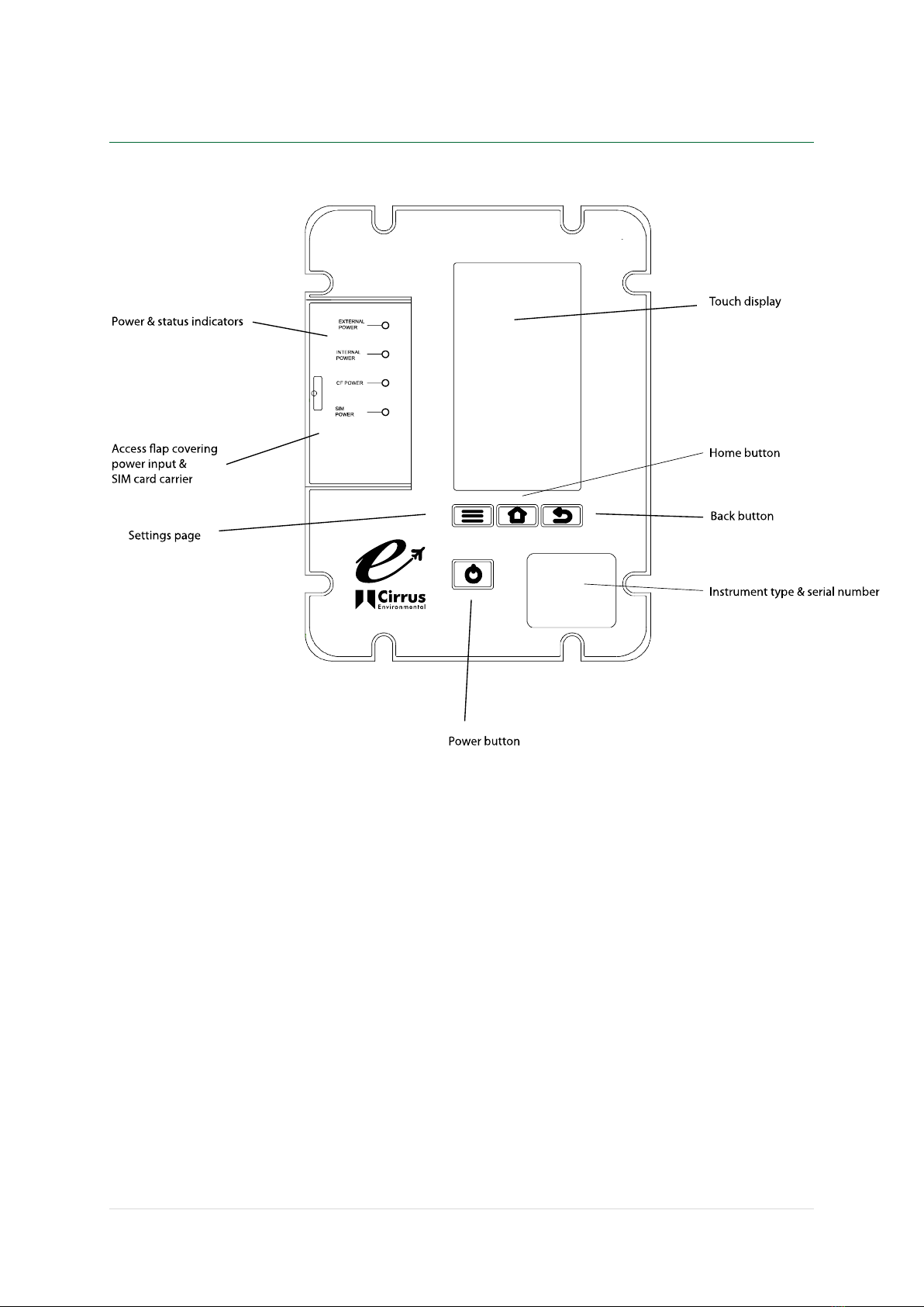
Front panel ........................................................................................... 9
Access flap .......................................................................................... 10
External Connectors................................................................................12
Getting started ........................................................................................15
The Invictus display ................................................................................... 18
Home Page .......................................................................................... 18
Live View ............................................................................................ 20
Status Page ..........................................................................................21
Settings Page........................................................................................ 24
Calibration of the Invictus ........................................................................... 27
Auto Calibration Check ............................................................................ 27
Acoustic Calibration................................................................................ 28
Operating the Invictus ................................................................................ 31
Starting & Stopping measurements .............................................................. 31
Repeat Timers & Calendar based measurements ..............................................31
Noise Event Triggers ...............................................................................31
System alarms.......................................................................................32
Notifications......................................................................................... 32
Live Audio Playback ................................................................................ 33
Downloading measurements ...................................................................... 33
Charging the Invictus battery........................................................................ 35
Checking the battery power ...................................................................... 35
Charging the internal battery packs ............................................................. 35
Data storage on the memory card .................................................................. 38
Formatting the memory card ..................................................................... 38
Memory storage size ...............................................................................38
Peripherals ............................................................................................. 40
Communications ports ............................................................................. 40
Ethernet ............................................................................................. 41
Invictus Modem, SIM Card Requirements & Installation ......................................... 43
MK:185 Outdoor Microphone .........................................................................45
Noise-Hub2 software package ....................................................................... 48
Appendix A - Specifications ..........................................................................49
Standards, Frequency & Time Weightings ...................................................... 49

Page 3
Measurements....................................................................................... 49
Physical .............................................................................................. 51
Appendix B –Invictus External Connectors ........................................................ 52
COMMS A Connector................................................................................52
COMMS B Connector................................................................................ 52
Appendix C Noise-Hub2 system requirements.....................................................53
EU Declaration of Conformity ....................................................................... 54
Regulatory Notices .................................................................................... 55
US FCC Notice....................................................................................... 55
Exposure Information to Radio Frequency Energy ............................................. 55
Warranty information................................................................................. 56
Contact information ..................................................................................57

Page 4
Introduction

Page 5
Introduction
Welcome to your Invictus Environmental Noise Monitor.
This next-generation instrument from Cirrus Environmental is powerful yet simple to use,
and is capable of a wide range of noise measurement functions as well as measuring data
from other external sources such as weather sensors.
The Invictus provides the following features:
1. IEC 61672-1:2002 Class 1 performance
2. 120dB dynamic span in a single measurement range
3. Simultaneous recording of all measurements
4. A large, full-colour touch screen display to show live data and review instrument
settings
5. Fully weather protected outdoor microphone with rain resistive windscreen, rain
protected microphone and electrostatic actuator to provide single tone self-
calibration and wide band white noise testing to test for damaged microphones
6. 32Gb memory as standard
7. Long battery life with internal power and support for external power input
8. Optional support for communications over 3G/GPRS, Wi-Fi, Ethernet, USB and
RS232
9. Optional support for external weather sensors

Page 6
Components of your Invictus
system

Page 7
Components of your Invictus system
A standard CR:247 Invictus is supplied with the following components:
•CR:247 Main Unit
•MK:185 Preamp Assembly consisting of MV:184 Pre-amp Housing and UA:182
Windshield assembly
•MM:247/5 GPS Antenna
•MM:247/6 SMA-FME Adaptor for Antenna
•CF:32G 32G Compact Flash Card (preinstalled into unit)
•CU:247/1 Mains DC Power Supply
•SP:200 Cirrus Stylus Pen
•UM:247 User Manual & Certificates of Calibration
•Noise-Hub2 Installation CD
Other items may be included with your equipment if they have been specifically ordered.
Please refer to the shipping information supplied with your Invictus unit.
If you find that any components are missing, please contact Cirrus Environmental or your
local distributor.
Warnings
The following symbol is shown where caution or attention is required to the information
given.
Please read these sections carefully. If you have any questions, please contact your Cirrus
Environmental representative.
Additional information may be provided with the Invictus User Manual.
Please read any additional information carefully.

Page 8
Unit overview

Page 9
Unit Overview
Front panel
Touch Display
•The touch display will power up after the Invictus has been switched on, when the
case is opened or when the power button is pressed after the unit it has gone to
sleep.
•The display is powered down when the case is closed to conserve power
oWhen the case is opened, the display may be off. Press the power button
once and wait for the display to start
•The display powers down after 10 minutes of no user activity.
Power Button
•If the power switch (under the Access Flap) is set to ON, pressing this button will
power up the unit or wake up the display.
•A press of a few seconds will result in a pop up menu option to shut down Invictus.
•An extended >15 second press will result in a forced shutdown of Invictus.
This is not recommended in normal operation as it will bypass file shutdown, and
possibly result in lost measurement results.

Page 10
Display navigation buttons
•Menu button selects the settings page.
•Home button selects the home page.
•Back Button selects the last viewed page.
Access flap
The Access Flap shows the status of the following:
•External Power –The LED shows when external power is connected
•Internal Power –The LED shows when the internal power is active
•CF Power –The LED shows when the Compact Flash card (CF) is powered
•SIM Power - The LED shows when the SIM card is powered
See the following section for details of the functions and connectors under the Access
Flap.
Access flap
The access flap provides environmental protection for the following user functions. Lift
the rubber cover to view the connectors and
Master power switch
•This is a physical switch to minimise power drawn from Invictus and internal power
pack when the instrument is not in use for extended periods.
•This switch also removes power from the external 12V supply on Comms B
connector.
Fast charge power input
•Connect the supplied 15V 5A DC power supply to fast charge the internal battery
packs.
•See Charging the Invictus on page 35.

Page 11
Battery charging indicators
•The LED indicators indicate charging status of the internal battery packs.
•See Charging the Invictus on page 35.
External Power LED
•This LED indicates that power has been applied to either the external
Power/Comms A connector or the fast charge port.
Internal Power LED
•This LED indicates that the unit is powered. The LED flashes to indicate that the
unit is running correctly.
•Slow flashing once every 3 seconds indicates the internal battery power is good
•Fast flashing twice per second indicates that internal battery power is low.
WARNING –Connect External Power before trying to power up the
Display if the Internal Power LED is indicating battery low.
Compact Flash LED
•This LED indicates that power is applied to the Compact Flash
SIM Power LED
•This LED indicates that power is applied to the communications module and it is
enabled.
Compact Flash
•Slot for Compact Flash Memory Card. The maximum support size is 32GB.
WARNING –take care when removing and inserting the card to ensure it
is located correctly into the guide rails.
WARNING –only remove or insert a Compact Flash card when the unit is
powered down.

Page 12
SIM card carrier for Modem option
•Slot with card holder for Modem SIM card.
WARNING –take care when removing and inserting the card to ensure it
is located correctly into the guide rails.
WARNING –only remove or insert a SIM Card when the unit is powered
down.
Note: The SIM Carrier may be different depending upon the
specification of the Invictus unit. Please see page 43 for details of the
SIM card requirements and fitting of the SIM card to the Invictus.
USB socket
•This Mini USB socket can be to connector the Invictus directly to a PC.
WARNING –avoid using USB at the same time as having a peripheral
attached to Comms A. These both share some of the same resources so
may result in lost connections or data loss.
External Connectors
The connector panel on the side of the Invictus provides access to the following functions:
RF Connector
•RF connector for Modem or Wi-Fi antenna depending on options fitted to the
Invictus.
•The connector is an FME style RF connector. Use the supplied FME to SMA adaptor
as required.

Page 13
GPS Connector
•GPS connector for the GPS sensor supplied with the Invictus.
•The connector is an FME style RF connector. Use the supplied FME to SMA adaptor
as required.
COMMS A
•Trickle charge power and COMMS A Connector (see Appendix B –Invictus External
Connectors for more information)
•7 pin connector for external power to trickle charge the batteries and power the
unit for extended periods. Only use Cirrus provided power supplies.
•Serial data interface for Cirrus peripherals (COM 0).
COMMS B
•COMMS B Connector (see Appendix B –Invictus External Connectors for more
information)
•19 way socket
•Provides a regulated 12V DC supply out for use with other external peripherals
•Serial data interface for Cirrus Peripherals (COM 4)
Microphone
•Connection for the outdoor microphone
Gland for custom options
•As standard, this connection is not used and is reserved for future use

Page 14
Getting started

Page 15
Getting started
When you receive your Invictus unit, please follow the steps 1 to 11 below before
installing or deploying the unit.
1. Assemble the instrument
Connect the Microphone to the Invictus through the
Microphone connector
Ensure that the windshield assembly is fully fitted.
See page Error! Bookmark not defined..
Connect the GPS Antenna (where provided)
Connect any communications antenna provided with
the system (where provided)
2. Charge the internal
battery
See ‘Charging the Invictus battery’ on page 35
3. Switch on the Invictus
Slide the main power switch under the flap to the
ON position.
The Invictus should power up if external power is
applied.
If the unit is running on the internal batteries, press
the power button.
The Internal Power LED should light up immediately
followed by the display
4. Enter a PIN
The display will initially show the Invictus logo
followed by a page to set the PIN.
If a PIN is required enter it twice and select
<Confirm>
If a PIN is not required, do not enter a PIN and
select <Confirm>
5. Select the operating
language
Choose the required language for the instrument
The display will default to the Home page (See page
18).
6. Check the instrument
status
Select the instrument Status (See page 21 and check
the time and date is set correctly (See page 24).

Page 16
If the time and date are not correct, adjust the
settings through the Settings page (See page 24) or
through the Noise-Hub2 software (See page 48).
7. Connect the Invictus to
the Noise-Hub2 software
over a USB connection
Using the USB connection under the Access Flap,
connect to the Noise-Hub2 software.
Connect the Invictus to a PC running the Noise-Hub2
software via a USB connection and confirm that the
measurement setup is as required.
Check the duration of the measurements
The instrument will be configured with 1 hour
measurements as default. To change the duration of
measurement, configure the settings from the Noise-
Hub2 software.
The calendar based measurements are also
configured from within Noise-Hub2.
Check that any required triggers are active and are
programmed into the instrument.
Check that any communications options are
configured correctly.
8. Calibrate the Invictus
From the Noise-Hub2 software or from the Settings
screen carryout a calibration of the Invictus system.
See ‘Calibrating the Invictus’ section.
9. Disconnect from the
Noise-Hub2 software
If the configuration is correct, disconnect the
Invictus from the Noise-Hub2 software.
10. Check remote
communications between
the Invictus and the
Noise-Hub2 software.
Before deploying the Invictus, it is recommended to
check that any remote communications are
operating correctly and that the Noise-Hub2
software can connect to and download from the
instrument
11.
If the instrument is ready to start making
measurements, go to the Home screen and press
Start Measuring (See page 18).
If repeat or calendar based timers are enabled, the
instrument will start measuring data according to
the settings.

Page 17
The Invictus display

Page 18
The Invictus display
The Invictus display contains 4 main pages:
•Home
•Live Data
•Status
•Settings
Navigation between each page is via the tabs at the top of the page or the three
navigation buttons.
Home Page
The following functions are available on the HOME page:
•Manual start/stop measuring
The button will also be available when the unit is measuring due to timers or
calendars.
Pressing this button will stop or start current measurement, but will be overridden
by any preset timers or calendars on the next schedule stop or start.
•Time history graph and number view of LAeq,1s in dB.

Page 19
a. The colour of the live view graph shows the following
i. Dark green –not measuring
ii. Light green –measuring
iii. Blue –recording audio
iv. Red –overload condition
•During an audio overload condition an ‘Overload’ message will be displayed for 5
mins
•Indication of whether the Instrument is ready and capable of measurements, for
example a Pre-Amp not fitted or a non-formatted compact flash card will prevent a
measurement.
•Indication of whether timers have been set
•Indication of which communication module has been fitted and whether it is ready
to communicate
•Indication of the power source, whether running on internal batteries or external
power
•Indication of last factory calibration date.
Other manuals for INVICTUS
1
Table of contents
Other Cirrus Measuring Instrument manuals

Cirrus
Cirrus CR:800B Series User manual

Cirrus
Cirrus CR800 series User manual

Cirrus
Cirrus Optimus+ User manual

Cirrus
Cirrus Optimus+ User manual

Cirrus
Cirrus CR:514 User manual

Cirrus
Cirrus Optimus+ Series User manual

Cirrus
Cirrus CR:262 User manual

Cirrus
Cirrus CK675 User manual

Cirrus
Cirrus CR:270 Series User manual

Cirrus
Cirrus Quantum Outdoor User manual