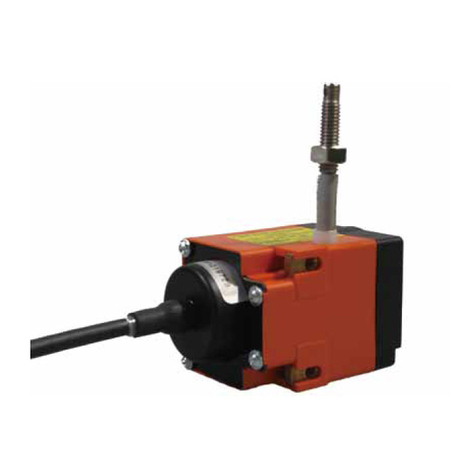
Siko ProTool SGH25 User manual

063/19
SGH25
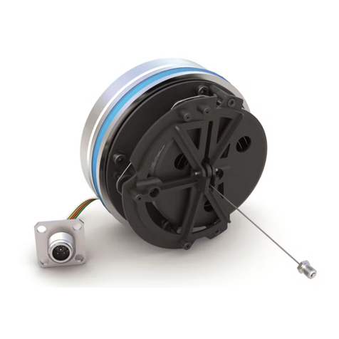
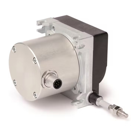
Redundant Absolute Wire-Actuated Encoder
with CANopen Interface
User Manual

General Information
SGH25 Date: 27/03/2019 Art. No. 89925 Change Status 063/19 Page 2 of 74
Table of Contents
1General Information .................................................................................................. 5
1.1 Documentation ........................................................................................................5
1.2 Definitions ..............................................................................................................5
2Intended use............................................................................................................. 5
2.1 Switching on the supply voltage.................................................................................6
2.2 Device identification.................................................................................................6
3Operation description ................................................................................................ 7
3.1 Counting direction....................................................................................................7
3.2 Calibration ..............................................................................................................7
3.3 Restore factory setting..............................................................................................7
4Communication via CAN bus (CANopen and CANopen Safety)........................................ 7
4.1 Telegram structure....................................................................................................8
4.2 Node control............................................................................................................9
4.2.1 Network Management Services (NMT) .......................................................................9
4.2.1.1 NMT Communication States ...............................................................................10
4.2.1.2 Switching between the NMT communication states...............................................11
4.2.2 Boot-Up.............................................................................................................11
4.2.3 SYNC Object .......................................................................................................11
4.3 Process Data Exchange ............................................................................................11
4.3.1 Transmission of Process Data Objects (PDO) ............................................................11
4.3.1.1 Transmit PDO (from the SGH25 to the master) .....................................................12
4.4 Parameter Data Exchange ........................................................................................13
4.4.1 Transmission of Service Data Objects (SDO).............................................................13
4.4.1.1 Accelerated request and confirmation procedure ..................................................13
4.4.1.2 Normal Request and Confirmation Procedure........................................................14
4.4.1.3 Error response in SDO exchange .........................................................................15
4.4.1.4 SDO Examples .................................................................................................16
4.5 Safety data exchange ..............................................................................................18
4.5.1 Transmission of safety-relevant data objects (SRDO) ................................................18
4.5.2 Transmission of Service Data Objects (SDO) of the Safety Parameters..........................18
4.5.3 Procedure for the first commissioning of SRDO messages ..........................................19
4.5.4 Example for calculating a checksum .......................................................................19
4.5.5 Example of changing a configuration .....................................................................20
4.6 Node monitoring ....................................................................................................20
4.6.1 Emergency service (EMCY) ....................................................................................20
4.6.2 Node Guarding....................................................................................................21
4.6.3 Heartbeat ..........................................................................................................22
4.7 Layer Setting Service (LSS) ......................................................................................22
4.7.1 State Change......................................................................................................23
4.7.1.1 Switch states of all LSS Devices (Switch state global) ...........................................23
4.7.1.2 Switch states of individual devices (Switch state global).......................................24

General Information
SGH25 Date: 27/03/2019 Art. No. 89925 Change Status 063/19 Page 3 of 74
4.7.2 Configuration .....................................................................................................24
4.7.2.1 Node ID Setting (Configure Node ID)..................................................................24
4.7.2.2 Configuration of the baud rate (Configure bit timing parameters)...........................25
4.7.2.3 Activate Baud Rate (Activate bit timing parameters) ............................................26
4.7.2.4 Store configuration..........................................................................................27
4.7.3 Request parameters .............................................................................................27
4.7.3.1 Request vendor ID ...........................................................................................27
4.7.3.2 Request product code.......................................................................................28
4.7.3.3 Request revision number...................................................................................28
4.7.3.4 Request serial number ......................................................................................28
4.7.3.5 Request Node ID..............................................................................................29
4.8 Table of Objects .....................................................................................................29
4.8.1 Object Overview..................................................................................................29
4.8.2 Object Description...............................................................................................32
4.8.2.1 1000h Device Type...........................................................................................32
4.8.2.2 1001h: Error Register .......................................................................................32
4.8.2.3 1002h: Manufacturer Status Register ..................................................................33
4.8.2.4 1003h: Pre-defined Error Field...........................................................................33
4.8.2.5 1005h: COB-ID SYNC Message ............................................................................34
4.8.2.6 1008h: Manufacturer Device Name .....................................................................34
4.8.2.7 1009h: Manufacturer Hardware Version ...............................................................34
4.8.2.8 100Ah: Manufacturer Software Version................................................................35
4.8.2.9 100Ch: Guard Time...........................................................................................35
4.8.2.10 100Dh: Life Time Factor....................................................................................35
4.8.2.11 1010h: Store Parameter....................................................................................36
4.8.2.12 1011h: Restore Parameter.................................................................................37
4.8.2.13 1014h COB ID emergency message .....................................................................39
4.8.2.14 1017h: Producer Heartbeat Time........................................................................40
4.8.2.15 1018h: Identity Object.....................................................................................40
4.8.2.16 1200h: Server SDO Parameter ............................................................................41
4.8.2.17 1301h: SRDO1 Communication Parameter ............................................................42
4.8.2.18 1302h: SRDO2 Communication Parameter ............................................................43
4.8.2.19 1381h: SRDO1 mapping parameters ....................................................................45
4.8.2.20 1382h: SRDO2 mapping parameters ....................................................................46
4.8.2.21 13FEh: Safety Configuration ..............................................................................47
4.8.2.22 13FFh: Safety configuration signature (checksum)................................................47
4.8.2.23 1800h 1. Transmit PDO Parameter ......................................................................49
4.8.2.24 1801h: 2. Transmit PDO Parameter .....................................................................50
4.8.2.25 1A00h: 1. Transmit PDO Mapping Parameter ........................................................51
4.8.2.26 1A01h: 2. Transmit PDO Mapping Parameter ........................................................52
4.8.2.27 5000h: Diagnose CAN bus error..........................................................................53
4.8.2.28 5F09h: Bus terminal.........................................................................................53
4.8.2.29 5F0Ah: Node ID and baud rate Bus CAN ..............................................................53
4.8.2.30 6000h: Operating Parameters ............................................................................54

General Information
SGH25 Date: 27/03/2019 Art. No. 89925 Change Status 063/19 Page 4 of 74
4.8.2.31 6002h: Total number of measuring steps.............................................................55
4.8.2.32 6003h: Preset value (calibration value)...............................................................55
4.8.2.33 6004h: Position value ......................................................................................55
4.8.2.34 6005h: Resolution ...........................................................................................55
4.8.2.35 600Ch: Position raw value.................................................................................56
4.8.2.36 6010h: Preset value (calibration value)...............................................................56
4.8.2.37 6020h: Position value ......................................................................................57
4.8.2.38 6030h: Speed..................................................................................................57
4.8.2.39 6031h: Speed parameters..................................................................................58
4.8.2.40 6100h: Safety configuration parameters of the position ........................................59
4.8.2.41 6101h: Safety configuration parameters of the speed ...........................................60
4.8.2.42 6102h: Safety preset value (safety calibration value)............................................61
4.8.2.43 6126h: Safety speed value ................................................................................62
4.8.2.44 6127h: Safety inverted speed value....................................................................62
4.8.2.45 6128h: Safety position value.............................................................................63
4.8.2.46 6129h: Safety inverted position value ................................................................63
4.8.2.47 61FEh: Safety application configuration..............................................................63
4.8.2.48 61FFh: Safety application configuration signature (checksum) ...............................64
4.8.2.49 6200h: Cycle Timer ..........................................................................................65
4.8.2.50 6400h: Work area (area state register)................................................................66
4.8.2.51 6401h: Work Area Low Limit..............................................................................67
4.8.2.52 6402h: Work Area High Limit ............................................................................68
4.8.2.53 6500h: Operating Status...................................................................................68
4.8.2.54 6501h: Single-turn resolution............................................................................69
4.8.2.55 6502h: Number of distinguishable revolutions .....................................................69
4.8.2.56 6503h: Alarms.................................................................................................69
4.8.2.57 6504h: Supported Alarms..................................................................................70
4.8.2.58 6505h: Warnings .............................................................................................70
4.8.2.59 6506h: Supported Warnings ..............................................................................70
4.8.2.60 6507h: Profile and Software Version...................................................................71
4.8.2.61 6508h: Operating Time.....................................................................................71
4.8.2.62 6509h: Offset value .........................................................................................71
4.8.2.63 650Ah: Module identification ............................................................................72
4.8.2.64 650Bh: Serial number.......................................................................................73
4.8.2.65 650Ch: Offset value for multi-sensor device.........................................................73
4.8.2.66 650Eh: Device functionality ..............................................................................73

General Information
SGH25 Date: 27/03/2019 Art. No. 89925 Change Status 063/19 Page 5 of 74
1General Information
1.1 Documentation
The following documents are available for this product:
Data sheet; describes the technical data, the dimensions, the pin assignments, the
accessories and the order code.
Assembly Instructions; describes the mechanical and electrical assembly with all safety-
relevant conditions and the associated technical specifications.
User Manual; for commissioning and integrating the sensor in a field bus system.
EDS file (electronic data sheet); with the help of this file, the integration and
configuration in a CANopen network by means of commercial CANopen configurators is
possible.
These documents are also available at http://www.siko-global.com/p/sgh25
1.2 Definitions
Decimal values are specified as numbers without addition (e.g., 1234) unless they are
specified in direct conjunction with binary or hexadecimal values. Then the extension d is
used (e.g., 1234d). Binary values are used with b (e.g.,1011b) and hexadecimal values with h
(e.g., 280H) following the digits.
2Intended use
The SGH25 consists of two transmitters which redundantly detect the absolute path
information. Both wire-actuated encoders can be parameterized and read via the CAN
interface using the CANopen and CANopen Safety protocols. The assessment and evaluation of
the data must be carried out in the higher-level control
The redundant version of the wire-actuated encoder SGH25 is designed for redundant position
and speed detection. The sensor can be used for applications up to Performance Level D (PLd)
in the overall system. For this purpose, a higher-level, safe encoder evaluation device is
required because the wire encoder with its internal sensor diagnosis is not able to initiate
actions itself such as the initiation of a safe state. There are increased demands on the
electrical and mechanical coupling of the wire encoder.

Intended use
SGH25 Date: 27/03/2019 Art. No. 89925 Change Status 063/19 Page 6 of 74
Sensor 2 Sensor 2
Controller / Encoder 2
CAN Transceiver
EMC-Filter
Voltage Monotoring
CAN+ CAN- CAN-GND +UB -UB
Sensor 1 Sensor 1
Controller / Encoder 1
CAN Transceiver
EMC-Filter
Voltage Monotoring
CAN+ CAN- CAN-GND +UB -UB
ST MT
N S N S
Fig. 1: Block wiring diagram
2.1 Switching on the supply voltage
The SGH25 initializes after it is switched on. The configuration parameters are loaded from
the nonvolatile memory into the main memory of the controller.
As long as no changes have been made to the sensor, the sensor works with its default values.
If parameters have been changed, the sensor works with the changed data. If these are also
to be used after a power off/on, they must be stored.
Upon completion of the initialization procedure, a special NMT command is sent, the boot-up
message, to notify the system of its existence. The SGH25 is then in pre-operational mode. In
this state, the encoder can be parameterized according to the requirements of the application
via SDO commands. This concerns both the configuration parameters of the sensor system and
the way in which it makes its position values available to the system (asynchronous or
synchronous data transmission).
2.2 Device identification
To ensure safe operation, the following parameters should be read and verified with a safety
encoder before each parameterization and commissioning.
1000h Device Type
1018h: Identity Object Subindex 01h Vendor-ID
1018h: Identity Object Subindex 02h Product Code
1018h: Identity Object Subindex 03h Revision Number
1018h: Identity Object Subindex 04h Serial Number

Operation description
SGH25 Date: 27/03/2019 Art. No. 89925 Change Status 063/19 Page 7 of 74
650Eh: Device functionality
3Operation description
3.1 Counting direction
The encoder supplies increasing position values. This property can be changed via the object
6000h: Operating Parameters.
3.2 Calibration
Due to the absolute measuring system, calibration is only required once during commissioning
and can be performed at any point. As a result, the Gerber zero point can be adjusted with the
mechanical zero point of the system. During calibration, the calibration value is used to
calculate the position value. The resulting offset value is output in object 6509h: Offset value.
In the case of calibration, the following applies:
Position value = 0 + calibration value
3.3 Restore factory setting
To restore the delivery state of the device, the following option exists:
Access
Coding
The following are set to the factory
setting
CANopen (cf.
object 1011h:
Restore Parameter)
1011h
"load"
Subindex 1
All parameters
Subindex 2
Only bus parameters
Subindex 3
Only CiA 406 parameters
Subindex 4
Only manufacturer-specific parameters
Table 1: Access factory settings
4Communication via CAN bus (CANopen and CANopen Safety)
The basis for the SGH25 is the CANopen communication profile CiA 301 V4.2, the device
profile for encoders CiA 406 V4.0.5 as well as the layer setting service (LSS) CiA 305 V3.0.0.
The CANopen Safety Protocol EN50325-5 is also implemented for safety-relevant applications.
Safety-relevant and non-safety-relevant applications can be operated on a CAN bus.
The SGH25 supports device class C2. The details necessary for understanding safety-relevant
operation are provided in this documentation. If you require more detailed information, we
recommend the relevant specialist literature on CAN, CANopen and CANopen Safety.

Communication via CAN bus (CANopen and CANopen Safety)
SGH25 Date: 27/03/2019 Art. No. 89925 Change Status 063/19 Page 8 of 74
4.1 Telegram structure
The data telegram of a CAN message consists of the following fields:
SOF
Identifier (COB ID)
Control
field
Data field (a maximum of 8
bytes)
CRC
ACK/EOF
SOF:
(Start of Frame) Start bit of the telegram
Identifier (COB ID):
All bus participants use the identifier to check whether the message is relevant to them.
The identifier sets the priority of the message. The lower the value of the identifier, the
higher the priority of the message. As a result, important messages are preferably
transmitted via the bus.
The identifier field contains the identifier as well as bits for identifying the length of the
identifier (11 or 29 bits). In addition, the identifier defines the device address, the channel
selection and the data direction.
Consequently, the 11-bit identifier (COB identifier) is composed of a 4-bit function code and a
7-bit node number:
Bit no.
10
9
8
7
6
5
4
3
2
1
0
Type
Function code
Node number (Node ID)
Assignment
x
x
x
x
0
0
x
x
x
x
X
The following function codes are defined in the "Pre-Defined Connection Set" (only those
function codes that are used in this device are shown):
Object
Function code
Resulting COB ID
Object
Page
Network Management
(NMT)
0000b
0
-
9
SYNC message
0001b
128d (80h)
1005h
34
Emergency message
0001b
128d (80h) + Node ID
1014h
39
TPD01
0011b
384d (180h) + Node ID
1800h
42
TPD02
0101b
640d (280h) + Node ID
1801h
50
SDO (tx)
1011b
1408d (580h) + Node ID
1200h
41
SDO (rx)
1100b
1536d (600h) + Node ID
1200h
41
Heartbeat message
1110b
1792d (700h) + Node ID
-
22
Node guard message
1110b
1792d (700h) + Node ID
-
21
LSS (tx)
-
2021d (7E4h)
-
22
LSS (rx)
-
2020d (7E5h)
-
22
SRDO1 COB ID1
-
Configure Node ID
1301h
18
SRDO1 COB ID2
-
100h + 2*Node ID
1301h
18
SRDO2 COB ID1
-
10Fh + 2*Node ID
1302h
18
SRDO2 COB D2
-
110h + 2*Node ID
1302h
18
Table 2: Overview of COB Identifiers

Communication via CAN bus (CANopen and CANopen Safety)
SGH25 Date: 27/03/2019 Art. No. 89925 Change Status 063/19 Page 9 of 74
Changes to COB IDs are only possible in the PRE-OPERATIONAL NMT state. Via bit 31 = 1b, the
COB ID must first be invalidated before it can be changed and reactivated.
An exception is the COB ID of the sync object. Bit 30 = 0b must be set there to change the
COB ID. Since bit 30 cannot be set to 1b in the device, the COB ID could be changed at any
time.
The node number (Node ID) (cf. Object 5F0Ah: Node ID and baud rate Bus CAN) is assigned
once in each bus system from the master to the SGH25 during the configuration. The node
numbers are in the range from 1 to 127. Node ID = 0 is reserved and may not be used.
The transfer of a newly set node number takes place only at a renewed initialization (cf.
Chapter 4.2.1).
In the case of the wire-actuated encoder SGH25, an encoder with the node ID 1 (1h) and the
redundant encoder with the node ID 2 (2h) are delivered ex works.
Control field:
Contains bit-by-bit information about the number of user data and decides whether it is a
data frame or remote transmission request (RTR) frame.
Data field:
Contains up to 8 bytes of user data. Depending on the channel selection, the user data has
different meanings.
CRC:
Contains bits for error detection.
ACK/EOF:
The ACK/EOF field contains telegram confirmation bits as well as bits to identify the telegram
end.
The exact description of the telegram can be found in the relevant CAN literature. In the
following telegram descriptions, only the identifier (COB ID) and the data field are discussed
for the sake of simplicity.
4.2 Node control
4.2.1 Network Management Services (NMT)
The master uses the NMT service to configure, manage and monitor network nodes. The device
is always in one of the four communication states: "INITIALIZATION", "PRE-OPERATIONAL",
"OPERATIONAL" or "STOPPED" (cf. Fig. 1)

Communication via CAN bus (CANopen and CANopen Safety)
SGH25 Date: 27/03/2019 Art. No. 89925 Change Status 063/19 Page 10 of 74
Power on oder Software Reset
Initialisation
CAN-Kommunikation
BootUp Message
1
2
2
3
3
4
4
4
1
Re-Initialisierung
CAN-Karte
5
55
Init
Fig. 1: NMT Status Diagram
4.2.1.1 NMT Communication States
NMT INITIALIZATION State
In this state, the device is not involved in what is happening on the bus. All hardware and
software components are initialized. This state is reached after the device is switched on or
after receiving the command code 81h ("Reset Node") of its own or the global address. After
receiving the command code 82h ("Reset Communication"), the display is also in the
initialization state. However, only the hardware and software are reinitialized that are related
to the CAN communication. The device automatically signals the completion of the
initialization with a boot-up message. As soon as the boot-up message has been sent
successfully, the device is in the "PRE-OPERATIONAL" state.
NMT PRE-OPERATIONAL State
Parameterization data (SDO) can be exchanged in Pre-Operational mode. However, no process
data (PDO) are transmitted.
NMT OPERATIONAL State
The exchange of process data is also released. COB ID and Transmit PDO Mapping parameters
cannot be changed in this state.
NMT STOPPED State
With the exception of Heartbeat and Node Guarding, communication is stopped. Only NMT
communication is possible.

Communication via CAN bus (CANopen and CANopen Safety)
SGH25 Date: 27/03/2019 Art. No. 89925 Change Status 063/19 Page 11 of 74
4.2.1.2 Switching between the NMT communication states
To switch between the communication states, telegrams with the following structure are used:
State Change
Transitio
n into
Fig. 1
COB
ID
Comm
and
Node
ID
From
To
PRE-
OPERATIONAL/STOPPED
OPERATIONAL
1d
0h
01h
x
OPERATIONAL/PRE-
OPERATIONAL
STOPPED
2d
0h
02h
x
OPERATIONAL/STOPPED
PRE-OPERATIONAL
3d
0h
80h
x
OPERATIONAL/ PRE-
OPERATIONAL/STOPPED
INITIALIZATION
(Reset Node)
5d
0h
81h
x
OPERATIONAL/ PRE-
OPERATIONAL/STOPPED
INITIALIZATION
(Reset Communication)
4d
0h
82h
x
Table 3: Switching between communication states
If x = 0h is transmitted as Node ID, then the message is intended for all bus subscribers.
4.2.2 Boot-Up
The COB ID of the boot-up message consists of 700h and the Node ID. The NMT state
"initialization" is output as data content.
COB ID
Byte 0
700h + Node-ID
00h
Table 4: Boot-up message
4.2.3 SYNC Object
CANopen makes it possible to interrogate inputs and set outputs simultaneously. A
synchronization message serves for this (SYNC), which is a high priority CAN message. The
identifier of the sync object can be set via the object 1005h (cf. 1005h: COB-ID SYNC
Message).
4.3 Process Data Exchange
4.3.1 Transmission of Process Data Objects (PDO)
Process Data Objects (PDO) are used for a fast exchange of process data. A maximum of 8
bytes of user data can be transferred in a PDO. The SGH25 supports the transmit PDO services
TPDO1 and TPDO2 according to CiA 301 and CiA 406.

Communication via CAN bus (CANopen and CANopen Safety)
SGH25 Date: 27/03/2019 Art. No. 89925 Change Status 063/19 Page 12 of 74
4.3.1.1 Transmit PDO (from the SGH25 to the master)
A PDO transmission from the display to the bus master (TPDO) can be initiated by various
events:
Asynchronously controlled by internal device timer
Synchronously in response to a SYNC message
In response to an RTR message
TPDO1 and TPDO2 are formed from the position value and the speed value. The transmission
behavior of TPDO1 is defined by the objects 1800h, 1A00h and 6200h and is assigned to
asynchronous transmission. The TPDO2 is defined via the objects 1801h and 1A01h and serves
for synchronous transmission. The assignment is set as a default and cannot be changed.
The messages are structured as follows:
COB ID
User Data in Binary Code
Byte 0
(LSB)
Byte 1
Byte 2
Byte 3
MSB
Byte 4
(LSB)
Byte 5
MSB
TPDO1
Configure Node
ID
Position value
Speed value
TPDO2
280h + Node ID
Table 5: TPDO message
Asynchronous Data Transmission (TPDO1)
If a TPDO1 is to be sent cyclically, the cycle time in milliseconds must be entered in the
object 1800h, subindex 05h. If the value 0 ms is written, TPDO1 is not sent. The function is
switched off. The minimum value to be set is 1h (= 1 ms). Alternatively, the value can also be
written in the internally linked object 6200h.
Synchronous data transmission (TPDO2)
Upon delivery, the device responds to each received SYNC message with the output of the
TPDO2 message. In object 1801h, sub-index 02h, 1h is entered for synchronous transmission.
If a value n is entered between 1d and 240d (= F0h), the device responds to every nth SYNC
message.
RTR
Requests can be sent via RTR (cf. Chapter 4.1 Control Field) to TPDO1 and TDPO2.

Communication via CAN bus (CANopen and CANopen Safety)
SGH25 Date: 27/03/2019 Art. No. 89925 Change Status 063/19 Page 13 of 74
4.4 Parameter Data Exchange
4.4.1 Transmission of Service Data Objects (SDO)
Service data objects are mainly used for device configuration via the object directory. SDOs
are supported in the expedited request/response ("accelerated request and confirmation
procedure") and in the normal request/response.
The identifier is set to 11 bits and cannot be changed.
Two different SDO services are available:
SDO (rx) (Master SGH25): 600h + Node ID
SDO (tx) (SGH25 Master): 580h + Node ID
These SDO identifiers cannot be changed!
4.4.1.1 Accelerated request and confirmation procedure
Except for the reading of the object 1008h: Manufacturer Device Name, all SDOs are
exchanged between two parties in the "expedited request/response" procedure. The user data
is already delivered with the initialization message.
These SDO messages have the following structure:
COB ID
User data in binary code
Byte 0
read /
write
Byte 1
LSB
Byte 2
MSB
Byte 3
Byte 4
LSB
Byte 5
Byte 6
Byte 7
MSB
SDO rx/tx
+ Node ID
Command
byte
Index
Subindex
User data (parameters)
Command Byte, Byte 0:
The command byte determines the type of access and the number of valid data bytes. For
SGH25, the following command bytes are valid:
Command Byte
Type
Function
Write Request
23h
SDO (rx), Initiate Download
Request, expedited
Send parameter to slave
(all 4 data bytes valid)
Write Request
2Bh
SDO (rx), Initiate Download
Request, expedited
Send parameter to slave
(2 bytes of 4 data bytes valid)
Write Request
2Fh
SDO (rx), Initiate Download
Request, expedited
Send parameter to slave
(1 byte of 4 data bytes valid)
Write Response
60h
SDO (tx), Initiate Download
Response
Confirmation of data transfer to
the master
Read Request
40h
SDO (rx), Initiate Upload
Request
Request parameters of the slave
Read Response
43h
SDO (tx), Initiate Upload
Response, expedited
Report parameters to Master
(all 4 data bytes valid)

Communication via CAN bus (CANopen and CANopen Safety)
SGH25 Date: 27/03/2019 Art. No. 89925 Change Status 063/19 Page 14 of 74
Command Byte
Type
Function
Read Response
4Bh
SDO (tx), Initiate Upload
Response, expedited
Report parameters to Master
(2 bytes of 4 data bytes valid)
Read Response
4Fh
SDO (tx), Initiate Upload
Response, expedited
Report parameters to Master
(1 byte of 4 data bytes valid)
Error Response
80h
SDO (tx), Abort Domain
Transfer
Slave reports error code to master
Table 6: Command encoding
Index, Bytes 1 and 2:
The index (object number) is entered in Intel data format in user data byte 2 (low byte) and
user data byte 3 (high byte). The index of the object to be parameterized is entered there.
Subindex, Byte 3:
For objects that are executed as an array, the subindex indicates the number of the field.
User Data (Parameters), Bytes 4-7:
In the user data, the value of the parameter is entered in left-aligned Intel representation.
Byte 4 = Low-Byte ... Byte 7 = High-Byte
4.4.1.2 Normal Request and Confirmation Procedure
If more than 4 bytes of service data have to be transmitted, the data is exchanged between
two participants using the “normal request/response procedure”. This procedure is also
initiated by an initialization message, and the actual user data are then transmitted in the
following segment messages.
With the SGH25, this is only the case when the object 1008h: Manufacturer Device Name is
read.
The initialization message has the following structure:
COB ID
User data in binary code
Byte 0
read /
write
Byte 1
LSB
Byte 2
MSB
Byte 3
Byte 4
LSB
Byte 5
Byte 6
Byte 7
MSB
SDO rx/tx
+ Node ID
Command
byte
Index
Subindex
User data (number of user data)
The segment message has the following structure:
COB ID
User data in binary code
Byte 0
read /
write
Byte 1
LSB
Byte 2
Byte 3
Byte 4
Byte 5
Byte 6
Byte 7
MSB
SDO rx/tx
+ Node ID
Command
byte
User Data

Communication via CAN bus (CANopen and CANopen Safety)
SGH25 Date: 27/03/2019 Art. No. 89925 Change Status 063/19 Page 15 of 74
Initialization and segment message: Command Byte, Byte 0:
The command byte determines the type of access and the number of valid data bytes. The
following command bytes are valid for the encoder:
Command Byte
Type
Function
Read Request
40h
SDO (rx), Normal Initiate
Upload Request
Request parameter from slave
(number of bytes to be
transmitted)
Read Request
60h
SDO (rx), Normal Segment
Upload Request
Request parameters from slave
(user data)
Read Response
41h
SDO (tx), Normal Initiate
Upload Response
Report parameter to master
(number of bytes to be
transferred)
Read Response
03h
SDO (tx), Normal Segment
Upload Response
Report parameters to Master (user
data)
Error Response
80h
SDO (tx), Abort Domain
Transfer
Slave reports error code to master
Table 7: Command encoding
Initialization Message: Index, Bytes 1 and 2:
The index (object number) is entered in Intel data format in user data byte 2 (low byte) and
user data byte 3 (high byte). The index of the object to be parameterized is entered there.
Initialization message: Subindex, Byte 3:
For objects that are executed as an array, the subindex indicates the number of the field.
Initialization message: User Data (Parameters), Bytes 4-7:
In the service data area, the value of the parameter is entered in left-aligned Intel
representation. Byte 4 = Low-Byte ... Byte 7 = High-Byte
Segment message: User data (parameters), bytes 1-7:
In the user data area, the value of the parameter is entered in left-aligned Intel
representation. Byte 1 = Low-Byte ... Byte 7 = High-Byte
4.4.1.3 Error response in SDO exchange
If the access is invalid, an error message (abort) is returned to the master.
The error codes are described in the CANopen profile (CiA 301) or in the encoder profile (CiA
406). The following table shows the error codes used:
Error Code
Description
05030000h
Toggle bit in normal transfer of request/response unequal.
06010000h
Incorrect access to an object.
06010001h
Read access to write-only.
06010002h
Write access to read-only.

Communication via CAN bus (CANopen and CANopen Safety)
SGH25 Date: 27/03/2019 Art. No. 89925 Change Status 063/19 Page 16 of 74
Error Code
Description
06020000h
Object does not exist in the object dictionary.
06090011h
Subindex does not exist.
06090030h
Value range of the selected parameter incorrect.
08000020h
Parameters cannot be transferred or saved to the application.
08000022h
Parameters cannot be transferred or saved to the application due to the
current state of the device.
08000024h
No data available
Table 8: Error codes
4.4.1.4 SDO Examples
Example of Reading SDO Parameters with Accelerated Request and Confirmation
Procedure:
From the slave with device address 1h, the calibration value stored in object 6010h subindex
01h of the object directory is to be read.
Calculation of the identifier: 600h + Node ID = 600h +1h = 601h
Command: 40h
Index: 6010h
Subindex: 01h
The current value is 510d = 01FEh
Request from master to slave with Node ID 1h:
COB
ID
User Data
Command
Index L
Index H
Subindex
Data
0
Data
1
Data
2
Data
3
601h
40h
10h
60h
01h
x
x
x
x
Slaves response to the request:
Calculation of the identifier: 580h + Node ID = 581h
COB
ID
User Data
Command
Index
LB
Index
HB
Subindex
Data
0
Data
1
Data
2
Data
3
581h
43h
(4 bytes
valid)
10h
60h
01h
FEh
01h
00h
00h
Example of Writing SDO Parameters with Accelerated Request and Confirmation
Procedure:
In the slave with device address 1h, the calibration value, which is stored with 2 bytes in
object 6200h of the object directory, is to be changed.
Calculation of the identifier: 600h + Node ID = 600h + 1h = 601h
Command: 2 bytes are to be written: 2Bh
Index: 6200h

Communication via CAN bus (CANopen and CANopen Safety)
SGH25 Date: 27/03/2019 Art. No. 89925 Change Status 063/19 Page 17 of 74
Subindex: 00h
The new value should be 4500d = 1194h
Write a value from the master to the slave with Node ID 1h:
COB
ID
User Data
Command
Index L
Index H
Subindex
Data
0
Data
1
Data
2
Data
3
601h
2Bh
(2 bytes
valid)
00h
62h
00h
94h
11h
00h
00h
Response of the slave to the command:
Calculation of the identifier: 580h + Node ID = 580h + 1h = 581h
COB
ID
User Data
Command
Index L
Index H
Subindex
Data
0
Data
1
Data
2
Data
3
581h
60h
00h
62h
00h
00h
00h
00h
00h
Example of Reading SDO Parameters with Normal Request and Confirmation Procedure:
From SGH25 with device address 1h, the manufacturer device name stored in object 1008h of
the object directory is to be read.
Calculation of the identifier: 600h + Node ID = 600h +1h = 601h
Command: 40h
Index: 1008h
Subindex 00h
First request (initialization) from master to slave with Node ID 1h:
COB
ID
User Data
Command
Index L
Index H
Subindex
Data
0
Data
1
Data
2
Data
3
601h
40h
08h
10h
00h
x
x
x
x
Slaves response to the request:
Calculation of the identifier: 580h + Node ID = 581h
COB
ID
User Data
Command
Index
LB
Index
HB
Subindex
Data
0
Data
1
Data
2
Data
3
581h
41h
08h
10h
00h
05h
00h
00h
00h
Expected number of user data bytes: 5
Second request from master to slave with Node ID 1h:
COB
ID
User Data
Command
Index L
Index H
Subindex
Data
0
Data
1
Data
2
Data
3
601h
60h
08h
10h
00h
x
x
x
x

Communication via CAN bus (CANopen and CANopen Safety)
SGH25 Date: 27/03/2019 Art. No. 89925 Change Status 063/19 Page 18 of 74
Slaves response to the request:
COB
ID
User Data
Command
Data 0
Data 1
Data 2
Data 3
Data 4
Data 5
Data 6
581h
03h
53h
("S")
47h
("G")
48h
("H")
32 h
("2")
35h
("5")
00h
-
00h
-
4.5 Safety data exchange
4.5.1 Transmission of safety-relevant data objects (SRDO)
Safety-relevant data objects (SRDO) are used for the cyclic exchange of secure data in the
NMT state Operational. An SRDO always consists of 2 messages with different COB ID and data
inverted bit by bit. A maximum of 8 bytes of user data can be transmitted in a SRDO. The
SGH25 supports the Safety Transmit services SRDO1 for the position value (4 bytes) and SRDO2
for the speed (2 bytes) according to EN50325-5. The transmission behavior of SRDO1 is
determined via the objects 1301h, 1381h, 6100h and 6102h. The SRDO is set via the objects
1302h, 1382h, 6101h and 6102h. The mapping is set fixed and cannot be changed.
COB ID
User Data
Byte 0
(LSB)
Byte 1
Byte 2
Byte 3
MSB
SRDO1 COB ID1
000000FFh + 2*Node ID
Position value
SRDO1 COB ID2
00000100h + 2*Node ID
Bit-inverted position value
Table 9: SRDO1 message
COB ID
User Data
Byte 0
(LSB)
Byte 1
(MSB)
SRDO2 COB ID1
0000010Fh + 2*Node ID
Speed value
SRDO2 COB D2
00000110h + 2*Node ID
Bit-inverted speed
value
Table 10: SRDO2 message
4.5.2 Transmission of Service Data Objects (SDO) of the Safety Parameters
All safety-related service data objects for the device configuration are addressed in the
expedited request/response.
All changes of safety-related service data objects are monitored via a checksum CRC-16-CCITT
and can only be carried out in the NMT state pre-operational. The polynomial is: g(x) =
x16+x12+x5+1.

Communication via CAN bus (CANopen and CANopen Safety)
SGH25 Date: 27/03/2019 Art. No. 89925 Change Status 063/19 Page 19 of 74
Procedure for changing the configuration data in the objects 1301h, 1302h, 6100h, 6101h
and 6102h:
Change values
Enter a new valid checksum (sub-index of the corresponding object 13FFh or object
61FFh).
Set the corresponding configuration to valid via object 13FEh or 61FEh.
4.5.3 Procedure for the first commissioning of SRDO messages
The following steps are necessary for the exchange of safety data via SRDO messages for
commissioning:
Device must be in NMT state "PRE-OPERATIONAL"
Configuration parameters for SRDO1 (cf. chapter 4.8.2.17), SRDO2 (cf. chapter 4.8.2.18),
position (cf. chapter 4.8.2.40) and speed (cf. chapter 4.8.2.41) must be adjusted
Calculate checksums (cf. 4.8.2.22 chapter and cf. 4.8.2.48 chapter)
Set configurations to valid (cf. chapters 4.8.2.21 and 4.8.2.47)
Save configurations if necessary (cf. chapter 4.8.2.11)
Switch to the NMT state "OPERATIONAL" (cf. chapter 4.2.1.2)
Now the SRDO messages are transmitted according to the configuration parameters.
4.5.4 Example for calculating a checksum
In the following example, the checksum CRC-16-CCITT (polynomial 1021h) for SRDO2 is to be
calculated. The checksum is calculated byte-by-byte and begins with the low byte over the
content of the two objects 1302h and 1382h.
Object
Subindex
Name
Size
Data
1302h
SRDO2 Communication Parameter
01h
Information direction
1 byte
01h
02h
Refresh time
2 byte
0019h
03h
tx: reserved
rx: SRVT
1 byte
14h
05h
COB ID 1
4 byte
00000111h
06h
COB ID 2
4 byte
00000112h
1382h
SRDO2 mapping parameters
00h
Highest sub-index
1 byte
02h
01h
Subindex
1 byte
01h
01h
Speed value
4 byte
61260110h
02h
Subindex
1 byte
02h
02h
Inverted speed value
4 byte
61270110h
The following data bytes are used to calculate the checksum:

Communication via CAN bus (CANopen and CANopen Safety)
SGH25 Date: 27/03/2019 Art. No. 89925 Change Status 063/19 Page 20 of 74
01h 19h 00h 14h 11h 01h 00h 00h 12h 01h 00h 00h 02h 01h 10h 01h 26h 61h 02h 10h 01h
27h 61h
Checksum = B5BAh
4.5.5 Example of changing a configuration
In the following example, the information direction for SRDO2 is to be changed from valid to
not valid and the configuration of SRDO1 is to be retained.
Change direction of information:
COB ID
User Data
Command
Index
L
Index
H
Subindex
Data 0
Data 1
Data 2
Data 3
600h +
Node ID
2Fh
02h
13h
01h
00h
-
-
-
The default value 0000h is entered for the checksum. As a result, both checksums must be
specified in the event of a change even if only one configuration is changed.
COB ID
User Data
Command
Index
L
Index
H
Subindex
Data 0
Data 1
Data 2
Data 3
600h +
Node ID
2Bh
FFh
13h
01h
01h
02h
-
-
600h +
Node ID
2Bh
FFh
13h
02h
5Ah
08h
-
-
Activate the configuration for SRDO1 and SRDO2. During the activation, the configuration is
monitored with the aid of the checksum in object 13FFh subindex 01h and 02h.
Configurations can only be activated with the correct checksums.
COB ID
User Data
Command
Index
L
Index
H
Subindex
Data 0
Data 1
Data 2
Data 3
600h +
Node ID
2Fh
FEh
13h
00h
A5h
-
-
-
4.6 Node monitoring
4.6.1 Emergency service (EMCY)
The state of the bus participant is transmitted in the event of a fault via high-priority
emergency messages. These messages have a data length of 8 bytes and contain error
information.
The emergency message is transmitted as soon as a sensor or communication error has
occurred or is rectified. The cause of the fault is stored in the fault buffer (cf Object 1003h:
Pre-defined Error Field). An emergency object is only sent once per error event. If a cause of
Other manuals for ProTool SGH25
4
Table of contents
Other Siko Media Converter manuals