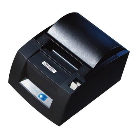
iDP3221 Service Manual
CITIZEN
CONTENTS
1. HANDLING AND MAINTENANCE OF PRINTER............................................................................................1
2. SPECIFICATIONS................................................................................................................................................2
2.1 Basic Specifications .........................................................................................................................................2
3. MECHANISMS AND OPERATING PRINCIPLES.............................................................................................3
3.1 Power Transmission and Paper Feed Mechanism ..............................................................................................3
3.2 Platen Roller Attaching/Detaching Mechanism.................................................................................................4
3.3 Sensor Mechanism...........................................................................................................................................4
3.3.1 Paper Sensor .........................................................................................................................................4
3.3.2 Paper Near-end Sensor ..........................................................................................................................5
3.4 Print Head Mechanism.....................................................................................................................................5
3.4.1 Drive Control Overview........................................................................................................................5
3.4.2 Print Data and Print Positions................................................................................................................6
4. DISASSEMBLY AND REASSEMBLY.................................................................................................................7
4.1 Disassembly Procedure ....................................................................................................................................7
4.2 Reassembly Procedure ...................................................................................................................................14
5. TROUBLESHOOTING.......................................................................................................................................15
5.1 Troubleshooting Procedure.............................................................................................................................15
5.2 Troubleshooting Guide...................................................................................................................................15
6. SERVICE PARTS LIST.......................................................................................................................................19
6.1 Parts List for Mechanism................................................................................................................................19
6.2 Disassembly Drawing.....................................................................................................................................21
6.3 Parts List for Control PCB Assy.....................................................................................................................23
6.4 Parts Layout Drawing.....................................................................................................................................26
6.4.1 Control PCB Assy 3221-01 (Serial Interface D-sub 25)........................................................................26
6.4.2 Control PCB Assy 3221-02 (Parallel Interface)....................................................................................28
7. DRAWING...........................................................................................................................................................30
7.1 Block Diagram...............................................................................................................................................31
7.2 Circuit Diagram .............................................................................................................................................32
7.2.1 Control PCB Assy 3221-01 (Serial Interface D-sub 25)........................................................................32
7.2.2 Control PCB Assy 3221-02 (Parallel Interface)....................................................................................33
8. OUTER DIMENSION.........................................................................................................................................34
* For the auto cutter unit (ACS-231), see the separate Service Manual.
