manuals.online logo
Brands
  1. Home
  2. •
  3. Brands
  4. •
  5. CLA-VAL
  6. •
  7. Control Unit
  8. •
  9. CLA-VAL 50B-4KG1 Owner's manual

CLA-VAL 50B-4KG1 Owner's manual

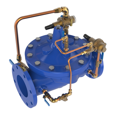
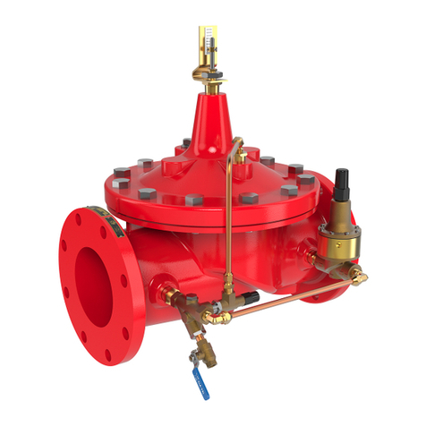
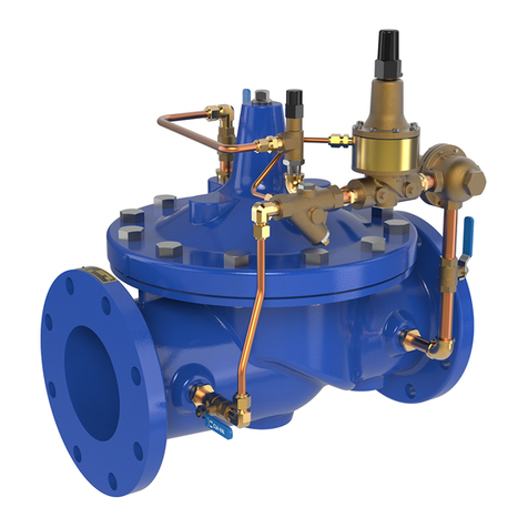
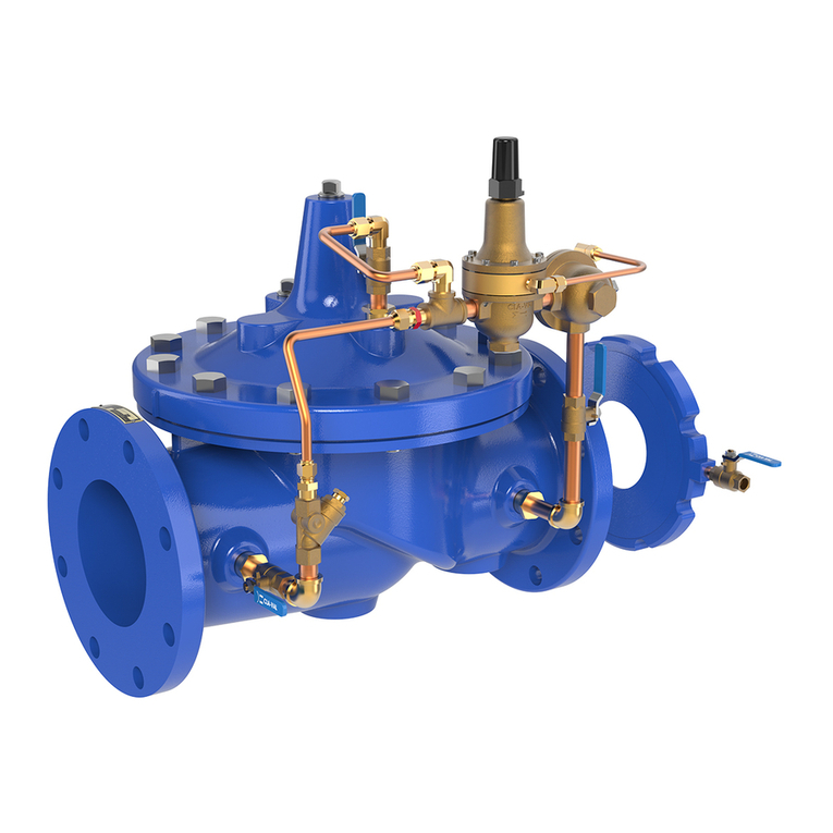
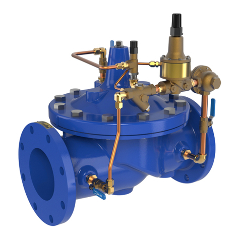
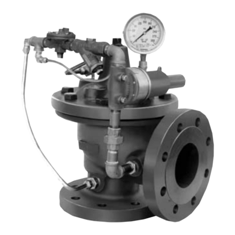
The Cla-Val Model 50B-4KG1 Globe /2050B-4KG1 Angle
Pressure Relief Valve is designed specifically to automatically
relieve excess pressure in fire protection pumping systems. Pilot
controlled, it maintains constant system pressure at the pump dis-
charge within very close limits as demands change.
The Fire Pump Pressure Relief Valve shall modulate to relieve
excess pressure in a fire protection system. It shall maintain con-
stant pressure in the system regardless of demand changes. It
shall be pilot controlled and back pressure shall not affect its set
point. It shall be actuated by line pressure through a pilot control
system and open fast in order to maintain steady system pressure
as system demand decreases. It shall close gradually to control
surges and shall re-seat drip-tight within 5% of its pressure setting.
INSTALLATION
1. Allow sufficient room around the valve assembly to make
adjustments and for servicing.
2. lt is recommended that gate or block valves be installed to
facilitate isolating valve for preventative maintenance. When used
as a surge control or pressure relief valve where valve outlet dis-
charge is to atmosphere, then a gate or block valve is needed at
valve inlet. When used as a back pressure sustaining control
valve where valve outlet is connected to pressurized downstream
system, then gate or block valves are needed at valve inlet and
outlet.
NOTE: BEFORE THE VALVE IS INSTALLED, PIPE LINES
SHOULD BE FLUSHED OF ALL FOREIGN MATTER.
3. Place valve in line with flow through valve in direction indicated
on inlet plate or flow arrows. Check all fittings and hardware for
proper makeup and verify that no apparent damage is evident.
4. Cla-Val Valves operate with maximum efficiency when mounted
in horizontal piping with the cover UP; however, other positions are
acceptable. Due to size and weight of cover and internal components
on six inch and larger valves, installation with the cover up is
advisable. This makes periodic inspection of internal parts readily
accessible.
5. Caution must be taken in the installation of this valve to insure that
galvanic and/or electrolytic action does not take place. The proper use
of dielectric fittings and gaskets are required in all systems using dis-
similar metals.
OPERATION AND START-UP
1. Prior to pressurizing the valve assembly make sure the nec-
essary gauges to measure pressure in the system, are installed
as required by the system engineer.
CAUTION: During start-up and test a large volume of water
may be discharged downstream. Check that the downstream
venting is adequate to prevent damage to personnel and equip-
ment. All pilot adjustments should be made slowly in small
increments. If the main valve closes too rapidly it may cause
surging in upstream piping.
2. Remove cap from CRL-60 then loosen adjusting screw coun-
terclockwise. This will allow the valve to open at low pressure
relieving the full flow of the fire pump. Bleed all air from the valve
at this time by carefully loosening the cover plug and tube fittings
at the high points. Slowly turn the adjusting screw clockwise on
the CRL-60 while watching the gauge between the valve and the
pump until you reach the desired set-point. Tighten the jam nut on
the CRL-60 and replace the cap. DO NOT USE THE GAUGE
PROVIDED ON THE VALVE TO SET THE VALVE. IT IS ONLY
THERE TO INDICATE PRESSURE IN THE COVER.
MAINTENANCE
1. Cla-Val Valves and Controls require no lubrication or packing
and a minimum of maintenance. However, a periodic inspection
schedule should be established to determine how the fluid is
affecting the efficiency of the valve assembly. Minimum of once
per year.
2. Repair and maintenance procedures of the Hytrol Main Valve
and control components are included in a more detailed Tech
Manual. It can be downloaded from our web site (www.cla-val.com)
or obtained by contacting a Cla-Val Regional Sales Office.
3. When ordering parts always refer to the catalog number
and stock number on the valve nameplate.
Pressure Relief Valve
50B-4KG1/2050B-4KG1
MODEL
INSTALLATION / OPERATION / MAINTENANCE
SYMPTOM PROBABLE CAUSE REMEDY
Main valve
won’t open
Inlet pressure is below set-
ting of pilot valve.
Reset pilot valve. If
change is from tam-
pering, seal cap with
wire and lead seal.
Pilot valve is stuck closed:
Mineral deposit or foreign
material between disc retain-
er and stem guide.
Disassemble control
and clean.
Water is com-
ing out of vent
hole in cover
Pilot valve diaphragm is rup-
tured or diaphragm nut is
loose.
Disassemble and
replace diaphragm.
Tighten nut.
Main valve is
stuck closed
Mineral build-up on stem.
Stem damaged.
Disassemble main
valve, clean parts
and/or replace
damaged part.
Main valve
won’t close
Inlet pressure is above set-
ting of pilot valve. Reset pilot valve
Clogged orifice or strainer. Disassemble and
clean.
Pilot valve is stuck open:
Foreign material or mineral
deposit under disc retainer or
diaphragm assembly.
Disassemble and
clean.
Main valve
stuck open
Foreign material or mineral
deposit between seat and
disc assembly.
Disassemble and
clean.
Main valve diaphragm worn
out.
Disassemble and
replace.
Valve leaks
continuously
Pilot valve disc worn out.
Main valve disc worn or dam-
aged.
Disassemble and
replace.
Set point too close to inlet
pressure. Reset pilot valve.
4
2
3
5
6
1
INLET OUTLET
For a more detailed Tech Manual, go to www.cla-val.com or
contact a Cla-Val Regional Sales Office.
CLA-VAL
Copyright Cla-Val 2014 Printed in USA Specifications subject to change without notice.
P.O. Box 1325 •Newport Beach, CA 92659-0325 •Phone: 949-722-4800 •Fax: 949-548-5441 •E-mail: [email protected] •Website cla-val.com
©
N-50B4KG1/2050B4KG1_CRL-60 (R-06/2014)
50B-4KG1 SCHEMATIC 2. CRL-60 PILOT VALVE
COVER
PIPE PLU
G
COVER BEARING
SPRING
STEM NUT
DIAPHRAGM WASHER
DISC RETAINER
BODY
*SPACER WASHERS
DISC GUIDE
SEAT
PIPE PLUG
STEM
SEAT O-RING
STUD
8" and Larger
*DIAPHRAGM
*DISC
*Repair Parts
Seat Screw
8" and Larger
(Globe
or
Angle)
PIPE PLUG
HEX NUT
8" and Larger
Cover Bolt
6" and Smaller
FLAT WASHER
FLAT WASHER
BASIC COMPONENTS
1 100-06 Hytrol (Main Valve)
2 CRL-60 Pressure Relief Pilot Valve
3 X44A Strainer & Orifice Strainer
4 81-01 Check Valve
5 Pressure Gauge
6 X46A Flow Clean Strainer
X44A Strainer &
Orifice Strainer
X46A Flow Clean
Strainer
1. HYTROL MAIN VALVE
3X 1/2-14 NPT OR
3X 3/4 -14 NPT
PIPE PLUG
O-RING
GUIDE STEM, CRL-60
DIAPHRAGM
WASHER (LOWER)
DIAPHRAGM
WASHER, DIAPHRAGM
SCREW, FIL HD 10-32
BELLEVILLE WASHER
NUT, STEM, CRL
BALL
NUT,
HEX JAM
SCREW, ADJUSTING
CAP
GUIDE, SPRING CRL
O-RING
O-RING
STEM ASSEMBLY, CRL-60
BODY, CRL-60
GUIDE, SPRING CRL
COVER, CRL
SPRING, CRL
3.
6.
Pressure Gauge
5.
* Approximate. Use gauge at valve inlet to set
CRL-60 Pilot Valve
2.
CRL-60 (100 - 300 psi) configuration shown
81-01 Check Valve
4.
CRL-60 adjustment
range (psi) Spring Color psi change per turn*
0 - 75 Red 8.5
20 - 105 Silver 12.0
20 - 200 Green 28
100 - 300 Yellow 18

Other manuals for 50B-4KG1

4

This manual suits for next models

2

Other CLA-VAL Control Unit manuals

CLA-VAL 39A User manual

CLA-VAL

CLA-VAL 39A User manual

CLA-VAL 134E-83 User manual

CLA-VAL

CLA-VAL 134E-83 User manual

CLA-VAL 49-01 Installation and operating instructions

CLA-VAL

CLA-VAL 49-01 Installation and operating instructions

CLA-VAL 60-73 User manual

CLA-VAL

CLA-VAL 60-73 User manual

CLA-VAL 90-21 UL Instruction manual

CLA-VAL

CLA-VAL 90-21 UL Instruction manual

CLA-VAL 50B-4KG1 General instructions

CLA-VAL

CLA-VAL 50B-4KG1 General instructions

CLA-VAL 90-01 Guide

CLA-VAL

CLA-VAL 90-01 Guide

CLA-VAL 43-01/643-01 User manual

CLA-VAL

CLA-VAL 43-01/643-01 User manual

CLA-VAL 50-49 Instruction manual

CLA-VAL

CLA-VAL 50-49 Instruction manual

CLA-VAL 60-31 General instructions

CLA-VAL

CLA-VAL 60-31 General instructions

CLA-VAL 90-21 Owner's manual

CLA-VAL

CLA-VAL 90-21 Owner's manual

CLA-VAL 136-AU User manual

CLA-VAL

CLA-VAL 136-AU User manual

CLA-VAL 90-01 Owner's manual

CLA-VAL

CLA-VAL 90-01 Owner's manual

CLA-VAL 50-20 Instruction manual

CLA-VAL

CLA-VAL 50-20 Instruction manual

CLA-VAL 90G-21 UL Instruction manual

CLA-VAL

CLA-VAL 90G-21 UL Instruction manual

CLA-VAL 92-01 Owner's manual

CLA-VAL

CLA-VAL 92-01 Owner's manual

CLA-VAL RF-DBF Instruction manual

CLA-VAL

CLA-VAL RF-DBF Instruction manual

CLA-VAL 58-01 Installation and operating instructions

CLA-VAL

CLA-VAL 58-01 Installation and operating instructions

CLA-VAL 600 Series Owner's manual

CLA-VAL

CLA-VAL 600 Series Owner's manual

CLA-VAL 40-01/640-01 Owner's manual

CLA-VAL

CLA-VAL 40-01/640-01 Owner's manual

CLA-VAL 40-01/640-01 Installation and operating instructions

CLA-VAL

CLA-VAL 40-01/640-01 Installation and operating instructions

CLA-VAL 90-01 Owner's manual

CLA-VAL

CLA-VAL 90-01 Owner's manual

CLA-VAL 36 Series Instruction manual

CLA-VAL

CLA-VAL 36 Series Instruction manual

CLA-VAL 50B-5KG Installation and operating instructions

CLA-VAL

CLA-VAL 50B-5KG Installation and operating instructions

Popular Control Unit manuals by other brands

EVERSPRING AD132-1 manual

EVERSPRING

EVERSPRING AD132-1 manual

Bosch B426 quick start guide

Bosch

Bosch B426 quick start guide

Balluff BNI ECT-508-105-Z015 user guide

Balluff

Balluff BNI ECT-508-105-Z015 user guide

Zennio ZVPCB1MB Assembly instructions

Zennio

Zennio ZVPCB1MB Assembly instructions

Wiznet WIZ120SR user manual

Wiznet

Wiznet WIZ120SR user manual

Pilz PSS u2 ES 8DI operating manual

Pilz

Pilz PSS u2 ES 8DI operating manual

PRASTEL UNIK1E Technical Manual for the Installer

PRASTEL

PRASTEL UNIK1E Technical Manual for the Installer

WAGO 750-430/040-000 manual

WAGO

WAGO 750-430/040-000 manual

Teleco TVPLA868AC2 manual

Teleco

Teleco TVPLA868AC2 manual

Quectel EC25 series Command manual

Quectel

Quectel EC25 series Command manual

Honeywell V5197A1011 Product data

Honeywell

Honeywell V5197A1011 Product data

Roland M-GS64 owner's manual

Roland

Roland M-GS64 owner's manual

Flow-Tek MCU1 Installation and maintenance manual

Flow-Tek

Flow-Tek MCU1 Installation and maintenance manual

YASKAWA V1000 SI-EM3D/V installation manual

YASKAWA

YASKAWA V1000 SI-EM3D/V installation manual

Meister DWG Series operating instructions

Meister

Meister DWG Series operating instructions

Pure Aqua WS1TC Installation and programming manual

Pure Aqua

Pure Aqua WS1TC Installation and programming manual

CommScope ION-M7HP EU manual

CommScope

CommScope ION-M7HP EU manual

Omron CS1W-MC221 - 02-2008 Operation manual

Omron

Omron CS1W-MC221 - 02-2008 Operation manual

manuals.online logo
manuals.online logoBrands
  • About & Mission
  • Contact us
  • Privacy Policy
  • Terms and Conditions

Copyright 2025 Manuals.Online. All Rights Reserved.