manuals.online logo
Brands
  1. Home
  2. •
  3. Brands
  4. •
  5. CLA-VAL
  6. •
  7. Control Unit
  8. •
  9. CLA-VAL 58-01 Installation and operating instructions

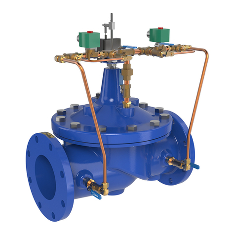
CLA-VAL 58-01 Installation and operating instructions

Combination Back Pressure & Solenoid
Shut-off Valve
INSTALLATION / OPERATION / MAINTENANCE
58-01/658-01
MODEL
INTRODUCTION
The Cla-Val Model 58-01/658-01 valve performs two separate func-
tions. When the solenoid is activated, it maintains a constant back
pressure by discharging excess pressure downstream. When the
solenoid is de-activated, the valve closes drip-tight. When the sole-
noid is activated, the valve is actuated by hydraulic line pressure
through the pilot control system. When inlet pressure is greater than
the control setting, the valve opens. When inlet pressure is equal to
the control setting, the pilot modulates the valve, maintaining the pre-
selected back pressure. When inlet pressure is less than the control
setting, the pilot system closes the valve drip tight. Changing the
pressure setting simply involves turning an adjusting screw on the
pilot control.
INSTALLATION
1. Allow sufficient room around the valve assembly to make adjust-
ments and for servicing.
2. lt is recommended that gate or block valves be installed to facili-
tate isolating valve for preventative maintenance. When used as a
surge control or pressure relief valve where valve outlet discharge
is to atmosphere, then a gate or block valve is needed at valve
inlet. When used as a back pressure sustaining control valve
where valve outlet is connected to pressurized downstream sys-
tem, then gate or block valves are needed at valve inlet and outlet.
NOTE: BEFORE THE VALVE IS INSTALLED, PIPE LINES
SHOULD BE FLUSHED OF ALL FOREIGN MATTER.
3. Place valve in line with flow through valve in direction indicated
on inlet plate or flow arrows. Check all fittings and hardware for
proper makeup and verify that no apparent damage is evident.
4. Cla-Val Valves operate with maximum efficiency when mounted
in horizontal piping with the cover UP; however, other positions are
acceptable. Due to size and weight of cover and internal compo-
nents on six inch and larger valves, installation with the cover up is
advisable. This makes periodic inspection of internal parts readily
accessible.
5. Caution must be taken in the installation of this valve to insure that
galvanic and/or electrolytic action does not take place. The proper
use of dielectric fittings and gaskets are required in all systems using
dissimilar metals.
OPERATION AND START-UP
1. Prior to pressurizing the valve assembly make sure the necessary
gauges to measure pressure in the system, are installed as required
by the system engineer. A Cla-Val X101 Valve Position Indicator may
be installed in the center cover port to provide a visual indication of
the valve stem position during startup adjustment..
CAUTION: During start-up and test a large volume of water may
be discharged downstream. Check that the downstream venting is
adequate to prevent damage to personnel and equipment. All
pilot adjustments should be made slowly in small increments.
If the main valve closes too rapidly it may cause surging in
upstream piping.
2. If isolation valves (B) are installed in pilot system open these
valves (see schematic).
3. The three-way Solenoid Control applies or relieves pressure in
the cover chamber of the Auxiliary Hytrol Valve (5) in the control
piping. The following action takes place:
4. Loosen jam nut on X42N-2 strainer valve assembly and turn
adjusting stem clockwise until it seats. Then turn stem counterclock-
wise 1/4 to 1/2 turn and tighten jam nut for an initial setting.
5. Remove cap on the CRL Pressure Relief Control, loosen jam nut
and turn adjusting screw clockwise until spring is fully compressed.
This puts the control in full closed mode and will cause the main
valve to close when system is pressurized.
6. If a downstream block valve is installed, slowly open this valve.
7. Partially open upstream block valve. The main valve should
close.
8. Carefully loosen the plug at top of indicator assembly. If an indi-
cator (X101) is installed, loosen the bleed valve at top of indicator.
Bleed air from cover and tighten plug or bleed valve.
Carefully loosen tubing fittings at highest points and bleed air from
system. Retighten fittings.
9. Open fully the upstream block valve and turn the CRL adjusting
screw slowly counterclockwise until you begin to hear a flow through
the control. The main valve should start to open. If the pressure is
below the required relief setting, refer to the spring chart and turn the
adjusting screw clockwise the number of turns required for the prop-
er setting. Lock the jam nut and replace cover. An observation of the
pressure relief setting should be made during usage. The controls
can be readjusted as required.
10. To check the operation of the solenoid shutoff feature, alternate-
ly energize and de-energize the solenoid to open and close the main
valve. The main valve should alternately close drip tight and open to
set point of the CRL. The optional manual operator on solenoid over-
rides operation by shifting it to the energized position when small red
knob is fully turned clockwise. By turning small red knob counter-
clockwise fully normal solenoid operation is restored.
MAINTENANCE
1. Cla-Val Valves and Controls require no lubrication or packing and
a minimum of maintenance. However, a periodic inspection sched-
ule should be established to determine how the fluid is affecting the
efficiency of the valve assembly. Minimum of once per year.
2. Repair and maintenance procedures of the Hytrol Main Valve and
control components are included in a more detailed IOM manual. It
can be downloaded from our web site (www.cla-val.com) or obtained
by contacting a Cla-Val Regional Sales Office.
3. When ordering parts always refer to the catalog number and
stock number on the valve nameplate.
Solenoid Control (4)
Energized to Open
Cla-Val 58-01
De-Energized to Open
Cla-Val 58-01
Position Port Flow
Auxiliary (5) and
Main Valve (1)
Auxiliary (5) and
Main Valve (1)
Energized 1 to 2
OPEN RELIEVES
COVER PRESSURE
CLOSED APPLIES
COVER PRESSURE
De-Energized 1 to 3
CLOSED APPLIES
COVER PRESSURE
OPEN RELIEVES
COVER PRESSURE
Distributed By: M&M Control Service, Inc.
www.mmcontrol.com/claval-index.php
800-876-0036 847-356-0566
X42N-3
CS3
CK2
CV
2.
4
B.
S.
H
3
4
F
B1
D1
S
2
B2
B1
1
D2
D3
5
DRAIN TO
ATMOSPHERE
REMOTE
SENSING
CS3
3
1
2
INLET OUTLET
58-01/658-01 SCHEMATIC CRL
Ajusting Screw
(3/8" - 16UNF THREAD)
INLET
1/8 - 27 NPT
SENSING
CONNECTION
OUTLET
Cap
Screw, Adjusting
Nut Hex (Locking)
Cover
Guide, Spring
Spring
Washer, Belleville
Washer, Diaphragm
(Upper)
Screw Fil. Hd.*
Diaphragm*
Washer, Diaphragm
(Lower)
O-Ring, Stem*
Nameplate
Body, Powerunit
O-Ring, Body*
Body
Nut, Hex,Stem, Lower
Seat
O-Ring, Seat
Guide, Spring
Nut, Stem, Upper
*O-Ring, Stem
Stem
*Disc Retainer Assy.
1/2" or 3/4" NPT
(2 places)
3
CRL adjust range (psi) Spring Color psi change per turn*
0 - 75 Red 8.5
20 - 200 Green 28
100 - 300
* approximate. Use gauge at valve inlet to set.
Chrome Vanadium 18
X140-1
Security Cap
Option
BASIC COMPONENTS
1 100-01 Hytrol (Main Valve)
2 X42N-3 Strainer Needle Valve
3 CRL Pressure Relief Control
4 CS3 Solenoid Control
5 100-01 Hytrol (Reverse Flow)
OPTIONAL FEATURES
B CK2 (Isolation Valve)
D Check Valves with (Isolation valve)
F Remote Pilot Sensing
H Drain to Atmosphere
S CV Flow Control (Opening)
100-01 Hytrol (Reverse Flow)
5
CDC-1
D
For a more information go to www.mmcontrol.com or call 1-800-876-0036.
N-58-01/658-01 (R-1/08)
COVER
PIPE PLUG
COVER BEARING
SPRING
STEM NUT
DIAPHRAGM WASHER
DISC RETAINER
BODY
*SPACER WASHERS
DISC GUIDE
SEAT
PIPE PLUG
STEM
SEAT O-RING
STUD
8" and Larger
*DIAPHRAGM
*DISC
*Repair Parts
Seat Screw
8" and Larger
(Globe
or
Angle)
PIPE PLUG
HEX NUT
8" and Larger
Cover Bolt
6" and Smaller
HYTROL MAIN VALVE
1
SYMPTOM PROBABLE CAUSE REMEDY
Main valve
won't open
Inlet pressure below setting of
pilot valve
Reset pilot valve. If change in
setting is from tampering seal
cap with wire and lead seal.
Pilot valve stuck closed. Mineral
deposit or foreign material
between disc retainer and
powerunit body.
Disassemble control and
clean
Pilot valve diaphragm ruptured or
diaphragm nut loose. Water com-
ing out of the vent hole in cover.
Disassemble and replace
diaphragm. Tighten nut.
Main valve stuck closed Disassemble main valve
Mineral buildup on stem.
Stem damaged
Clean parts and/or replace
damaged part. Check down-
stream and cover CK2 isola-
tion valve are open.
Main Valve
won’t close
Inlet pressure above setting of
pilot valve Reset pilot valve
Clogged needle valve or strainer Disassemble and clean
Pilot valve stuck open. Mineral
deposit or foreign material under
disc retainer or under diaphragm
assembly.
Disassemble and clean
Main valve stuck open. Mineral
buildup on stem. Foreign material
between seat and disc assembly.
Disassemble and clean
Main valve diaphragm worn Disassemble and replace
Valve leaks
continuously
Pilot valve disc worn out Disassemble and replace
Main valve disc worn or small pin
hole in main valve diaphragm Disassemble and replace
Set-point too close to inlet pres-
sure Reset CRL Pilot Control
Solenoid
Valve
will not
operate
Solenoid Symptoms
Solenoid voltage
Check voltage across coil
leads must be minimum of
85% of nameplate rating
Burned out solenoid coil Check for open circuit coil
Replace coil
Distributed By: M&M Control Service, Inc.
www.mmcontrol.com/claval-index.php
800-876-0036 847-356-0566

This manual suits for next models

1

Other CLA-VAL Control Unit manuals

CLA-VAL 790-01 Owner's manual

CLA-VAL

CLA-VAL 790-01 Owner's manual

CLA-VAL 750-20 Owner's manual

CLA-VAL

CLA-VAL 750-20 Owner's manual

CLA-VAL 50-20 Instruction manual

CLA-VAL

CLA-VAL 50-20 Instruction manual

CLA-VAL 90-21 UL Instruction manual

CLA-VAL

CLA-VAL 90-21 UL Instruction manual

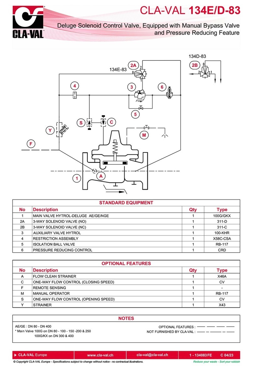
CLA-VAL 134E-83 User manual

CLA-VAL

CLA-VAL 134E-83 User manual

CLA-VAL 92-01 Owner's manual

CLA-VAL

CLA-VAL 92-01 Owner's manual

CLA-VAL 50B-4KG1 General instructions

CLA-VAL

CLA-VAL 50B-4KG1 General instructions

CLA-VAL 40-01/640-01 Owner's manual

CLA-VAL

CLA-VAL 40-01/640-01 Owner's manual

CLA-VAL 39A User manual

CLA-VAL

CLA-VAL 39A User manual

CLA-VAL 136-AU User manual

CLA-VAL

CLA-VAL 136-AU User manual

CLA-VAL 750B-4KG1 Owner's manual

CLA-VAL

CLA-VAL 750B-4KG1 Owner's manual

CLA-VAL 50B-4KG1 Owner's manual

CLA-VAL

CLA-VAL 50B-4KG1 Owner's manual

CLA-VAL 90-21 Owner's manual

CLA-VAL

CLA-VAL 90-21 Owner's manual

CLA-VAL 50B-4KG1 Installation and operating instructions

CLA-VAL

CLA-VAL 50B-4KG1 Installation and operating instructions

CLA-VAL RP-2 User manual

CLA-VAL

CLA-VAL RP-2 User manual

CLA-VAL 340-07 General instructions

CLA-VAL

CLA-VAL 340-07 General instructions

CLA-VAL 131-01 General instructions

CLA-VAL

CLA-VAL 131-01 General instructions

CLA-VAL 50B-5KG Owner's manual

CLA-VAL

CLA-VAL 50B-5KG Owner's manual

CLA-VAL 90-01 Owner's manual

CLA-VAL

CLA-VAL 90-01 Owner's manual

CLA-VAL 60-31 General instructions

CLA-VAL

CLA-VAL 60-31 General instructions

CLA-VAL 81-02/681-02 Owner's manual

CLA-VAL

CLA-VAL 81-02/681-02 Owner's manual

CLA-VAL 92-07 Owner's manual

CLA-VAL

CLA-VAL 92-07 Owner's manual

CLA-VAL 43-01/643-01 User manual

CLA-VAL

CLA-VAL 43-01/643-01 User manual

CLA-VAL 90G-21 UL Instruction manual

CLA-VAL

CLA-VAL 90G-21 UL Instruction manual

Popular Control Unit manuals by other brands

Festo CPX-FVDA-P2 manual

Festo

Festo CPX-FVDA-P2 manual

Siemens 7KT1 908 operating instructions

Siemens

Siemens 7KT1 908 operating instructions

Praher Plastics Aquastar Easy Replacement manual

Praher Plastics

Praher Plastics Aquastar Easy Replacement manual

Ingersoll-Rand VHP600CM Operation & maintenance manual

Ingersoll-Rand

Ingersoll-Rand VHP600CM Operation & maintenance manual

Eaton Powerware 9125 user guide

Eaton

Eaton Powerware 9125 user guide

axing premium-line ONX 1550-01 Operation instructions

axing

axing premium-line ONX 1550-01 Operation instructions

Rtelligent T60-IO user manual

Rtelligent

Rtelligent T60-IO user manual

Dinstar DXP60 quick start guide

Dinstar

Dinstar DXP60 quick start guide

GE IC3645SR4T405E1 Installation and operation manual

GE

GE IC3645SR4T405E1 Installation and operation manual

Synergy SYPM S5BC installation instructions

Synergy

Synergy SYPM S5BC installation instructions

Toro E101B Programming Instruction

Toro

Toro E101B Programming Instruction

MFB KRAFTZWERG owner's manual

MFB

MFB KRAFTZWERG owner's manual

Wiznet W5500S2E-S1 user manual

Wiznet

Wiznet W5500S2E-S1 user manual

Vindum CV Series manual

Vindum

Vindum CV Series manual

SinoCon KonNad C2000-A2-SDD4040-BB3 user manual

SinoCon

SinoCon KonNad C2000-A2-SDD4040-BB3 user manual

Bailey Infi 90 NTAI02 Instruction

Bailey

Bailey Infi 90 NTAI02 Instruction

Sanipex AQUAECO AQP-ECO-U750P-CP installation guide

Sanipex

Sanipex AQUAECO AQP-ECO-U750P-CP installation guide

Interpump Group Pratissoli S723 operating instructions

Interpump Group

Interpump Group Pratissoli S723 operating instructions

manuals.online logo
manuals.online logoBrands
  • About & Mission
  • Contact us
  • Privacy Policy
  • Terms and Conditions

Copyright 2025 Manuals.Online. All Rights Reserved.