manuals.online logo
Brands
  1. Home
  2. •
  3. Brands
  4. •
  5. CLA-VAL
  6. •
  7. Control Unit
  8. •
  9. CLA-VAL 60-73 User manual

CLA-VAL 60-73 User manual

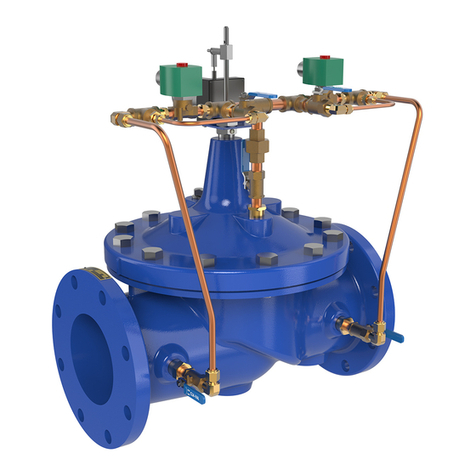
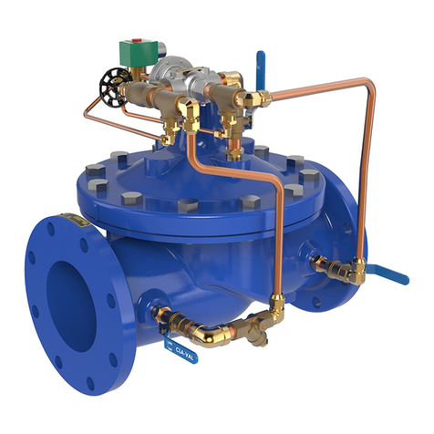
Booster Pump Control Valve
60-73
MODEL
• Simple Hydrauli Operation
• Low Head Loss
• Horizontal or Verti al Mounting
• Built-in Che k Valve
• Proven Reliable Design
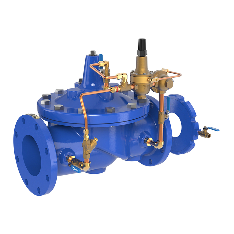
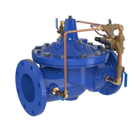
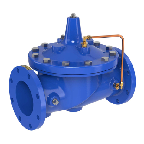
The Cla-Val Model 60-73 Booster Pump Control Valve is a pilot-
operated valve designed for installation on the discharge of booster
pumps to eliminate pipeline surges caused by the starting and
stopping of the pump.
The pump starts against a closed valve. When the pump is started,
the solenoid control is energized and the valve begins to open slowly,
gradually increasing line pressure to full pumping head. When the
pump is signaled to shut-off, the solenoid control is de-energized and
the valve begins to close slowly, gradually reducing flow while the
pump continues to run. When the valve is closed, a limit switch
assembly, which serves as an electrical interlock between the valve
and the pump, releases the pump starter and the pump stops.
Should a power failure occur, a built-in lift-type check valve closes
the moment flow stops, preventing reverse flow regardless of
solenoid or diaphragm assembly position.
S hemati Diagram
Item Des ription
1 Powercheck Main Valve 100-30
2 CV Flow Control
3 CSM11-A2-2 Solenoid Control
4 X10⁵LCW Switch Assembly
5 CVS-1 Shuttle Valve
Optional Features
Item Des ription
A X46A Flow Clean Strainer
B CK2 Isolation Valve
Y X43 "Y" Strainer
Discharge to
Atmosphere Discharge to
System
Isolation Valve
Pump
CLA-VAL
52-03/652-03
Surge Anticipator
Valve CLA-VAL
60-73 Booster
Pump Control
Valve
Typi al Installation
Install Model 60-73 valve as shown. Flexible conduit should be used for
electrical connections to the solenoid control and the limit switch. The
Model 52-02 or 652-03 Surge Anticipator Valve is recommended for
power failure protection.
Note:
Valve stem can be located in either vertical up or horizontal position.
Materials
Pressure Ratings (Recommended Maximum Pressure - psi)
Valve Body & Cover Pressure Class
Flanged Threaded
Grade Material ANSI
Standards*
150
Class
300
Class
End‡
Details
ASTM A536 Ductile Iron B16.42 250 640 400
ASTM A216-WCB Cast Steel B16.5 285 720 400
UNS 87850 Bronze B16.24 225 500 400
Note: * ANSI standards are for flange dimensions only.
Flanged valves are available faced but not drilled.
‡ End Details machined to ANSI B2.1 specifications.
Valves for higher pressure are available; consult factory for details
Component Standard Material Combinations
Body & Cover Ductile Iron Cast Steel Bronze
100-30 Sizes (mm) 65 - 200 mm 65 - 200 mm 65 - 200 mm
Disc Retainer &
Diaphragm Washer Cast Iron Cast Steel Bronze
Trim: Disc Guide,
Seat & Cover Bearing
Bronze is Standard
Stainless Steel is Optional
Disc Buna-N®Rubber
Diaphragm Nylon Reinforced Buna-N®Rubber
Stem, Nut & Spring Stainless Steel
For material options not listed, consult factory.
Cla-Val manufactures valves in more than 50 different alloys.
Y
Z
Dimensional Data
G
GG
GGG
D
Inlet DD
DDD
F
FF
X
100-30
Threaded &
Flanged
A
E
C
(MAX)
K
J
H
Inlet Outlet
AA
AAA
B(Diameter)
60-73 Series Dimensions (Full Internal Port 100-30) (mm)
65
279
279
295
203
262
140
140
148
43
89
95
102
102
110
0.50
0.50
0.50
18
30
432
254
254
80
318
305
337
232
284
159
152
168
52
95
105
114
102
111
0.50
0.50
0.50
20
43
457
279
279
100
381
397
292
362
191
198
—
—
—
81
114
127
127
135
0.75
0.75
0.75
28
86
533
305
305
150
508
533
400
468
254
267
—
—
109
140
159
—
152
165
0.75
0.75
0.75
43
145
864
508
508
200
645
670
508
554
322
335
—
—
—
135
171
191
203
216
1.00
1.00
1.00
58
295
940
1067
1067
Valve Size (mm)
AThreaded
AA 150 ANSI
AAA 300 ANSI
BDiameter
CMaximum
DThreaded
DD 150 ANSI
DDD 300 ANSI
E
F150 ANSI
FF 300 ANSI
GThreaded
GG 150 ANSI
GGG 300 ANSI
HNPT Body Tapping
JNPT Cover Center Plug
KNPT Cover Tapping
Stem Travel
Approx. Ship Weight (kgs)
Approx. XPilot System
Approx. YPilot System
Approx. ZPilot System
Temperature Range
Water to 82°C Max
Materials
Standard Pilot System Materials
Pilot Control: Low Lead Bronze
Trim: Stainless Steel Type 303
Rubber: Buna-N®Synthetic Rubber
Optional Pilot System Materials
Pilot Systems are available with
optional Aluminum, Stainless Steel
or Monel materials.
Pilot System Spe ifi ations
CSM11 Solenoid Control Power
Consumption
Enclosure General purpose NEMA Type 3; Aluminum
Note: For other enclosures and
NEMA Types, consult factory
ousing Body — Aluminum
Trim — Stainless Steel
Operating Pressure: Maximum pressure 300 psi,
for higher pressure consult factory. AC or DC
Coil Insulation Class A (molded)
AC voltage 15.4 watts
DC voltage 16.8 watts
Auto Off Hand
L1 SW
1
A3CR3
L2
1CR
H
1CR
1CR
3CR1
N.C. 2CR
PVS
2CR
3CR
M
COM.
SW2N.O.
3CR22CR
Wiring Diagram
Auto-Off- and = Selector Switch
1CR = Relay, DPST Normally Open
2CR = Relay, DPST Normally Open
3CR = Relay, TPST Normally Open
SW1 = Switch, Remote Start, Automatic
SW2
= Switch, SPDT, Valve Limit Switch
Connect to N.C. Terminal
PVS = Pilot Valve Solenoid
M = Pump Motor Starter
Note: SW2and PVS supplied by Cla-Val. All other electrical items
supplied by customer. SW2is included in the X105L switch as-
sembly which is mounted on the pump control valve cover.
Shown In Pump Off Position
Volts Amperes Volts Amperes Coil
Resistance
DC olding Pull In AC 60 z olding Inrush Ohms
24 .603 24 24 2.88 25.4 0.5
28.629 120 120 .575 5.1 14.1
32 .500 208 208 .330 2.93 40
48 .293 240 240 .288 2.54 58
115 .122 440 440 .156 1.38 174
125 .119 480 440 .143 1.27 233
252 .072 2.45
Volts Amperes Coil
Resistance
(AC 50 z) olding Inrush Ohms
110 .48 4.6 15.7
220 .24 2.3 66
240 .22 2.1 88
When Ordering, Please
Spe ify:
1. Catalog No. 60-73
2. Valve Size
3. Pattern - Globe or Angle
4. Pressure Class
5. Trim Material
6. Electrical Selection
7. Desired Options
8. When Vertically Installed
9. Epoxy Coating
CSM11 Spe ifi ations
CSM11 Solenoid Control How to Order
60-73
Valve
Sele tion
100-30 Pattern: Globe (G), Angle (A), End Conne tions: Threaded (T), Grooved (GR), Flanged (F) Indicate Available Sizes
millimeters
(mm) 65 80 100 150 200
Main Valve
100-30
Pattern G, A G, A G, A G, A G, A
End Detail T, F T, F FFF
Suggested
Flow
(gpm)
Maximum 300 460 800 1800 3100
Maximum
Intermittent 370 580 990 2250 3900
Suggested
Flow
(Liters/Sec)
Maximum 19 29 50 113 195
Maximum
Intermittent 23 37 62 142 246
100-30 Series is the full internal port Power he k.
Stopping Cy le...
Starting switch opens, solenoid control "A" de-
energizes and shifts, pump continues to run.
igh Pressure fluid from the pump is directed
above the diaphragm, applying force to close the
valve.
The valve closes slowly as fluid from the lower
diaphragm chamber is gradually released to
atmosphere through speed control "D" and
solenoid "A". When the valve closes fully, the
limit switch " " shuts off the pump.
Pump Off...
With pump off, static line pressure is
transmitted through strainer "F", shuttle
valve "C", solenoid control "A", and speed
control "E" to the chamber above the
diaphragm, thus holding the valve closed.
If power failure occurs when valve is open,
the built-in check valve "J" closes
immediately to prevent reverse flow.
Starting Cy le...
Starting switch closes, pump starts, solenoid control
"A" energizes and shifts allowing fluid from upper
diaphragm chamber to drain to atmosphere. igh
pressure fluid from pump enters strainer "B" and shifts
shuttle valve "C", which always supplies the highest
pressure from either strainer "B" or "F". igh pressure
fluid is transmitted to the lower diaphragm chamber
and opens the valve.The opening speed of the valve is
controlled by speed control "E", which limits the rate
fluid is relieved from above the diaphragm.
Sequen e Of Operation
Drain PT. 1
A
D
EH
Enter PT.2
C
B
J
F
Drain
A
EHD
Enter PT.2
PT.1
F
B
C
A
Drain
Enter
C
PT.1
PT.2
EH
D
F
B
CLA-VAL
1701 Placentia Ave •Costa Mesa CA 92627 •Phone: 949-722-4800 •Fax: 949-548-5441 •E-mail: [email protected] •www.cla-val.com
Copyright Cla-Val 2019
•
Printed in USA
•
Specifications subject to change without notice.
©
E-60-73 Metric (R-02/2019)
Optional Ele troni Control
The Cla-Val PC-22D provides control of the pump and
pump control valve, preventing surges in the system
when the pump starts or stops. It consists of a pre-wired
electrical control panel employing a programmable
valve controller to sequence the pump and pump
control valve during all modes of operation. Provides
added protection to the pumping system from damage
caused by mechanical, hydraulic or power failure.
The PC-22D offers all the control features found in the
recommended wiring diagrams for Cla-Val pump control
valves, plus alarms, automatic shutdown and adjustable
timers.
Valve Sizing
Sizing Model 60-73 Booster Pump Control
Valves is similar to sizing non-modulating type
valves. Simply select the smallest size valve that
will handle the pump output at an acceptable
head loss for the application.
Do not oversize. Oversizing a Booster Pump
Control Valve will nullify its ability to prevent
surges caused by the starting and/or stopping
of the pump. Maximum flow values are given in
the selection table above. For further
information on flow characteristics for this valve,
reference the 100-30 (60-73) technical data
sheet.
Example:
A booster pump station with a rated output of
1000 GPM and 4 psi is an acceptable head loss
for the application.
Drain Provisions
Each time the valve opens or closes, water is
discharged from the solenoid exhaust port, the
amount varying with the valve size. Provisions
should be made for the disposal of this water.
Exhaust tube must be free of any back pressure.
Provide an air gap between the solenoid
exhaust tube and drain facility.
Model 60-73 Flow Chart Uses Basic Valve Model 100-30
10 203040 6080100 200 500 1000 2000 5000 10,000 20,000 50,000
1
2
3
4
6
8
10
20
30
40
60
80
100
53
Angle Valve Sizes (Inches)
Globe Valve Sizes (Inches)
80100 150 200
65
Pressure Drop  psi
Flow Rate gpm (water)
100 150 200
65 80
Liquid Volume Displaced from Diaphragm Chamber When Valve Opens or Closes
Sizes (mm) 65 80 100 150 200
60-73 .163 liters .303 liters .640 liters 2.01 liters 4.77 liters
This manual suits for next models
1

Other CLA-VAL Control Unit manuals

CLA-VAL 50-20 Instruction manual

CLA-VAL

CLA-VAL 50-20 Instruction manual

CLA-VAL 81-01 Owner's manual

CLA-VAL

CLA-VAL 81-01 Owner's manual

CLA-VAL 131-01 General instructions

CLA-VAL

CLA-VAL 131-01 General instructions

CLA-VAL 750B-4KG1 Owner's manual

CLA-VAL

CLA-VAL 750B-4KG1 Owner's manual

CLA-VAL 50B-4KG1 Installation and operating instructions

CLA-VAL

CLA-VAL 50B-4KG1 Installation and operating instructions

CLA-VAL 600 Series Owner's manual

CLA-VAL

CLA-VAL 600 Series Owner's manual

CLA-VAL 81-02 User manual

CLA-VAL

CLA-VAL 81-02 User manual

CLA-VAL 340-07 General instructions

CLA-VAL

CLA-VAL 340-07 General instructions

CLA-VAL 750-20 Owner's manual

CLA-VAL

CLA-VAL 750-20 Owner's manual

CLA-VAL 49-01 Installation and operating instructions

CLA-VAL

CLA-VAL 49-01 Installation and operating instructions

CLA-VAL 50-01 Installation and operating instructions

CLA-VAL

CLA-VAL 50-01 Installation and operating instructions

CLA-VAL 39A User manual

CLA-VAL

CLA-VAL 39A User manual

CLA-VAL 98-06 Instruction manual

CLA-VAL

CLA-VAL 98-06 Instruction manual

CLA-VAL CRL-60 Owner's manual

CLA-VAL

CLA-VAL CRL-60 Owner's manual

CLA-VAL CRL Installation and operating instructions

CLA-VAL

CLA-VAL CRL Installation and operating instructions

CLA-VAL 60-73 User manual

CLA-VAL

CLA-VAL 60-73 User manual

CLA-VAL 581 Owner's manual

CLA-VAL

CLA-VAL 581 Owner's manual

CLA-VAL RF-DBF Instruction manual

CLA-VAL

CLA-VAL RF-DBF Instruction manual

CLA-VAL 50B-5KG Installation and operating instructions

CLA-VAL

CLA-VAL 50B-5KG Installation and operating instructions

CLA-VAL 50B-4KG1 Installation and operating instructions

CLA-VAL

CLA-VAL 50B-4KG1 Installation and operating instructions

CLA-VAL 60-31 General instructions

CLA-VAL

CLA-VAL 60-31 General instructions

CLA-VAL 81-02/681-02 Owner's manual

CLA-VAL

CLA-VAL 81-02/681-02 Owner's manual

CLA-VAL 40-01/640-01 Owner's manual

CLA-VAL

CLA-VAL 40-01/640-01 Owner's manual

CLA-VAL 90-21 Owner's manual

CLA-VAL

CLA-VAL 90-21 Owner's manual

Popular Control Unit manuals by other brands

SSS Siedle BMM 611-0 Product information

SSS Siedle

SSS Siedle BMM 611-0 Product information

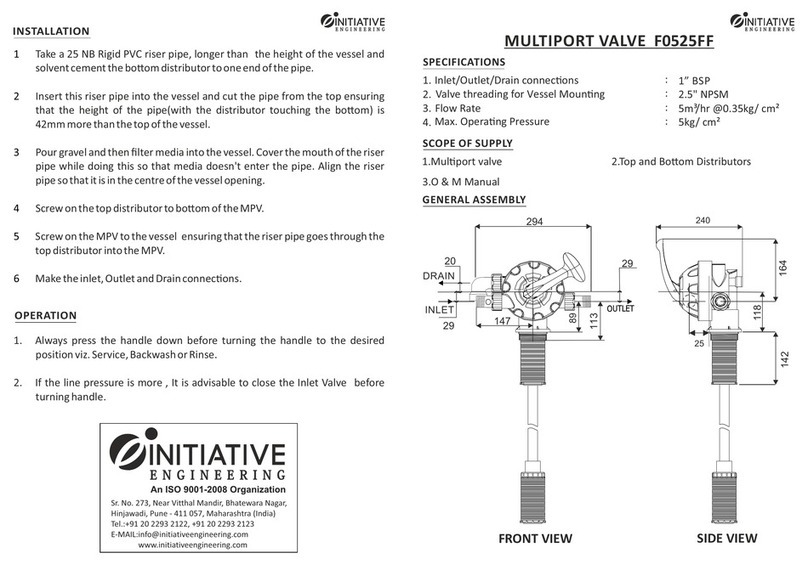
Initiative Engineering F0525FF quick start guide

Initiative Engineering

Initiative Engineering F0525FF quick start guide

SI JANUS installation instructions

SI

SI JANUS installation instructions

Alinx AC7010BB user manual

Alinx

Alinx AC7010BB user manual

Portwell PQ7-M102XL Series user manual

Portwell

Portwell PQ7-M102XL Series user manual

Parker SS1500 Series Installation & service instructions

Parker

Parker SS1500 Series Installation & service instructions

Huawei ME909u-523 Application guide

Huawei

Huawei ME909u-523 Application guide

Sendum PT300D operating manual

Sendum

Sendum PT300D operating manual

ABB Relion REM615 manual

ABB

ABB Relion REM615 manual

Pickering 40-561A user manual

Pickering

Pickering 40-561A user manual

vistaCNC iMachIII P1B manual

vistaCNC

vistaCNC iMachIII P1B manual

mikroElektronika FM Click quick guide

mikroElektronika

mikroElektronika FM Click quick guide

VeeaR EasyVR 3 user manual

VeeaR

VeeaR EasyVR 3 user manual

Eaton Crouse-hinds series operating instructions

Eaton

Eaton Crouse-hinds series operating instructions

Hitachi PSC-5S Installation and operation manual

Hitachi

Hitachi PSC-5S Installation and operation manual

VRG Controls VMO-150 instruction manual

VRG Controls

VRG Controls VMO-150 instruction manual

Alcatel-Lucent 5620 troubleshooting guide

Alcatel-Lucent

Alcatel-Lucent 5620 troubleshooting guide

Hiltron PCM2 quick start guide

Hiltron

Hiltron PCM2 quick start guide

manuals.online logo
manuals.online logoBrands
  • About & Mission
  • Contact us
  • Privacy Policy
  • Terms and Conditions

Copyright 2025 Manuals.Online. All Rights Reserved.