manuals.online logo
Brands
  1. Home
  2. •
  3. Brands
  4. •
  5. Clarion
  6. •
  7. Car Alarm
  8. •
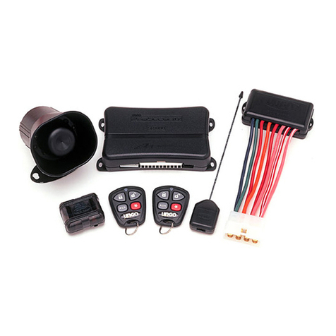
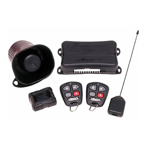
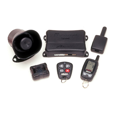
  9. Clarion UNGO ProSecurity S660 User manual

Clarion UNGO ProSecurity S660 User manual

Other manuals for UNGO ProSecurity S660

1

Other Clarion Car Alarm manuals

Clarion UNGO ProSecurity SR6000 User manual

Clarion

Clarion UNGO ProSecurity SR6000 User manual

Clarion UNGO CS105 User manual

Clarion

Clarion UNGO CS105 User manual

Clarion S400 User manual

Clarion

Clarion S400 User manual

Clarion Ungo MS850 User manual

Clarion

Clarion Ungo MS850 User manual

Clarion UNGO MS3001 User manual

Clarion

Clarion UNGO MS3001 User manual

Clarion UNGO MS3200 User manual

Clarion

Clarion UNGO MS3200 User manual

Clarion Ungo MS2000 User manual

Clarion

Clarion Ungo MS2000 User manual

Clarion UNGO MS2005 User manual

Clarion

Clarion UNGO MS2005 User manual

Clarion UNGO MS5500 User manual

Clarion

Clarion UNGO MS5500 User manual

Clarion UNGO PRO SECURITY K20 User manual

Clarion

Clarion UNGO PRO SECURITY K20 User manual

Clarion G1100 User manual

Clarion

Clarion G1100 User manual

Clarion Ungo Pro Security SR9000 User manual

Clarion

Clarion Ungo Pro Security SR9000 User manual

Clarion Ungo Pro Security SR1000 User manual

Clarion

Clarion Ungo Pro Security SR1000 User manual

Clarion Ungo MS2004 User manual

Clarion

Clarion Ungo MS2004 User manual

Clarion UNGO MS5500 Manual

Clarion

Clarion UNGO MS5500 Manual

Clarion UNGO MS8200 User manual

Clarion

Clarion UNGO MS8200 User manual

Clarion UNGO Pro Security S670 User manual

Clarion

Clarion UNGO Pro Security S670 User manual

Clarion UNGO MS2105 User manual

Clarion

Clarion UNGO MS2105 User manual

Clarion UNGO ProSecurity S100 User manual

Clarion

Clarion UNGO ProSecurity S100 User manual

Clarion Ungo Pro Security RK1 User manual

Clarion

Clarion Ungo Pro Security RK1 User manual

Clarion UNGO MS2007 User manual

Clarion

Clarion UNGO MS2007 User manual

Clarion UNGO ProSecurity S660 User manual

Clarion

Clarion UNGO ProSecurity S660 User manual

Clarion UNGO ProSecurity SR5000 User manual

Clarion

Clarion UNGO ProSecurity SR5000 User manual

Clarion UNGO MS2105 User manual

Clarion

Clarion UNGO MS2105 User manual

Popular Car Alarm manuals by other brands

jablotron Athos CA-1202 user manual

jablotron

jablotron Athos CA-1202 user manual

Audiovox AVX1B4S Programming guide

Audiovox

Audiovox AVX1B4S Programming guide

Clifford 3606X owner's guide

Clifford

Clifford 3606X owner's guide

Clifford Nova 3 owner's manual

Clifford

Clifford Nova 3 owner's manual

Ultra Start 2500M SERIES install guide

Ultra Start

Ultra Start 2500M SERIES install guide

Viper 560XV owner's guide

Viper

Viper 560XV owner's guide

Ultra Start 650 Series owner's manual

Ultra Start

Ultra Start 650 Series owner's manual

Audiovox Prestige Platinum+ APS-511C owner's manual

Audiovox

Audiovox Prestige Platinum+ APS-511C owner's manual

Sparkrite SRA8 Guide

Sparkrite

Sparkrite SRA8 Guide

Federal Signal Corporation Pathfinder Siren Series Installation and maintenance manual

Federal Signal Corporation

Federal Signal Corporation Pathfinder Siren Series Installation and maintenance manual

Falcon Predator XL3 Installer manual

Falcon

Falcon Predator XL3 Installer manual

Audiovox Auto Security XR91 Programming guide

Audiovox

Audiovox Auto Security XR91 Programming guide

Clifford Sabre II owner's manual

Clifford

Clifford Sabre II owner's manual

SECO-LARM 300C owner's manual

SECO-LARM

SECO-LARM 300C owner's manual

CrimeStopper CS-8717 Wiring diagram

CrimeStopper

CrimeStopper CS-8717 Wiring diagram

Python 660XP owner's guide

Python

Python 660XP owner's guide

Scytek electronic Vectra X3 product manual

Scytek electronic

Scytek electronic Vectra X3 product manual

Clifford CYBER 2 owner's manual

Clifford

Clifford CYBER 2 owner's manual

manuals.online logo
manuals.online logoBrands
  • About & Mission
  • Contact us
  • Privacy Policy
  • Terms and Conditions

Copyright 2025 Manuals.Online. All Rights Reserved.

NOTE: This product is intended for installation by a professional installer only!
Any attempt to install this product by any person other than a trained professional
may result in severe damage to a vehicle’s electrical system and components.
PPrrooSSeeccuurriittyy
Model S660
installation guide
22
33
ttaabblleeooffccoonntteennttss
wwaarrnniinngg!!ssaaffeettyyffiirrsstt................................................44
iinnssttaallllaattiioonnppooiinnttssttoorreemmeemmbbeerr................................44
before beginning the installation . . . . . . . . . . . . 4
after the installation . . . . . . . . . . . . . . . . . . . . . 4
ddeecciiddiinnggoonnccoommppoonneennttllooccaattiioonnss..............................55
locations for the siren . . . . . . . . . . . . . . . . . . . . 5
locations for the control module . . . . . . . . . . . . . 5
locations for stinger doubleguard shock sensor . . . 6
locations for valet/program switch . . . . . . . . . . . 7
locations for the status LED . . . . . . . . . . . . . . . . 7
locations for the optional starter kill relay . . . . . . 8
ffiinnddiinnggtthheewwiirreessyyoouunneeeedd........................................88
obtaining constant 12V . . . . . . . . . . . . . . . . . . . 8
finding the 12V switched ignition wire. . . . . . . . . 9
finding the starter wire . . . . . . . . . . . . . . . . . . . 9
finding a (+) parking light wire . . . . . . . . . . . . . 10
finding the door pin switch circuit. . . . . . . . . . . 11
mmaakkiinnggyyoouurrwwiirriinnggccoonnnneeccttiioonnss..............................1122
pprriimmaarryyhhaarrnneessss((HH11)),,1122--ppiinnccoonnnneeccttoorr....................1133
aauuxxiilliiaarryyhhaarrnneessss((HH22)),,66--ppiinnccoonnnneeccttoorr....................1133
ddoooorrlloocckkhhaarrnneessss,,33--ppiinnccoonnnneeccttoorr..........................1144
rriibbbboonnhhaarrnneessss,,wwiirriinnggddiiaaggrraamm................................1144
pprriimmaarryyhhaarrnneessss((HH11))wwiirreeccoonnnneeccttiioonngguuiiddee..............1155
sseeccoonnddaarryyhhaarrnneessss((HH22))wwiirreeccoonnnneeccttiioonngguuiiddee..........2200
pplluugg--iinnLLEEDDaannddvvaalleett//pprrooggrraammsswwiittcchh......................2222
pprrooggrraammmmeerriinntteerrffaaccee,,33--ppiinnbbllaacckkpplluugg....................2222
sshhoocckksseennssoorrhhaarrnneessss,,44--ppiinnccoonnnneeccttoorr......................2233
pprrooggrraammmmiinnggjjuummppeerrss............................................2244
light flash (+)/(-) . . . . . . . . . . . . . . . . . . . . . . 24
ttrraannssmmiitttteerr//rreecceeiivveerrlleeaarrnnrroouuttiinnee™™..........................2244
ttrraannssmmiitttteerrccoonnffiigguurraattiioonnss......................................2266
standard configuration . . . . . . . . . . . . . . . . . . . 26
mmuullttii--lleevveellsseeccuurriittyyaarrmmiinngg......................................2288
ssyysstteemmffeeaattuurreesslleeaarrnnrroouuttiinnee..................................2288
ffeeaattuurreemmeennuuss........................................................3300
menu #1 - basic features . . . . . . . . . . . . . . . . . 30
menu #2 - advanced features . . . . . . . . . . . . . . 31
ffeeaattuurreeddeessccrriippttiioonnss................................................3311
menu #1 - basic features . . . . . . . . . . . . . . . . . 31
menu #2 - advanced features . . . . . . . . . . . . . . 33
nnuuiissaanncceepprreevveennttiioonncciirrccuuiittrryy™™....
............................3355
vvaalleettmmooddee...........................................................
.3355
ttaabblleeooffzzoonneess........................................................3366
lloonnggtteerrmmeevveenntthhiissttoorryy..........................................3366
ttrroouubblleesshhoooottiinngg....................................................3377
alarm troubleshooting . . . . . . . . . . . . . . . . . . . 37
wwiirriinnggqquuiicckkrreeffeerreenncceegguuiiddee....................................3388
44
wwaarrnniinngg!!ssaaffeettyyffiirrsstt
The following safety warnings must be observed at all times:
■Due to the complexity of this system, installation of this product must only be performed by an authorized
Ungo dealer.
iinnssttaallllaattiioonnppooiinnttssttoorreemmeemmbbeerr
■Please read this entire installation guide before beginning the installation. The installation of this remote
start system requires interfacing with many of the vehicle’s systems. Many new vehicles use low-voltage or
multiplexed systems that can be damaged by low resistance testing devices, such as test lights and logic
probes (computer safe test lights). Test all circuits with a high quality digital multi-meter before making con-
nections.
■Do not disconnect the battery if the vehicle has an anti-theft-coded radio. If equipped with an air bag, avoid
disconnecting the battery if possible. Many airbag systems will display a diagnostic code through their
warning lights after they lose power. Disconnecting the battery requires this code to be erased, which can
require a trip to the dealer.
■Check with the customer on status LED location.
■Remove the domelight fuse. This prevents accidentally draining the battery.
■Roll down a window to avoid being locked out of the car.
■Test all functions. The “Using Your System” section of the Owner's Guide is very helpful when testing.
■When testing, don’t forget that this system is equipped with Nuisance Prevention Circuitry™(NPC™). NPC can
bypass trigger zones, making them appear to stop working. See the
Nuisance Prevention Circuitry
section.
■Review and complete the
Safety Check
section of this guide prior to the vehicle reassembly.
aafftteerrtthheeiinnssttaallllaattiioonn
bbeeffoorreebbeeggiinnnniinnggtthheeiinnssttaallllaattiioonn
55
ddeecciiddiinnggoonnccoommppoonneennttllooccaattiioonnss
SSoommeetthhiinnggssttoorreemmeemmbbeerraabboouuttmmoouunnttiinnggtthheessiirreenn::
■Keep it away from heat sources, such as radiators, exhaust manifolds, turbochargers, and heat shields.
■Mount it where a thief cannot easily disconnect it, whether the hood is open or shut. Both the siren and its
wires should be difficult to find. This usually involves disguising the wire to look like a factory harness.
■We recommend against grounding the siren to its mounting screws. Instead, we recommend running both the
red and black wires into the passenger compartment and grounding to one common point for all devices.
After all, both wires are the same length and come already bonded together. Whenever possible, conceal your
wires in the factory harnesses or in the same style loom as the factory.
■When possible, place the siren on the same side of the vehicle as the control module, where its wires will
reach the control module’s wires without extending them. Always run the wires through the center of a
grommet, never through bare metal!
■Point the siren down so water does not collect in it.
SSoommeetthhiinnggssttoorreemmeemmbbeerraabboouuttwwhheerreetto
ommoouunntttthheeccoonnttrroollmmoodduullee::
■Never put the control module in the engine compartment!
■The first step in hot-wiring a vehicle is removing the driver's side under-dash panel to access the starter and
ignition wires. If the control module is placed just behind the driver's side dash it can easily be disconnected.
■When mounting the control module, try to find a secure location that will not require you to extend the harnesses’
wires (they are 1.5 meters long). Keep it away from the heater core (or any other heat sources) and any obvious leaks.
llooccaattiioonnssffoorrtthheeccoonnttrroollmmoodduullee
llooccaattiioonnssffoorrtthheessiirreenn
66
■The higher the control module is in the vehicle, the better the transmitter range will be. If you put the
control module under a seat or inside a metal dashboard, range will diminish.
Some good control module locations: above the glove box, inside the center console, above the under-dash fuse
box, above the radio, etc.
SSoommeetthhiinnggssttoorreemmeemmbbeerraabboouuttwwhheerreettoommoouunntttthheesshhoocckksseennssoorr::
■Never put the Stinger®in the engine compartment!
■Find a spot close to the control module so that the wires do not need to be extended. Keep it away from the
heater core (or any other heat sources) and any obvious leaks.
HHoowwtthheeSSttiinnggeerr®®iissmmoouunntteeddiisstthheemmoossttiimmppoorrttaannttffaaccttoorriinniittssppeerrffoorrmmaannccee..WWeerreeccoommmmeennddttwwoommeetthhooddss::
■Using double-sided tape or hook-and-loop fastener to mount to a trim panel or an air duct, or
■Wire-tying to a wire harness.
If mounting the sensor where it cannot be easily reached for adjustment, hook-and-loop fastening tape (such as
Velcro) is recommended for ease of removal for future adjustments.
NNOOTTEE::In many vehicles, tying the sensor to a steering column or screwing it to metal will result
in poor sensitivity, especially at the rear of the vehicle.
llooccaattiioonnssffoorrssttiinnggeerrddoouubblleegguuaarrddsshhoocckksseennssoorr
77
IIMMPPOORRTTAANNTT!!When the vehicle is delivered, please show the user where this switch is located
and how to disarm the system with it.
Ensure that the location you pick for the switch has sufficient clearance to the rear. The switch should be well
hidden. It should be placed so passengers or stored items (such as in a glove box or center console) cannot acci-
dentally hit it. The switch fits into a 9/32-inch hole.
This system has Remote Valet. The user can enter and exit Valet® Mode without having to reach the
Valet®/Program switch. This feature was introduced so that switch location was less critical in day-to-day use.
As long as the Valet®/Program switch can be reached to disarm without a transmitter, easy access is not important.
TThhiinnggssttoorreemmeemmbbeerrwwhheennppoossiittiioonniinnggtthheeSSttaattuussLLEEDD::
■It should be visible from both sides and the rear of the vehicle, if possible.
■It needs at least 1/2-inch clearance to the rear.
■It is easiest to remove a small panel, such as a switch blank or a dash bezel, before drilling a 9/32-inch hole.
■Use quick-disconnects near the LED wires if the panel is removable. This lets mechanics or other installers
remove the panel without cutting the wires.
llooccaattiioonnssffoorrtthheessttaattuussLLEEDD
llooccaattiioonnssffoorrvvaalleett//pprrooggrraammsswwiittcchh
88
If optional starter kill relay or its connections are immediately visible upon removal of the under-dash panel,
they can easily be bypassed. Always make the relay and its connections difficult to discern from the factory
wiring! Exposed yellow butt connectors do not look like factory parts, and will not fool anyone! For this reason,
routing the optional starter kill wires away from the steering column is recommended.
ffiinnddiinnggtthheewwiirreessyyoouunneeeedd
Now that you have decided where each component will be located, you’re going to find the wires in the car that
the security system will be connected to.
IIMMPPOORRTTAANNTT!!Do not use a 12V test light or logic probe (computer safe test light) to find these
wires! Use a digital multimeter for all testing.
We recommend two possible sources for 12V constant: the (+) terminal of the battery, or the constant supply to
the ignition switch. Always install a fuse within 12 inches of this connection. If the fuse also will be powering
other circuits, such as door locks, a power window module, a Nite-Lite® headlight control system, etc., fuse
accordingly.
IIMMPPOORRTTAANNTT!!Do not remove the fuse holder on the red wire. It ensures that the control module
has its own fuse, of the proper value, regardless of how many accessories are added to the main
power feed.
oobbttaaiinniinnggccoonnssttaanntt1122VV
llooccaattiioonnssffoorrtthheeooppttiioonnaallssttaarrtteerrkkiillllrreellaayy
99
The ignition wire is powered when the key is in the run or start position. This is because the ignition wire powers
the ignition system (spark plugs, coil) as well as the fuel delivery system (fuel pump, fuel injection computer).
Accessory wires lose power when the key is in the start position to make more current available to the starter motor.
HHoowwttooffiinndd((++))1122VViiggnniittiioonnwwiitthhyyoouurrmmuullttiimmeetteerr::
1. Set to DCV or DC voltage (12V or 20V is fine).
2. Attach the (-) probe of the meter to chassis ground.
3. Probe the wire you suspect of being the ignition wire. The
steering column harness or ignition switch harness is an excel-
lent place to find this wire.
4. Turn the ignition key switch to the run position. If your meter
reads (+)12V, go to the next step. If it doesn’t, probe another
wire.
5. Now turn the key to the start position. The meter display should stay steady, not dropping by more than a
few tenths of a volt. If it drops close to or all the way to zero, go back to Step 3. If it stays steady at (+)12V,
you have found an ignition wire.
ffiinnddiinnggtthhee1122VVsswwiittcchheeddiiggnniittiioonnwwiirree
1100
The (+) parking light wire is often found near the switch. Many cars have the switch built into the turn signal
lever, and in these cars the parking light wire can be found in the steering column. The same wire is often avail-
able in the kick panel or running board.
NNOOTTEE::Many Toyotas, as well as many other Asian vehicles, send a (-) signal from the switch to
a relay. The relay then sends (+)12V to the bulbs. Whenever you have difficulty finding a (+)
parking light wire near the switch, simply test the wires at any switch or control panel which is
lit by the instrument panel lighting. Remember, you need a (+) parking light wire that does not
vary with the dimmer setting.
HHoowwttooffiinnddaa((++))ppaarrkkiinngglliigghhttffllaasshhwwiirreewwiitthhyyoouurrmmuullttiimmeetteerr::
1. Set to DCV or DC voltage (12V or 20V is fine).
2. Attach the (-) probe of the meter to chassis ground.
3. Probe the wire you suspect of being the parking light wire. Usually, the area near the headlight/parking light
switch is an excellent area to start, as is the kick panel.
4. Turn on the parking lights. If your meter shows (+)12V, turn off the parking lights and make sure it goes back
to zero.
5. If it does return to zero, turn the parking lights back on and, using the dash light dimmer control, turn the
brightness of the dash lights up and down. If the meter changes more than a volt when using the dimmer,
look for another wire. If it stays relatively close to (+)12V, you have found your parking light wire.
ffiinnddiinnggaa((++))ppaarrkkiinngglliigghhttwwiirree