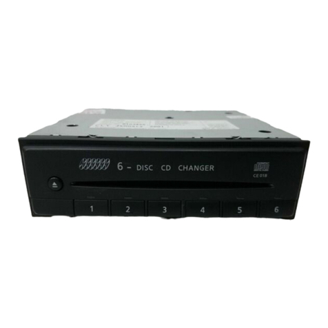
Clarion CDC6300 User manual

FM:-MPX/MW/LW
CD
PLAYER
WITH
VF
DECODER
Owner’s
Guide
LECTEUR
DE
CD-TUNER
FM-MPX/PO/GO
AVEC
DECODEUR
VF
CDC6300
Ce
errr
reir
err
irrrr
irri
rr
ert
tte
enn
en
sense
ence
cencenannonncneuconsensonnonans
1.
2.
3.
4.
5.
6.
.
PRECAUTIONS
DE
MANIPULATION
.
DEPISTAGE
DES
PANNES
PARWN
4
.
WICHTIGE
HINWEISE
ZUR
BETRIEBSSICHERHEIT
.
BESCHREIBUNG
DER
BEDIENUNGSELEMENTE
UND
FUNKTIONEN
.
HANDHABUNG
VON
CD-PLATTEN
.
VORSICHT
BEI
DER
HANDHABUNG
DES
GERATS
.
HILFE
BEI
DER
FEHLERSUCHE
.
ANSCHLUSS
DER
KABEL
Oohond
+
OOP
aN”
Manuel
de
Putilisateur
1.
VOORZORGSMAATREGELEN
.........cesceeeeseeeeeeseens
@
2.
NAAM
EN
FUNKTIES
VAN
DE
BEDIENINGSORGANEN
.............
@
3,
HANTEREN
KOMPAKT
DISKS
.........ccceseseeseeseseeeeeeee
33)
4,
WAARSCHUWING
BIJ
HET
HANTEREN
...........c00000
®
5,
IN
GEVAL
VAN
PROBLEMEN
...........ccscsssesesseeseners
®
G;
BEDRADING:
sec
do2scdectscatencctvecsecctuncpunsvoctarsounterstsbasts
@
Ass
PRECAUCIONES..
cc
c.secinccitvacensinsetccascveisenledacauestites
@
2.
NOMBRE
DE
CONTROLES
Y
FUNCIONES
............504
®
3.
MANEJO
DE
COMPACT
DISCS
.........cssscsssseeseseesees
)
4,
PRECAUCIONES
EN
EL
MANEWO
.........cccssssseseseenees
0
5,
SOLUCION
DE
PROBLEMAS
...........::sscsecsesesssesnesees
@
6.
CONEXIONES
DE
CABLES
...........cssesssssesesssenenterees
@
ti
FORBEREDECSER
sieseinizccnssnsrensesianinestsrineesuninicg
@
2.
NAMN
PA
KONTROLLER
OCH
FUNKTIONER
............
®
3.
NAR
DU
HANDSKAS
MED
CD-SKIVOR
.........0c0se00
rt)
4,
FORSIKTIGHETSATGARDER
.........::scsessessssseseeeerees
®
BPEL
SOW
NING
cadences
aiad
ant
ivagscnseduasavecasahradigeaplet
tes
7)
6.
KABELANSLUTNING
..........cscssssesesseesssnssssesseeeeeeees
©
DN.
PRE
CAU
GOES
sc
csconiatecs
cds set
vies
sesaenseinrac
Pussies
teens
®
2.
NOME
DOS
CONTROLES
E
FUNCOES
.........0cccen
@
3.
MANUSEIO
DO
DISCO
COMPACTO
.........ssscsseseseeees
@
4,
CUIDADO
NO
MANUSEIO
.......ccsseeeeeteeenerieeene
@
5.
ELIMINAGAO
DE
DIFICULDADES.
............sssssssseseeees
®
G.
LIGACOES
DE
FIOS:
io
cicsc
cess
tsisscattncssssiecassiattncstuns
®.
7.
INSTALLATION/INSTALLATION
........cccscsseesseereeseeseeseees
®
8.
SPECIFICATIONS/SPECIFICATIONS
.......cecessseeseeeeeenee
©
9,
FEATURES/CARACTERISTIQUES
..............
weno
cgoueseonsuccaat
@
SP
ae
CLASS
1
LASER
PRODUCT
CAUTION
-
INVISIBLE
LASER
RADIATION
WHEN
OPEN
ANO
INTERLOCKS
DEFEATED.
AVOID
EXPOSURE
TO
BEAM.
VORSICHT!
UNSICHTBARE
LASERSTRAHLUNG
TAITT
AUS.
Seite
DEcKEL
GSOresieT
UND
wee
Sic
ING
UBERBRUCKT
IST
NichT
Oem
stman
1S)
‘AUSSETZEN
YANG
NAR
DENA
DEL
ARU
WIG
VED
ABRING
NAR
meen
Ut
F
FUNCTION
UNOGA
UDSATTELSE
FOR
STRAL
CAUTIONS:
This
appliance
contains
a
laser
system
and
is
classified
as
a
“CLASS
1
LASER
PRODUCT".
To
use
this
model
properly,
read
this
Owner's
Manual
carefully
and
keep
this
manual
for
your
future
reference.
In
case
of
any
trouble
with
this
player,
please
contact
your
nearest
“AUTHORIZED
service
station”.
To
pre-
vent
direct
exposure
to
the
laser
beam,
do
not
try
to
open
the
enclosure.
ADVARSEL
Denne
meerking
er
anbragt
udvendigt
pa
apparatet
og
indiker-
er,
at
apparatet
arbejder
med
laserstraler
af
klasse
1,
hvilket
betyder,
at
der
anvendes
laserstraler
af
svageste
klasse,
og
at
man
ikke
pa
apparatets
yderside
kan
blive
udsat
for
utilladelig
kraftig
straling.
APPARATET
BOR
KUN
ABNES
AF
FAGFOLK
MED
SARLIGT
KENDSKAB
TIL
APPARATER
MED
LASERSTRALER!.
Indvendigt
i
apparatet
er
anbragt
den
her
gengivne
advarsels-
maekning,
som
advarer
imod
at
foretage
sadanne
indgreb
i
apparatet,
at
man
kan
komme
til
at
udseette
sig
for
laserstral-
ing.
OBS!
Apparaten
innehaller
laserkomponent
som
avger
laserstralning
6verstigande
gransen
fdr
laserklass
1.
VAROITUS.
Suojakoteloa
si
saa
avata.
Laite
sisaltaa
laser-
diodin,
joka
lahettaa
nakymaténta
silmille
vaarallista
lasersateilya.
CAUTION
USE
OF
CONTROLS
OR
ADJUSTMENTS
OR
PERFORMANCE
OF
PROCEDURES
OTHER
THAN
THOSE
SPECIFIED
IN
THE
OWNER’S
MANUAL
MAY
RESULT
IN
HAZARDOUS
RADIA-
TION
EXPOSURE.

10.
.
Please
read
this
manual
carefully
before
proceeding
with
installa-
tion.
.
Make
sure
all
of
the.
mounting
hardware
is
complete
before
you
in-
stall
the
CDC6300.
.
It
is
recommended
that
you
remove
the
negative
(—)
terminal
from
the
car
battery
before
you
install
the
CDC6300.
This
will
prevent
accidental
short
circuiting
during
installation.
.
lf
you
have
to
do
any
work
on
the
car
body,
such
as
drilling
holes,
etc.,
consult
your
car
dealer
beforehand.
.
Do
not
open
the
CDC6300’s
case.
There
are
no
user
serviceable
parts
inside.
If
you
drop
anything
into
the
set
during
installation,
consult
your
nearest
CLARION
dealer
or’
an
authorised
CLARION
service
centre.
.
Never
clean
the
surface
of
the
CDC6300
with
chemical
solvents,
as
this
could
damage
the
finish.
Use
a
clean
dry
cloth.
.
If
a
fuse
has
blown,
check
whether
the
CDC6300
is
connected
.cor-
rectly
and
the
car's-electrical
system
is
operating
properly.
Replace
the
fuse
only
with
the
designated
type.
If
the
fuse
blows
again,
con-
tact
you
nearest
CLARION
dealer
or
an
authorised
CLARION
service
centre.
.
If
the
car
is
parked
for
a
long
time
in
the
sun
during
summer
or
in
a
cold
location
during
winter,
the
temperature
inside
the
car
will
reach
extreme
levels.
As
the
unit
may
not
function
properly
in
such
a
case,
use
it
only
after
the
ambient
temperature
has
returned
to
normal.
e@
To
protect
the
semiconductor
laser
from
damage,
the
CD
player
will
automatically
terminate
disc
play
if
its
internal
temperature
rises
past
a
standard
level.
When
this
occurs,
HHHH
will
appear
on
the
display
to
indicate
that
the
standard
level
has
been
ex-
ceeded.
Eject
the
disc
from
the
unit
using
the
eject
button
and
wait
until
the
temperature
returns
to
normal.
(Note
that
the
disc
should
be
removed
from
the
player
for
protection.)
.
8-cm
Single
CDs
Avoid
driving
with
an
8-cm
single
Compact
Disc
in
the
eject
condi-
tion
since
vibrations
may
cause
the
disc
to
fall
out.
Avoid
storing
compact.discs
in
places
which
may
easily
reach
high
temperatures
(such
as
the
dashboard,
rear
tray,
or
seat).
11.
12.
13.
Condensation
When
the
inside
of
the
car
is
very
cold
and
the
player
is
used
soon
after
switching
on
the
heater,
dew
may
form
on
the
disc
or
the
optic-
al
parts
of
the
player
and
proper
playback
may
not
be
possible.
If
dew
forms
on
the
disc,
wipe
it
with
a
soft
cloth.
If
dew
forms
on
the
optical
parts
of
the
player,
do
not
use
the
player
for
about
one
hour
and
the
condensation
will
disappear
naturally
to
allow
normal
op-
eration.
Driving
on
bumpy
roads
which
cause
severe
vibration
may
cause
the
sound
to
jump.
—
In
the
unlikely
event
that
a
problem
arises
with
this
player,
do
not
open
the
case
and
disassemble
or
lubricate
the
rotating
parts
since
the
player
uses
a
precision
mechanism.

2-1.
GENERAL
@
Up
Button
(A
FRONT/RIGHT)
@)
Eject
Button
(
4)
SLIDE
QUT
CHAS
@)
Down
Button
(
“
LEFT/REAR)
7]
————
|
OVERSAMPLING
OIGITAL
FILTER/
DUAL
1
BIT
DAC
t
AB
ST
t
FMi
FM2.
FM3
Rom
Tym
PCH
G8"
2
ee
©
manu
UW
VF
SK
DX
MUTE
LD
DISPLAY
@)
Power
Switch
(©)
Loudness
Selector
Button
(LOUD)
©
Audio
Muting
Button
(MUTE)
@
DISPLAY
®
Loudness
Indicator
(LD)
Message
Display
Area:
Volume,
Balance,
Bass,
Treble,
Fader,
Phone
Mute
@
Audio
Muting
Indicator
(MUTE)
@)
Audio
Mode
Button
(A-M)
DISPLAY
()
CATS
Indicators,
DISC
IN
Indicator
and
RESET
Switch
Tuning
Mode
Selector
Button
(T.
MODE)
@)
Display
Mode
Selector
Button
(DISPLAY)

~
i
THEFT
PREVENTION
CATS
III
(Computer
Anti-Theft
System
TI)
The
CATS
III
system
incorporated
in
your
car
stereo
is
designed
to
minimise
chances
of
theft.
The
CATS
code
has
not
been
input
yet
at
the
time
of
delivery,
so
the
unit
works
as
a
conventional
car
stereo.
Therefore,
you
must
input
an
arbitrary
4-digit
CATS
code
following
installation.
After
the
CATS
code
is
input,
the
unit
will
continue
to
operate
normally
unless
it
is
removed
or
the
power
to
the
unit
is
interrupted.
After
sending
the
unit
or
the
car
for
servicing,
you
will
have
to
input
your
CATS
code
in
order
to
operate
the
unit.
If
a
wrong
CATS
code
is
input,
operation
will
not
be
possible
for
approx.
15
seconds.
If
six
consecutive
mistakes
are
made,
the
wait-
ing
period
will
become
15
minutes
between
each
incorrect
entry.
1.
Be
sure
to
record
your
CATS
code
and
other
data
on
the
RADIO
PASS
Card.
You
will
have
to
show
the
RADIO
PASS
card
when
bring-
ing
your
unit
in
for
servicing
(see
“Servicing”).
Keep
your
RADIO
PASS
card
in
a
place
away
from
the
car
stereo.
2.
You
must
let
thieves
know
that
your
unit
is
protected
by
CATS
by
putting
the
stickers
(supplied
with
your
unit)
on
your
car
windows.
Operation
[1]
Entering
the
CATS
Code
1.
If
the
power
is
turned
on,
press
the
Power
Switch
(@
to
turn
the
unit
off.
2.
Press
the
T.MODE
button
@),
and
while
keeping
it
pressed,
press
the
Power
switch
(@)
to
turn
on
the
power.
This
will
enable
input
of
the
CATS
code.
Digital
Display
n
mon
“0000”
starts
blinking
on
the
display.
Lut
tt
bt
3.
Input
an
arbitrary
4-digit
number
using
the
Preset
buttons
(1
to
5)
40.
(Example)
Input
1-2-3-4
aT
Li
Be
aa
ca
=
“0000”
starts
blinking
again.
4.
Input
the
same
four
digits
again.
(Example)
Input
1-2-3-4
te
say
When
the
second
input
of
the
CATS
code
has
been
correctly
done,
the
CATS
code
is
registered.
The
unit's
power
turns
on
after
“CODE”
appears
on
the
display.
Notes:
1.
Do
not
forget
your
CATS
code.
In
the
event
that
you
lose
your
RADIO
PASS
card
and
forget
your
CATS
code,
your
dealer
can
send
the
unit
to
the
factory
to
have
the
CATS
code
erased;
but
only
if
you
can
prove
you
are
the
rightful
owner
of
the
unit.
2.
In
case
you
have
input
a
wrong
4-digit
code
in
step
3:
If,
for
example
you
input
2-2-3-4
instead
of
1-2-3-4,
input
any
4-digit
number
other
than
2-2-3-4
in
step
4.
The
unit
will
then
return
to
the
condition
in
step
2,
where
“0000”
blinks
on
the
display.
Continue
by
keying
in
the
correct
CATS
code.
3.
If
the
input
numbers
in
step
3
and
4
do
not
match:
If
you
input,
for
example,
1-2-3-4
in
step
3
and
then
2-2-3-4
in
step
4,
the
unit
will
return
to
its
original
condition.
Continue
with
steps
3
and
4,
4.
In
case
you
realise
your
mistake
before
entering
all
4
digits
in
step
3
or
4,
enter
any
digits
to
complete
the
entry.
Then
proceed
as
ex-
plained
in
notes
2
or
3
above.
Proceed
in
the
same
way
to
correct
input
mistakes
made
during
[2]
Releasing
CATS
or
[3]
Erasing
and
Changing
the
CATS
Code.
[2]
Releasing
the
CATS
Code
(when
you
have
removed
the
car
stereo
or
sent
the
car
for
servicing)
1.
Turn
the
power
on
by
pressing
the
Power
switch
(a).
Digital
Display
MMM
“0000”
starts
blinking
on
the
display.
Lt
Gt
2.
Input
your
CATS
code.
(
|
(Example)
Input
1-2-3-4
te
a4

i
Erasing
and
Changing
the
CATS
Code
.
If
the
power
is
turned
on,
press
the
Power
Switch
@
to
turn
the
unit
off.
2.
Press
the
T.MODE
button
(@),
and
while
keeping
it
down,
press
the
Power
switch
(@
to
turn
on
the
power.
Digital
Display
aor
“0000”
starts
blinking
on
the
display.
i
3.
Input
your
CATS
code.
The
CATS
code
has
now
been
erased,
and
the
unit
will
operate
normally.
c
4
4
To
input
a
new
CATS
code,
follow
-
the
steps
in
[1]
Entering
the
CATS
Code.
When
the
erasure
of
the
CATS
code
has
been
completed,
the
power
to
the
unit
will
be
switched
on.
Note:
In
case
you
input
a
wrong
CATS
code
in
step
3,
you
must
wait
for
15
seconds
before
the
unit
accepts
a
new
code.
In
this
case,
return
to
“[2]
Releasing
the
CATS
Code”,
then
input
the
correct
CATS
number
as
explained
in
[2]
2.,
operate
the
unit,
then
per-
form
the
steps
in
“[3]
Erasing
and
Changing
the
CATS
Code”.
Servicing
Should
your
car
stereo
malfunction,
fill
in
the
RADIO
PASS
card
and
bring
it
to
the
repair
shop
together
with
the
unit.
You
may
also
erase
the
CATS
code
yourself
as
explained
in
[3]
Erasing
and
Changing
the
CATS
Code,
and
then
bring
in
the
unit
for
servicing.
@
CATS
INDICATOR
As
an
added
measure
against
theft,
you
can
make
the
indicator
@
flash
to
alert
thieves
of
an
active
theft-prevention
system.
Pressing
the
Eject
button
(
4
)
@
for
2
seconds
or
longer
when
the
power
is
off
will
cause
the
DISC
IN
indicator
©
to
start
flashing.
Repeat
this
procedure
to
make
the
indicator
stop
flashing.
SLIDE
OUT
CHASSIS
@
GENERAL
CAUTION:
Turning
the
ignition
on
or
the
Power
switch
@)
on
when
the
volume
control
is
set
to
maximum
or
a
very
high
level
may
cause
damage
to
your
hearing.
*%
Power
Switch
e
(4)
Press
once
to
turn
on
the
power.
The
illumination
will
light.
Press
once
more
to
turn
off
the
power.
%
Audio
Mode
Button
(A-M)
ss
@)
The
audio
mode
is
normally
set
to
the
VOL
(volume)
control
mode.
Press
this
button
to
select
another
audio
mode.
The
audio
mode
switches
in
the
order
BASS,
TRE
(Treble),
BAL
(left/right
balance),
FAD
(front/rear.
fader)
and
then
back
to
VOL.
The
selected
mode
is
indicated
on
the
display.
%
Up
Button
(~
FRONT/RIGHT)
se
G)
Down
Button
(Vv
LEFT/REAR)
ss
(@)
Use
these
buttons
to
adjust
the
level
or
balance
of
the
selected
au-
dio
mode.
(See
page
7.)
:
*
Audio
Muting
Button
(MUTE)
#-
6),
@
Press
this
button
to
mute
audio
output.
The
“MUTE”
indicator
will
flash.
Press
once
more
to
release
muting
and
restore
the
sound
volume
to
the
original
level.
%
Loudness
Selector
Button
(LOUD)
=
6),
©
Press
this
button
to
emphasize
low
and
high
frequency
‘sounds
when
listening
at
low
or
medium
levels.
The
“LD”
indicator
will
light
and you
will
get
a
more
powerful
sound.
Press
once
more
to
turn
off
loudness.
%*
Switching
the
illumination
colour
=
(7),
The
illumination
colour.
of
the
set
can
be
switched
by
keeping
the
Display
Mode
Selector
Button
()
pressed
and
pressing
the
Tuning
Mode
Selector
Button
@).
Each
time
the
Tuning
Mode
Selector
But-
ton
@)
is
pressed,
the
illumination
will
alternate
between
amber
and
green.
%
Triggered
phone
mute
(for
use
with
a
cellular
phone)
When
a
call
is
received
on
the
cellular
phone,
the
“TEL”
indicator
lights
and
sound
from
the
CDC6300
is
muted.
CD
play
will
pause
while
“TEL”
is
displayed.
When
the
phone
is
hung
up,
the
previous
operation
resumes.

m@
AUDIO
MODE
DISPLAY
AND
OPERATIONS
Centre
Position
(flat
response)
Operation
VOL
When
the
numerical
value
decreases,
the
volume
level
is
volume
lowered;
when
the
numerical
value
increases,
the
level
goes
control
up.
BASS
(
bass
’
A
negative
value
indicates
a
bass
cut
while
a
positive
one
control
indicates
a
bass
boost.
(Adjustment
range
is
—7
to
7.)
TREB
—_
(
treble
A
negative
value
indicates
a
treble
cut
while
a
positive
one
control
indicates
a
treble
boost.
(Adjustment
range
is
—7
to
7.)
BAL
:
“BO”
indicates
equal
volume
levels
in
both
channels.
When
left/right
the
“BL”
value
increases
the
volume
in
the
left
channel
balance
increases,
and.
if
the
“BR”
value
increases
the
volume
in
the
control
right
channel
increases.
“FO”
indicates
equal
volume
levels
in
the
front
and
rear
speakers.
When
the
“FR”
value
increases
the
volume
in
the
FAD
rear
speakers
increases,
and
if
the
“FF”
value
increases
the
front/rear
volume
in
the
front
speakers
increases.
fader
(Only
applicable
for
a
4-speaker
system
using
the
LINE-OUT
control
terminals.)
e
The
built-in
amplifier
is
for
front
speaker
driving
only.
When
using
this
unit
alone,
connect
it
to
the
front
speakers.
‘
:
Note
1:
Inthe
BAL
and
FAD
modes,
the
control
steps
will
not
correspond
to
the
indicated
values
because
of
the
large
number
of
steps.
Note
2:
After
adjusting
the
audio
modes
as
required,
press
the
Display
Mode
Selector
Button
(@)
to
return
to
the
original
display.
Note
3:
Or,
the
display
will
automatically
return
to
the
original
setting
in
five
seconds
if
no
key
is
pressed.

2-2.
CD
SECTION
@)
Top
Button
(TOP)
—
@§
Intro
Scan
Button
(SCN)
@)
Eject
Button
(
#)
@®
Disc
Insertion
Slot
@)
CATS
Indicators,
DISC
IN
Indicator
and
RESET
Switch
DISPLAY
ee
we
(eer
Cee
ees
Aner
a
B
“TW
FMT
Fa
FAG
pom
Ze
SK
DX
ST
(fh
BOA
sey
:
@3
Track
Search
and
Manual
Search
Button
(Forward
Direction)(
A)
8
TIMES
OVERSAMPLING
DIGITAL
FILTER/DUAL
1
BIT
DAC
@)
Track
Repeat
Button
(RPT)
@4
Track
Search
and
Manual
Search
Button
(Reverse
Direction)(
¥
)
mute
ip
4
@
Random
Play
Button
(RDM)
@2
CD
Mode
Selector
Button
(©
)
@
Display
Mode
Selector
Button
(DISPLAY)
‘DISPLAY
@)
Running
Indicator
@
Random
Play
Indicator
(RDM)
@)
Intro
Scan
Indicator
(SCN)
©
CD
Mode
Indicator
(©
)
@
Message
Display
Area:
Track
Number,
Playing
Time
@
Track
Repeat
Indicator
(@>)

-
@
CD
SECTION
*%
Playback
1.
Turn
the
power
on.
pressing
the
Power
switch
@.
=
@)
2.
Hold
the
Compact
Disc
with
the
label
facing
up
and
insert
it
into
the
Disc
Insertion
Slot.
When
the
disc
is
inserted
about
half-way,
the
auto
loading
mechanism
takes
over
and
loads
the
disc
cor-
rectly.
=
@,
@
3.
Once
the
disc
has
been
loaded,
the
DISC
IN
indicator
@)
and
the
CD
Mode
indicator
(
©
)
©
light
and
playback
will
start
from
track
no.
1.
The
Running
indicator
@
will
move
from.
left
to
right
to
indicate
CD
play
is
in
progress.
=
G),
©,
®
Note:
Check
whether
the
DISC
IN
indicator
is
lit
before
inserting
a
CD.
If
a
CD
is
already
loaded,
forcing
a
new
CD
into
the
slot
can
scratch
the
disc
and
damage
the
set.
@
Operation
*
Eject
Button
(
4
)
=
@)
Press
this
button
during
playback
or
when
a
disc
is
loaded
to
eject
the
CD.
Notes:
1.
Pressing
the
CD
Mode
Selector
Button
43
or
pushing
the
CD
after
it
has
been
ejected
will
cause
the
disc
to
be
loaded
and
played
back
again.
2.
Once
the
CD
is
ejected,
be
sure
to
remove
it
from
the
Disc
Inser-
tion
Slot
within
15
seconds.
Otherwise
it
will
reload
automatically
to
protect
it
from
damage.
Disc
play
will
not
start
in
this
case,
however.
3.
When
using
8-cm
CD
singles,
the
CD
cannot
be
loaded
by
press-
ing
the
CD
Mode
Selector
Button
42
and
the
auto
reloading
func-
tion,
described
above,
will
not
work.
*
CD
Mode
Selector
Button
(
©
)
=
4
1.
Press
this
button
when
you
want
to
switch
from
the
Tuner
mode
to
the
CD
mode.
.
If
this
button
is
pressed
during
CD
playback,
playback
will
pause.
Press
the
button
once
more
to
release
the
pause
mode
and
con-
tinue
CD
playback.
*
Track
Search
and
Manual
Search
Buttons
1.
Forward
Direction
(
A
)
=
(3
Each
time
this
button
is
pressed
during
playback,
the
track
num-
ber
on
the
display
will
increase
by
one
(track
search).
Keeping
the
button
pressed,
playback
will
speed
up
for
quick
search
to
a
de-
sired
point
in
the
track
(manual
search).
If
the
button
is
kept
pressed
for
5
seconds
or
more,
the
CD
is
played
back
at
15
times
the
normal
playback.
speed.
2.
Reverse
Direction
(
¥
)
=
@4
Each
time
this
button
is
pressed
during
playback,
the
track
num-
ber
on
the
display
will
decrease
by
one
(track
search).
Keeping
the
button
pressed,
the
track
will
be
played
quickly
in
reverse
for
quick
search
to
a
desired
point
in
the
track
(manual
search).
If
the
button
is
kept
pressed
for
5
seconds
or
more,
the
CD
is
played
back
in
reverse
at
15
times
the
normal
playback
speed.
*
Track
Repeat
Button
(RPT)
»=
(5,
®
Press
this
button
to
play
a
eae
repeatedly.
When
the
button
is
pressed
during
CD
playback,
‘
lights
on
the
display
and
the
track
currently
playing
is
slevedr
repeatedly.
To
cancel
repeat
play-
back,
press
the
button
once
more.
The
“e>”
indicator
goes
out
and
normal
playback
resumes.
-Intro
Scan
Button
(SCN)
ss
®,
@)
Use
this
button
to
find
a
certain
track
on
the
CD.
When
the
button
is
pressed,
the
“SCN”
indicator
@
lights
and
the
first
10
seconds
of
each
track
are
played.
To
stop
Intro
Scan
operation,
press
this
but-
ton
once
more.
The
“SCN”
indicator
goes
out
and
normal
playback
resumes.
;
Top
Button
(TOP)
ss
(7
Use
this
button
to
start
playback
from
the
BesinninG
of
the
CD.
When
pressed,
playback
will
start
over
from
the
beginning
of
track
1.
Random
Play
Button
(RDM)
es
(3,
@
When
this
button
is
pressed
during
CD
playback,
the
“RDM”
indi-
cator
@
lights
and
the
tracks
on
the
CD
will
be
played
back
in
a
random
order,
generated
by
the
built-in
microprocessor.
To
cancel
random
playback,
press
this
button
once
more.
The
“RDM”
indi-
cator
goes
out
and
normal
playback
resumes.
Display
Mode
Selector
Button
(DISPLAY)
m=
@,
@
Use
this
button
to
select
between
display
of
track
numbers
or
the
playing
time.
'
Playing
time
display
Track
number
display
-

2-3.
RADIO
SECTION
Preset
Buttons
(1-5)
@)
Preset
Scan
and
Auto
Store
Button
(PS/AS)
|
DISPLAY
@3
Up
Tuning
Button
(f)
S
TIMES
OVEASAMPLING
DIGITAL
FILTER/DUAL
18IT
DAC
M
FM?
FPM2
FM3
RDM
‘
o
Pcn
4
Down
Tuning
Button
(
¥
)
(DE-O8
Tuner
Mode
Selector
Button
(vw)
@)
Band
Selector
Button
(BAND)
@
Traffic
Information
Button
(VF)
Tuning
Mode
Selector
Button
(T.MODE)
d
|
@
DISPLAY
|
@
Manual
Tuning
Indicator
(MANU)
@
VF
Indicator
(VF)
@
Tuner
Mode
Indicator
(vw)
@
LW
Band
Indicator
(L)
@)
MW
Band
Indicator
(M)
—@
FM
Band
Indicators
(FM1,
FM2,
FM3)
(®)
Preset
Channel
Display
@)
SK
Indicator
(SK)
@
DX
Indicator
(DX)
(©)
Frequency
Display
(kK)
Stereo
Reception
indicator

@
RADIO
SECTION
@
Operation
*
Tuner
Mode
Selector
Button
(vv)
=
49,
©,
©,
@
Press
this
button
to
switch
from
the
CD
mode
to
the
Tuner
mode.
When
this
button
is
pressed,
the
Tuner
Mode
indicator
(vw),
one
of
the
Band
indicators
(jmmm)
and
the
frequency
light,
and
radio
broad-
casts
can
be
listened
to.
:
*
Band
Selector
Button
(BAND)
#*
@0,
@)
Press
this
button
to
switch
to
another
reception
band.
Each
time
this
button
is
pressed,
the
reception
band
changes
in
the
following
order:
FM1
—>
FM2
—
FM3
—
LW/MW
-—
FM1,
etc.
The
selected
band
can
be
confirmed
with
a
quick
glance
at
the
dis-
play.
Four
square
dots
(mmmm)
will
light
above
the
Band
indicator
corresponding
to
the
band
you
are
listening
to.
The
frequency
being
received
is
displayed
here.
The
frequency
is
displayed
in
units
of
kHz
for
the
LW/MW
bands
and
MHz
for
the
FM
band.
LW
band
selected
Note:
FM1,
FM2
and
FM3
covers
the
same
band.
%
Tuning
Mode
Selector
Button
(T.MODE)
»=-
(8),
@
Press
this
button
to
select
the
tuning
mode.
If
the
“MANU”
indicator
lights
when
this
button
is
pressed,
the
Manual
Tuning
mode
is
set.
If
the
“MANU”
indicator
does
not
light,
the
Seek
Tuning
mode
is
set.
%
Up/Down
Tuning
Buttons
(A,
¥
)
=
©,
@,
4,
©,
©
e
Manual
Tuning
Press
the
Tuning
Mode
Selector
button
(8)
so
that
“MANU”
lights.
-
on
the
display.
Press
the
Up
Tuning
button
@
to
increase
the
displayed
frequen-
cy
or
press
the
Down
Tuning
button
(4
to
decrease
the
frequency.
The
frequency
changes
in
steps
of
50
kHz
on
the
FM
band,
9
kHz
on
MW
and
1
kHz
on
LW.
Keeping
one
of
the
buttons
pressed
will
change
the
frequency
continuously.
e
Seek
Tuning
(DX/Local)
=
@),
43, (4,
D,
@®,
©
Use
this
mode
to
search
for
broadcasting
stations.
Press
the
Tuning
Mode
Selector
button
(8)
so
that
“MANU”
goes
out
on
the
display.
Press
the
Up
Tuning
button
@3
or
Down
Tun-
ing
button
44
to
seek
for
a
station
broadcasting
at
a
higher
or
lower
frequency
on
the
selected
band.
When
a
station
is
found,
seek
tuning
stops.
During
seek
tuning,
the
frequency
changes
in
steps
of
50
kHz
on
the
FM
band,
9
kHz
on
MW
and
7
kHz
on
LW.
Keeping
the
Tuning
Mode
Selector
button
pressed
for
more
than
2
seconds,
the
set
will
switch
between
DX
and
Local
sensi-
tivity.
When
the
DX
mode
is
set
(“DX”
indicator
@
lit),
seek
tuning
will
stop
whenever
a
station
is
found.
When
local
sensitivity
is
set
(“DX”
indicator
@
not
lit),
seek
tuning
will
only
tune
in
stations
with
strong
signals,
in
other
words
stations
broadcast
from
local
transmitters.
,
%
Preset
Scan
and
Auto
Store
Button
(PS/AS)
»©
(0,
20,
2),
@,
®,
@
Aute
Store:
Pressing
this
button
for
more
than
two
seconds,
up
to
five
strong
stations
in
the
area
are
stored
on
the
five
presets
for
the
selected
band.
Auto
Store
is
convenient
when
driving
away
from
home
when
you
do
not
know
the
frequency
assign-
ment
of
local
stations..
Preset
Scan:
Pressing
the
switch
for
less
than
two
seconds,
the
pre-
—
set
stations
on
the
selected
band
are
scanned.
‘In
this
way
you
can
quickly
decide
on
which
station
of
the
preset
ones
you
want
to
listen
to.
e
Auto
Store
(AS)
1.
Select
the
desired
band
by
pressing
the
BAND
Selector
button
2.
Press
the
PS/AS
button
@)
for
two
seconds
or
more
to
store
up
to
five
strong
stations
in
the
area
on
the
selected
band.

Notes:
3.
To
stop
Auto
Store
operation,
press
the
PS/AS
button
@)
once
more.
Notes:
;
1.
When
using
Auto
Store
on
an
FM
band,
when
all
five
presets
for
that
band
have
been
preset,
the
set
will
NOT
switch
to
another
FM
band.
2.
Auto
Store
stops
if
fewer
than
five
stations
with
sufficiently
strong
signals
are
found
on
the
band.
3.
Any
previous
stations
memorised
on
the
band
will
be
erased
as
new
ones
are
stored
in
memory.
i
Scan
(PS)
.
Select
the
desired
band
by
pressing
the
BAND
Selector
button
2.
Press
the
PS/AS
button
for
less
than
two
seconds
to
scan
the
preset
stations
on
the
selected
band.
The
preset
stations
will
be
tuned
in
for
five
seconds
each.
During
preset
scanning,
the
frequency
of
the
received
station
and
the
corresponding
preset
channel
number
are
displayed.
1.
When
Preset
Scan
is
used
on
the
FM
band,
the
preset
chan-
nels
on
the
FM1,
FM2,
and
FM3
bands
are
scanned
con-
tinuously
in
order.
2.
If
a
preset
station
is
already
tuned
in,
scanning
will
start
from
the
next
preset
station.
3.
If
the
signal
of
a
preset
station
is
too
weak,
that
station
will
be
skipped
during
Preset
Scan.
4.
To
continue
to
listen
to
a
station,
press
the
PS/AS
button
@)
once
again,
or
press
one
of
preset
buttons
@9
1
to
5.
5.
Be
careful
not
to
press
the
PS/AS
button
for
two
seconds
or
more,
as
this
will
engage
Auto
Store
and
memorised
stations
will
be
erased
as
new
ones
are
being
stored.
*
Presetting
Stations
»F
(0,
(9,
@,
@,
®,
@
With
this
unit,
a
total
of
20
stations
can
be
stored
in
memory,
5
stations
for
each
of
the
LW/MW,
FM1,
FM2
and
FM3
bands.
1.
Press
the
Tuner
Mode
Selector
button
4
@9
to
select
the
tuner
mode
and
select
the
desired
band
(FM1,
FM2,
FM3,
or
LW/MW)
with
the
BAND
selector
button
@.
.
Activate
the
Auto
Store
feature.
(See
Auto
Store
(AS)
above.)
.
In
case
the
Auto
Store
features
fail
to
memorise
up
to
five
station
or
if
you
want
to
preset
stations
with
weak
signals:
1)
Select
the
desired
broadcasting
station
using
the
Manual
Tun-
ing
mode.
(See
Manual
Tuning.)
2)
Keep
the
Preset
button,
on
which
you
want
to
store
the
sta-
tion,
pressed
for
more
than
two
seconds.
The
sound
from
the
.
broadcasting
station
is
muted.
When
you
hear
the
sound
again,
the
station
has
been
stored
in
memory.
*%
Preset
Buttons
(1—5)
»
40,
®
Once
your
favourite
stations
have
been
stored
on
the
Preset
but-
tons,
you
can
tune
into
them
simply
by
pressing
one
of
the
preset
buttons.
The
number
of
the
selected
button
appears
in
the
Preset
Channel
display.
*%
Stereo
Reception
Indicator
(ST)
=
&
The
“ST”
indicator
lights
on
the
display
when
an
FM
station
with
a
strong
signal
broadcasting
in
stereo
is
received.
Note:
The
“ST”
indicator
does
not
light
during
manual
tuning,
seek
tuning,
and
the
Preset
Scan
and
Auto
Store
modes.
The
in-
dicator
lights
only
when
a
station
has
been
properly
tuned
in.
*
Traffic
Information
Button
(VF)
=
@,
©,
@
1.
Traffic
information
broadcasts
are
special
announcements
to
alert
drivers
of
road
blocks,
congestions,
etc.
on
the
roads.
These
broadcasts
are
broadcast
on
major
radio
stations.
(Germany,
Switzerland
and
Austria)
When
the
“SK”
indicator
is
lit,
this
signifies
that
the
station
tuned
in
transmits
traffic
information
broadcasts.
Using
the
VF
button
@2,
you
can
select
automatic
reception
of
Traffic
information
broadcasts
(“VF”
indicator
lit).
This
means
that
if
a
traffic
information
broadcast
is
aired
while
you
listen
to
a
CD,
CD
play
will
pause
and
the
announcement
can
be
heard.
When
the
announcement
is
completed,
CD
playback
continues.
Traffic
Information
announcements
are
reproduced
at
a
preset
volume
level
and
can
be
heard
even
if
the
volume
level
is
set
to
minimum.
“INFO”
appears
on
the
display
during
reception
of
traffic
in-
formation
broadcasts.
2.
If
the
VF
button
@
is
pressed
while
a
station
not
broadcasting
traffic
information
is
being
received,
the
unit
will
search
for
a
sta-
tion
broadcasting
such
information
and
tune
into
it
if
possible.
3.
If
the
“VF”
indicator
lights
during
Seek
Tuning
or
Auto
Store,
only
stations
broadcasting
Traffic
Information
will
be
heard
or
stored
in
memory.

Traffic
Information
Transmitter
a.
toe
1.
/"s
“oon
98.0
[ea
%
Retuning
of
Traffic
Information
Stations
(only
valid
when
VF
is
on)
=~
2
When
the
signal
from
the
station
broadcasting
traffic
information
becomes
too
weak,
the
unit
will
search
for
another
station
broad-
casting
such
information.
Auto
Search
for
Traffic
Information
Transmitters
%
Adjusting
the
Volume
of
Traffic
Information
Announcement
=
3),
@,@,
©
The
volume
level
for
traffic
information
announcements
has
been
preset
at
the
factory.
It
is
possible
to
change
this
level
if
required.
1.
Tune
in
the
traffic
information
station
broadcasting
the
strongest
signal
you
can
find.
2.
Keep
the
VF
button
@
pressed
for
2
seconds.
“VF18”
will
be
dis-
played.
3.
Use
the
Up
button
@)
and
Down
button
@
to
change
the
volume
level
of
traffic
information
announcements.
The
minimum
level
is
13
and
maximum
level
23.
4.
Once
a
suitable
level
has
been
set,
press
the
VF
button
@)
once
more
to
return
to
normal
operation.

This
unit
has
been
designed
specifically
for
playing
compact
discs
bear-
ing
the
“gis”
mark.
Siewtal
Avia
No
other
discs
can
be
played.
To
remove
the
compact
disc
from
its
storage
case,
press
down
on
the
centre
of
the
case
and
lift
the
disc
out,
holding
it
carefully
by
the
edges.
Removing
the
disc
Proper
way
to
hold
°
the
compact
disc
You
should
wipe
any
fingermarks
and
dust
off
with
a
soft
cloth,
wiping
in
a
straight
motion
from
the
centre
of
the
compact
disc
to
the
outside.
m@
NOTE
ON
COMPACT
DISCS
Never
stick
labels
on
the
surface
of
the
compact
disc
or
mark
the
sur-
face
with
a
pencil
or
pen.
Do
not
use
any
solvents
such
as
commercially
available
cleaners,
anti-
static
spray,
or
thinner
to
clean
the
compact
disc.
:
Do
not
insert
a
compact
disc
with
serious
scratches,
or
CDs
that
are
deformed
or
faulty
as
this
can
result
in.
malfunction
or
even
damage
to
the
unit.

7
Pay
close
attention
to
these
cautions
BEFORE
removing
m@
PROCEDURE
FOR
REMOVAL
the
unit
from
its
mounting
bracket
1)
Push
the
release
button.
The
handle
will
spring
forward.
1.
Eject
the
disc
and
turn
the
power
off
before
the
unit
is
removed
2)
Lift
up
the
handle
and
carefully
pull
out
the
unit.
from
the
dash.
2.
Avoid
touching
the
unit’s
heat
sink
immediately
after
use,
since
it
can
be
very
hot.
Heat
Sink
or
Traut
WETARRALTT’
SSSA
SS
Su
SS
SS
SSSSASSSSS
Lift
handle
é
——

PROBLEM
REMEDY
Connect
wires
correctly.
Fuse
blown.
Improper
connection
of
connection
wires.
Incorrect
setting
of
the
Fader
control
mode
(FAD).
If
you
use
a
2-speaker
system,
no
sound
will
be
heard
if
the
Fader
setting
is
to
the
very
rear
(“FR9”
displayed).
In
that
case,
adjust
the
Fader
control
(FAD).
Press
the
Eject
button
(
&
)@.
CD
will
not
load.
ACD
is
already
loaded.
The
CD
is
loaded
upside
down.
CD
loads
but
is
immediately
ejected.
Turn
the
CD
over
and
load
it
again.
Contact
the
store
of
purchase
or
the
nearest
authorised
Clarion
service
centre.
Clean
the
CD
or
play
another
one.
Leave
the
unit
switched
on
for
about
1
hour
to
Jet
the
moisture
evaporate.
Cannot
eject
the
CD.
Malfunction
in
built-in
microcomputer.
Music
skips
or
misses
portions
of
the
The
CD
is
badly
scratched,
warped,
or
defective.
track
being
played.
Poor
sound
reproduction
when
unit
is
Probably
due
to
dew
formation
on
optical
pick-up
or
switched
on.
CD.
Malfunction
of
built-in
microprocessor
due
to
electrical
noise,
etc.
Nothing
happens
when
a
button
is
pressed.
Incorrect
display.
Turn
off
the
Power
switch
or
turn
off
the
ignition
switch
completely.
Press
the
Reset
switch
with
e.g.
a
ballpoint
pen.
RESET
SWITCH

@
This
unit
incorporates
a
variety
of
diagnostic
functions
for
protection
of
the
system.
If
damage
to
the
system
occurs,
an
error
display
will
appear.
Be
sure
to
act
in
accordance
with
the
Recommended
Remedy.
Error
Display
,
Recommended
Remedy
Displayed
in
the
CD
mode.
Temperature
is
too
high.
—Wait
until
the
temperature
has
settled
to
normal.
(See
item
8
under
Precautions
on
page
3.)
Display
in
the
CD
mode.
Indicates
a
malfunction
in
the
CD
mechanism
(e.g.
the
ejecting
and
loading
system
does
not
operate.)
—>The
CD
mechanism
could
have
been
damaged.
Refer
the
problem
to
your
dealer
or
the
nearest
AUTHORISED
Clarion
service
centre.
Displayed
during
CD
playback.
Indicates
pick-up
focus
failure,
which
is
most
likely
due
to
serious
scratches
on
the
CD.
:
—
Check
the
disc
for
scratches.

@
2-speaker
application
67)
li
Systéme
a
2
enceintes
6?)
CDC6300
@
4-speaker
application
2<2-channel
high-power
amplifier
.
@
Systeme
a
4
enceintes
avec
amplificateur
de
puissance
2X2
canaux
69
CDC6300

(See
page
@
)
@)
ANTENNA
@)
FRONT
RIGHT
@
@)
GRAY
(@)
FRONT
RIGHT
©
(6)
GRAY/BLACK
(6)
FRONT
LEFT
©
@)
WHITE
FRONT
LEFT
©
(9)
WHITE/BLACK
ACCESSORY
+12
V
a)
RED
@3
GROUND
@3
BLACK
44
AUTO
ANTENNA
@§
BLUE/WHITE
ILLUMINATION
@)
ORANGE/WHITE
a3
PERMANENT
YELLOW
@o
AMP
REMOTE
(BLUE/WHITE)
@)
Interface
connector
for
desired
car
application
@)
PHONE
MUTE
(to
external
mute
lead
of
cellular
telephone)
@3
BROWN
@4
RCA
LINE
OUTPUT
(GRAY
LEAD)
for
connection
of
external
power
amplifier
@8
RED
(FRONT
RIGHT)
@§
WHITE
(FRONT
LEFT)
@
RCA
LINE
OUTPUT
(BLACK
LEAD)
for
connection
of
external
power
amplifier
RED
(REAR
RIGHT)
@9
WHITE
(REAR
LEFT)
RCA
TERMINAL
EXTENSION
CORD
_
(separately
available)
@)
STEREO
POWER
AMPLIFIER
62
FRONT
LEFT
SPEAKER
@3
FRONT
RIGHT
SPEAKER
REAR
LEFT
SPEAKER
@5
REAR
RIGHT
SPEAKER
EXTENSION
CORD
(separately
available)
6)
2-speaker
application
68
4-speaker
application
2<2-channel
high-power
amplifier
Notes:
2
Cy
1.
4-speaker
application
Use
either
the
front
speaker
leads
(@),
@,
©
and
@)
and
the
RCA
LINE
OUT
terminals
@)
with
a
2-channel
amplifier
or
the
RCA
LINE
OUT
terminals
@4
and
@?
with
a
2X2-channel
amplifier.
2.
Use
speakers
with
an
impedance
of
40
and
input
of
25
W
or
greater.
When
using
an
external
power
amplifier,
please
be
sure
to
use
com-
patible
speakers.
3.
Improper
installation
may
cause
damage
to
your
unit
or
car.
If
you
do
not
have
appropriate
experience,
consult
a
qualified
installer.
4.
For
other
system
applications,
contact
your
dealer
for
details.

Before
proceeding
with
installation:
1)
Remove
the
(—)
terminal
connector
from
the
car
battery.
2)
Use
the
supplied
screws
for
installation.
Other
screws
may
cause
problems.
Chassis
Chassis
Max.
8
mm
3)
Pay
special
attention
when
routing
wires
in
the
car.
Keep
the
wires
at
a
safe
distance
from
the
engine
and
exhaust
system
area
in
the
engine
room.
Extreme
heat
will
damage
the
wires.
Avant
de
procéder
4
|’installation:
:
1)
Enlever
le
connecteur
de
la
borne
(—}
de
la
batterie
de
la
voiture.
Car
battery
Batterie
de
voiture
2)
Utiliser
les
vis
fournies
pour
I‘installation.
D’autres
vis
peuvent
pro-
voquer
des
problémes.
Chassis
Chassis
Damaged
Endommagé
3)
Faire
particuligérement
attention
lors
de
l'acheminement
des
cables
dans
la
voiture.
,
Garder
les
cables
a
une
distance
sire
du
moteur
et
de
la
zone
d‘échappement
de
gaz
dans
le
compartiment
du
moteur.
Une
chaleur
extreme
endommagera
les
cables.
@
Table of contents
Other Clarion CD Player manuals

Clarion
Clarion ProAudio DXZ935 User manual

Clarion
Clarion DCZ625 User manual

Clarion
Clarion DXZ938R User manual

Clarion
Clarion XMD3 User manual

Clarion
Clarion CDC1255Z User manual

Clarion
Clarion XMD3 User manual

Clarion
Clarion CDC605 User manual

Clarion
Clarion ProAudio DXZ535 User manual

Clarion
Clarion DRB4675 User manual

Clarion
Clarion CDC605 User manual

Clarion
Clarion DX515 User manual

Clarion
Clarion DCZ625 User manual

Clarion
Clarion PN-2218I User manual

Clarion
Clarion DRX9255 User manual

Clarion
Clarion DB415 User manual

Clarion
Clarion CDC655Tz User manual

Clarion
Clarion DC6Z5 User manual

Clarion
Clarion PP-2449H-A User manual

Clarion
Clarion drx5375r User manual

Clarion
Clarion CDC635 CDC635 CDC635 User manual