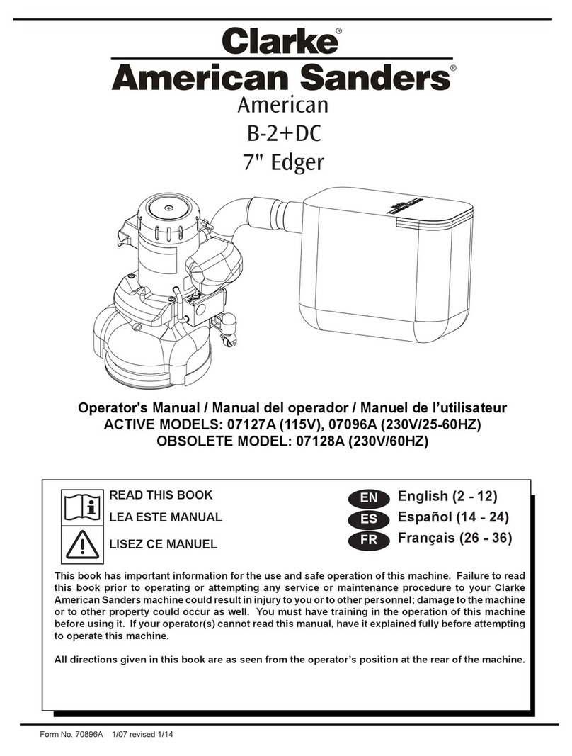
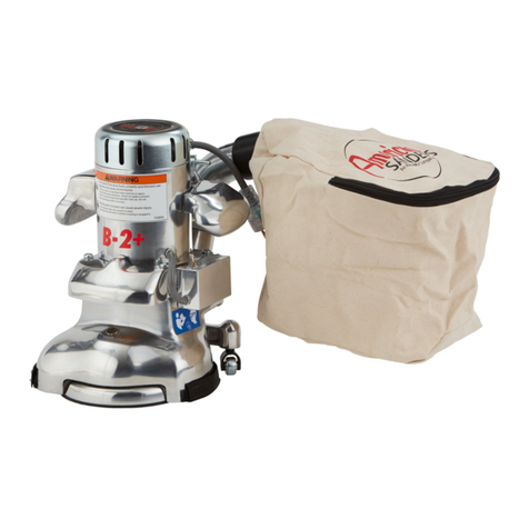
Clarke 07170A User manual

Electronic Service
Manuals
This electronic document is provided as a service to our customers.
Wedonotcreatethecontentsoftheinformationcontainedinthisdocu-
ment. Shouldyouhavedetailedquestionspertainingtotheinformation
contained in this document, you may contact Michco, or the manufac-
turer which provided the original information in this electronic deliver-
able. Michco’sonlypartin this electronic deliverable was the electronic
assemblyprocess. Byprovidingthismanualonlinewearenotguaran-
teeing parts availability.
You may contact Michco through the following methods:
Phone (517) 484-9312 or (800) 331-3339
2011 N. High St. -- Lansing, Michigan -- 48906
Fax: (517) 484-9836
Email: [email protected]
Web site: www.Michco.Com
Parts Web site: www.FloorMachineParts.Com
Order Parts on Line at:
www.FloorMachineParts.Com
Directly to Parts & Service:
By Fax: (517) 702-2041
By Voice: Use numbers above.
Serving the Cleaning Industry Since 1922
Notice: All copyrighted material remains property of original owners, all trademarks are property of respective owners.
ManualsaresubjecttoManufacturer’sreproductionlimitations. Originalsorreproductionswereprovidedbymanufacturers
through a request. We make no warranty as to the correctness of information provided in this document and you assume
allrisk. By placing thesemanualsonlinewe are notdeclaringourcorporation to be anmanufacturerauthorizeddealer or
provider, please check ourwebsiteforauthorizedmanufacturerswerepresent.

Form No. 71376A 6/09 revised 10/10
CE7 PrCE7 Pr
CE7 PrCE7 Pr
CE7 Proo
oo
o, SE7 Pr, SE7 Pr
, SE7 Pr, SE7 Pr
, SE7 Proo
oo
o,,
,,
,
CE7 Pro+ & SE7 Pro+CE7 Pro+ & SE7 Pro+
CE7 Pro+ & SE7 Pro+
EdgersEdgers
EdgersEdgers
Edgers
Operator's Manual
Manual del operador
Manuel de l’utilisateur
Models: 07170A, 07176A, 07180A, 07175A
This book has important information for the use and safe operation of this machine. Failure to read
this book prior to operating or attempting any service or maintenance procedure to your Clarke
AmericanSandersmachinecouldresultininjurytoyouortootherpersonnel;damagetothemachine
or to other property could occur as well. You must have training in the operation of this machine
beforeusingit. Ifyouroperator(s)cannotreadthismanual, have it explained fully before attempting
to operate this machine.
All directions given in this book are as seen from the operator’s position at the rear of the machine.
English (2 - 11)
Español (12 - 21)
Français (22 - 31)
ES
EN
FR
READ THIS BOOK
LEA ESTE MANUAL
LISEZ CE MANUEL

EN
ENGLISH
-2- FORM NO. 71376A - Clarke®American Sanders Operator's Manual (EN) - CE 7 Pro, SE7 Pro, CE7 Pro+, SE7 Pro+
OperatorSafetyInstructions .........................................................3
IntroductionandMachineSpecifications.......................................6
MachineSet-Up ...........................................................................7
HowtoOperatetheMachine ......................................................11
Maintenance ..............................................................................12
SECTIONII: PartsandServiceManual
AssemblyDrawing .....................................................................38
Parts List...............................................................................39
HandleAssemblyDrawing .........................................................40
Parts List...............................................................................41
MotorHousingAssembly DrawingandPartsList .......................42
Wiring Diagram..........................................................................43
Contents of this Book
WARNING!
TheProductssoldwiththisManualcontainormaycontainchemicalsthatareknowntocertaingovernments(suchastheStateof
California,asidentifiedinitsProposition65RegulatoryWarningLaw)tocausecancer,birthdefectsorotherreproductiveharm. In
certainlocations(includingtheStateofCalifornia)purchasersoftheseProductsthatplacetheminserviceatanemploymentjobsiteora
publiclyaccessiblespacearerequiredbyregulationtomakecertainnotices,warningsordisclosuresregardingthechemicalsthatareor
maybecontainedintheProductsatoraboutsuchworksites. Itisthepurchaser’sresponsibilitytoknowthecontentof,andtocomply
with,anylawsandregulationsrelatingtotheuseoftheseProductsinsuchenvironments. TheManufacturerdisclaimsanyresponsibility
toadvisepurchasersofanyspecificrequirementsthatmaybeapplicabletotheuseoftheProductsinsuchenvironments.

EN
ENGLISH
Clarke®American Sanders Operator's Manual (EN) - CE 7 Pro, SE7 Pro, CE7 Pro+, SE7 Pro+ - FORM NO. 71376A - 3 -
General Power Tool Safety Warnings
WARNING: Read all safety warnings and instructions. Failureto follow warningsandinstructions
may result in electric shock, fire and or serious injury.
Save all warnings and instructions for future use.
Theterm“powertool”inthewarningsreferstoyourmain-operated(corded)powertoolorbatteryoperated
(cordless)powertool.
Work area safety
1. Keep work area clean and well lit. Clutter or dark areas invite accidents.
2. Do not operate power tools in explosive atmospheres, such as in the presence of flammable liquids, gasses,
or dust. Power tools create sparks which may ignite the dust or fumes.
3. Keep children and bystanders away while operating a power tool. Distractions can cause you to loose control.
Electrical safety
1. Power tool plugs must match the outlet. Never modify the plug in any way. Do not use any adapter plugs
with earthed (grounded) power tools. Unmodified plugs and matching outlets will reduce risk of electric shock.
2. Avoid body contact with earthed or grounded surfaces such as pipes, radiators, ranges, and refrigerators.
There is an increased risk of electric shock if your body is earthed or grounded.
3. Do not expose power tools to rain or wet conditions. Water entering a power tool will increase the risk of
electric shock.
4. Do not abuse the cord. Never use the cord for carrying, pulling or unplugging the power tool. Keep cord
away from heat, oil, sharp edges or moving parts. Damaged or entangled cords increase the risk of electric
shock.
5. When operating a power tool outdoors, use an extension cord suitable for outdoor use. Use of cord suitable
for outdoor use reduces the risk of electric shock.
6. If operating a power tool in a damp location is unavoidable, use a ground fault circuit protected supply. Use
of a ground fault circuit protector reduces the risk of electric shock.
Personal safety
1. Stay alert, watch what you are doing and use common sense when operating a power tool. Do not use a
power tool while you are tired or under the influence of drugs, alcohol, or medication. A moment of in
attention while operating power tools may result in serious personal injury.
2. Use personal protective equipment. Always wear eye protection. Protective equipment such as dust mask,
non-skid safety shoes, hard hat, or hearing protection used for appropriate conditions will reduce personal injury.
3. Prevent unintentional starting. Ensure switch is in off-position before connecting to power source, picking
up, or carrying the tool. Carrying power tools with your finger on the switch or energizing power tools that have
the switch on invites accidents.
4. Removing any adjustment wrench or key before turning the power tool on. A wrench or key left attached to a
rotating part of the power tool may result in personal injury.
5. Do not overreach. Keep proper footing and balance at all times. This enables better control of the power tool
in unexpected situations.
6. Dress properly. Do not wear loose clothing or jewelry. Keep your hair, clothing and gloves away from
moving parts. Loose clothes, jewelry, or long hair can be caught in moving parts.
7. If devices are provided for the connection of dust extraction and collection facilities, ensure these are
connected and properly used. Use of dust collection can reduce dust related hazards.
OPERATOR SAFETY INSTRUCTIONS
When you see this symbol, it means:
Refer to instruction manual/booklet When you see this symbol, it means:
Wear eye protection.

EN
ENGLISH
-4- FORM NO. 71376A - Clarke®American Sanders Operator's Manual (EN) - CE 7 Pro, SE7 Pro, CE7 Pro+, SE7 Pro+
Power tool use and care
1. Do not force the power tool. Use the correct power tool for your application. The correct power tool will do
the job better and safer at the rate it was designed.
2. Do not use the power tool if the switch does not turn it on and off. Any power tool that cannot be controlled
with the switch is dangerous and must be repaired.
3. Disconnect the plug from the power source and from the power tool before making any adjustments,
changing accessories or storing the power tool. Such preventative safety measures reduce the risk of starting
the power tool accidently.
4. Store idle power tools out of the reach of children and do not allow persons unfamiliar with the power tool or
these instructions to operate the power tool. Power tools are dangerous in the hands of untrained users.
5. Maintain power tools. Check for misalignment or binding of moving parts, breakage of parts and any other
condition that may affect the power tool’s operation. If damaged, have the power tool repaired before use.
Many accidents are caused by poorly maintained power tools.
6. Use the power tool, accessories and tool bits ect. in accordance with these instructions, taking into account
the working conditions and the work to be performed. Use of the power tool for operations different from those
intended could result in a hazardous situation.
Service
Have the power tool serviced by a qualified repair person using only identical replacement parts. This will
ensure that the safety of the power tool is maintained.
Safety Warnings For Sanding Operations
1. This power tool is intended to function as a sander. Read all safety warnings, instructions and
specifications provided with this power tool. Failure to follow all instructions listed below may result in electric
shock, fire, or personal injury.
2. Operations such as grinding, wire brushing, polishing or cutting-off, are not recommended to be performed
with this power tool. Operations for which the tool was not designed may create a hazard and cause personal
injury.
3. Do not use accessories which are not specifically designed and recommended by the tool manufacturer.
Just because the accessory can be attached to your power tool, it does not assure safe operation.
4. The rated speed of the accessory must be at least equal to the maximum speed marked on the power tool.
Accessories running faster than their rated speed can break and fly apart.
5. The outside diameter and thickness of your accessory must be within the capacity rating of your power tool.
Incorrectly sized accessories cannot be adequately guard or controlled.
6. The arbor size of wheels, flanges, backing pads or any other accessory must fit the spindle of the power
tool. Accessories with arbor holes that do not match the mounting hardware of the power tool will run out of
balance, vibrate excessively and may cause loss of control.
7. Do not use damaged accessory. Before each use inspect the accessory such as abrasive wheel for chips
or cracks, backing pad for cracks, tear or excess wear, wire brush for loose or cracked wires. If power tool
or accessory is dropped, inspect for damage or install an undamaged accessory. After inspecting or
installing an accessory, position yourself or bystanders away from the plane of the rotating accessory and
run the power tool at maximum no-load speed for one minute. Damaged accessories will normally break
apart during this time.
8. Wear personal protective equipment. Depending on application, use face shield, safety goggles or safety
glasses. As appropriate, wear dust mask, hearing protectors, gloves and workshop apron capable of
stopping flying debris generated by various operations. The eye protection must be capable of stopping flying
debris generated by various operations. The dust mask or respirator must be capable of filtering particles
generated by your operations. Prolonged exposure to high intensity noise may cause hearing loss.
9. Keep bystanders a safe distance away from work area. Anyone entering the work area must wear personal
protective equipment. Fragments of work piece or a broken accessory mayfly away and cause injury beyond
immediate area of operation.
10. Hold power tool by gripping insulated surfaces (handle) only, when performing an operation where the
cutting accessory may contact hidden wiring or its own cord. Cutting accessory contacting a “live” wire may
make exposed metal parts of the power tool “live” and shock the operator.
11. Position the cord clear of the spinning accessory. If you loose control, the cord may be cut or snagged and
your arm or hand may be pulled into the spinning accessory.
12. Never lay the power tool down until the accessory has come to a complete stop. The spinning accessory may
grab the surface and pull the power tool out of your control.
13. Do not run the power tool while carrying it at your side. Accidental contact with the spinning accessory could
snag your clothing, pulling the accessory into your body.

EN
ENGLISH
Clarke®American Sanders Operator's Manual (EN) - CE 7 Pro, SE7 Pro, CE7 Pro+, SE7 Pro+ - FORM NO. 71376A - 5 -
14. Regularly clean the power tools air vents. The motor’s fan will draw the dust inside the housing and excessive
accumulation may cause electrical hazards.
15. Do not operate the power tool near flammable materials. Sparks could ignite these materials.
16. Do not use excessively oversized sanding disc paper. Follow manufacturer’s recommendations when
selecting sanding paper. Larger sanding paper extending beyond the sanding pad presents a laceration
hazard and may cause snagging, tearing of the disc or kickback.
Kickback and Related Warnings
Kickback is a sudden reaction to a pinched or snagged rotating wheel, backing pad, brush or any other accessory.
Pinching or snagging causes rapid stalling of the rotating backing pad which in turn causes uncontrolled power tool
to be forced in the opposite direction of the backing pad’s rotation at the point of the binding.
For example, if an abrasive wheel is snagged or pinched by the work piece, the edge of the wheel that is entering into
the pinch point can dig into the surface of the material causing the wheel to climb out or kick out. The wheel may
either jump toward or away from the operator, depending on direction of the wheel’s movement at the point of
pinching. Abrasive wheels may also break under these conditions.
Kickback is the result of power tool misuse and incorrect operating procedures or conditions and can be avoided by
taking proper precautions as given below.
1. Maintain a firm grip on the power tool and position your body and arms to allow you to resist kickback
forces. Always use auxiliary handles, if provided for maximum control over kickback or torque
reactions during start up. The operator can control torque reactions or kickback forces, if proper
precautions are taken.
2. Never place your hand near the rotating accessory. Accessory may kickback over your hand.
3. Do not position your body in the area where power tool will move if kickback occurs. Kickback will propel
the tool in the direction opposite to the wheel’s movement at the point of the snagging.
4. Use special care when working corners, sharp edges etc. Avoid bouncing and snagging the accessory.
Corners, sharp edges or bouncing have a tendency to snag the rotating accessory and cause loss of control
or kickback.
Additional Rules For Safe Operation
1. Empty the dust bag or dust collection receiver frequently. Do not leave residue in dust bag or dust collection
receiver unattended. Always empty in a non-combustible metal container. Sanding wood or varnish produces
dust that can self ignite and cause injury or damage. Follow this precaution for storage.
2. Set all exposed nails. Sweep loose abrasive away from work area. Do not strike metal pipes, ect., with
sanding paper. Striking metal or abrasive particles with sanding paper produces sparks that could ignite the
sanding dust which can cause injury or damage.
3. Do not operate a partially assemble power tool. Keep all adjustments within manufacturer’s specifications.
Keep all fasteners tight. Operating a partially assembled power tool could result in injury to the operator or
bystander and could cause damage to the equipment or surroundings.
4. Do not attempt to change the sanding paper while the power tool is running. The sanding pad can snag
clothing and cause injury to limbs and moving sanding paper can cause abrasions.
5. The power tool should only be used on an electrical system (mains) that is rated for the electrical
requirements of the power tool as shown on the nameplate. Use only on an earthing (grounded) system. Do
not service the power tool if it is energized or connected to an electrical circuit. Improper use could cause
fire or electric shock.

EN
ENGLISH
-6- FORM NO. 71376A - Clarke®American Sanders Operator's Manual (EN) - CE 7 Pro, SE7 Pro, CE7 Pro+, SE7 Pro+
Introduction and Machine Specifications
ThemodelsCEandSE7weredesignedforfloorsandingwherelarger machines are impratical or cannotreach.
Theyaresuitable for rough andfinishsandingonstriporparquet flooring. They can beusedonawidevarietyof
wood species including pine, oak, or maple. The added reach enables them to be used under obstructions or
toe-kick. Either model will accept 7" x 7/8" mounting hole or 7" hook and loop abrasive.
Part No. 07170A 07176A 07180A 07175A
Model CE 7 PRO+ SE 7 PRO + SE7 PRO CE7 PRO
V 120 120 120 120
A 12 121212
W 1.3 kW 1.3 kW 1.3 kW 1.3 kW
Hz 60 60 60 60
Cable 25' 14-3 25' 14-3 NA NA
Grey Rubber Grey Rubber
Vibration Exposure 4.9 m/s24.9 m/s24.0 m/s24.0 m/s2
Sound Emissions 91 dB(A) 91 dB(A) 91 dB(A) 91 dB(A)
Pad Speed 3640/3030 rpm 3640/3030 rpm 3640 rpm 3640 rpm
Abrasive (in/mm) 7/178 Hook & loop 7/178 Hook & loop 7/178 Hook & loop 7/178 Hook & loop
or 7/8" Mounting hole or 7/8" Mounting hole or 7/8" Mounting hole or 7/8" Mounting hole
AirFlow(CFM) 136 136 136 136
Effective Reach 5.24/13.31 3.76/9.55 3.76/9.55 5.24/13.31
@ 3.5" Height (in/cm)
Dimensions (in/cm) 16.61x11.78x12.69 / 15.02x11.78x12.68 / 15.02x11.78x12.68 / 16.6x11.78x12.69 /
42.2x29.932.2 38.2x29.9x32.2 38.2x29.9x32.2 42.2x29.9x32.2
Weight (lbs./kg) 36.5 / 16.6 35.5 / 16.1 33.0 / 15.0 34.0 /15.5
Weight (lbs./kg) 47.5 / 21.6 46.5 / 21.1 39.5 / 18.0 40.5 / 18.4
Dimensions (in/cm) 20x17.25x22.75 / 20x17.25x22.75 / 20x17.25x22.75 . 20x17.25x22.75 /
51x43.8x57.8 51x43.8x57.8 51x43.8x57.8 51x43.8x57.8
Shipping Performance Environmental Electrical

EN
ENGLISH
Clarke®American Sanders Operator's Manual (EN) - CE 7 Pro, SE7 Pro, CE7 Pro+, SE7 Pro+ - FORM NO. 71376A - 7 -
MachineSet-up
Fig.1.1OPERATINGHANDLE
Theoperatinghandleprovidescontrolandcomforttothe
sandingexperience(allmodels). Onmodels07170A
and 07176A, the handles may be set to a greater height
dependingonpreference. Removethe4screwssecur-
ing the handle to the machine. Raise the handle until
the holes align then reinstall the 4 screws.
Fig. 2.1, 2.2 Abrasive Driver
The unit will accept either 7" hook and loop or 7"x7/8"
center hole abrasive disc. Motion is delivered to the
abrasivethroughareplaceablespringsteelsandingdisc
(11226A) havingamediumhooksurface(39864A). The
uniquegeometryprovidesaflatfinishandsmooth
sandingexperience,reducingobjectionablescratches.
Theunitis equipped with a retainingscrew,washer, and
onboard wrench for use with 7" x 7/8" abrasive. When
installing abrasive disc, take care to center disc on
driver.
NOTE: When using 7" x 7/8" abrasive, hold the sanding
disc while tightening the retaining screw. Do not over
tightenorremovalwillbedifficult.
Toavoidinjuringthehooksurfaceonthedriverwhen
sanding thick paint, varnish or wax, it is recommended
you stack two discs on the driver using a course open
coatabrasive.
Figure1.1
Figure2.1
Figure2.2
7" x 7/8" Mounting Hole
7" Hook and Loop

EN
ENGLISH
-8- FORM NO. 71376A - Clarke®American Sanders Operator's Manual (EN) - CE 7 Pro, SE7 Pro, CE7 Pro+, SE7 Pro+
MachineSet-up
Fig. 3.1, 3.2 Dust Management
This sanding machine is designed to be operated with a
remote vacuum dust collection system or with the included
dust bag.
Preparing Remote Vacuum Dust Collection Systems
Topreparethemachineforremotevacuumdustcollection
systems that have a 2" hose end, follow this procedure:
1. Install 2" hose end (figure 3.1, A) directly over the
exhausttube (figure 3.1,B).
2. Theexhausttubecanberotatedforoptimumconve-
nience.
Topreparethemachineforremotevacuumdustcollection
systems that have a 1 ½" hose end, follow this procedure:
1. Install the optional 2" x 1½" hose end adaptor (Part
No.30563A)(figure3.1,C)overtheexhausttube
(figure3.1,B).
2. Insert 1 ½" hose end (figure 3.1, D) into the adaptor
(figure3.1,C).
NOTE: Start the remote vacuum collection system
beforeoperation.
Preparing to use the included dust bag
Topreparethe machine for use withthe included dust bag
(PartNo.53544C),followthisprocedure:
1. Install the dust bag by pressing the end onto the
exhausttube until thering locksinto thegroove (figure
3.2). This is best done by pressing on the back of the
bagopeningwiththepalmof your hand.
2. Theexhausttubecanberotatedforoptimumconve-
nience.
3. Toremove thedust bagfrom the exhausttube, pryup
the end of the bag opening to partially release the
internalribfromthegroove,thenpull.
4. To empty the dust bag, unzip the disposal flap and
forcecontentsout by inverting thebag.
NOTE: For best results, empty frequently. Follow all
warnings posted in this manual and on the dust bag.
Install the dust bag by
pressing the end onto the
exhaust tube until the ring
locks into the groove.
A
2" Hose from
vacuum system
(not included)
1.5" Hose from
vacuum system
(not included)
D
B
C
Exhaust Tube
(30563A) 2" Tube x 1.5" hose adaptor
Figure3.1
Figure3.2

EN
ENGLISH
Clarke®American Sanders Operator's Manual (EN) - CE 7 Pro, SE7 Pro, CE7 Pro+, SE7 Pro+ - FORM NO. 71376A - 9 -
MachineSet-up
Fig. 4.1, 4.2 Electrical Connection
TheunitisequippedwithagroundingNEMAL5-15P
locking plug (fig 4.1). Connection to an electrical
sourceismadethrough an extension cord (optional
42300A). Connect the plug on the extension cord to a
wall outlet matching one of the two shown (fig. 4.2).
Plug the appliance into the matching connector then
twist clockwise until the cables are locked.
NOTE: The extension cord must be sized to a
minimum of 14 AWG 2 conductor with ground not
exceeding 50' in length and have for ends a
NEMA5-15Pplug and NEMAL5-15Rconnector.
An extension cord sized smaller than 14 AWG or
greater than 50' in length will overheat and
potentially cause a fire.
DANGER: This appliance must be grounded.
Should an electrical malfunction
occur,the grounding conductor
provides a path to harmful charge.
Do not connect this appliance to
any other wall outlet than than
one of those shown in fig. 4.2.
Consult an electrician if there is
reason to doubt that the wall
outlet is not wired correctly. Do
not remove pin on the extension
cord. Do not use the appliance
with a damaged cord or
connectors.
Figure4.1
Figure4.2
Figure5.1
Fig.5.1Controls
Allcontrolsareconveniently located on the handle
providingcomfortandsecurity. Themastercontrol
switch (all models) is activated with a rocking motion
as shown in figure 5.1a. The switch will remain
activated until it is deliberately deactivated or if there is
a loss of power. The speed control switch (models
07170Aand07176Aonly)variestheabrasivedisc
speed (fig. 5.1b). The switch is operated with a
rocking motion. The switch will remain in a particular
setting until it is deliberately changed.

EN
ENGLISH
-10- FORM NO. 71376A - Clarke®American Sanders Operator's Manual (EN) - CE 7 Pro, SE7 Pro, CE7 Pro+, SE7 Pro+
MachineSet-up
Fig. 6.1 Sanding Pattern
The unit is factory set to sanding pattern 2.
1. To alter the sanding pattern to 1:
a.) Loosen the locknuts on A & B.
b.) Turn stem A counter clockwise and stem B
clockwise in 1/4 turn increments until the
desiredpatternisachieved.
c.) Tighten locknuts on A & B.
2. To alter the sanding patteren to 3:
a.) Loosen the locknuts on A & B.
b.) Turn stem A clockwise and stem B counter
clockwise until the desired pattern is
achieved.
c.) Tighten locknuts on A & B.
3. To move the pattern to the outer edge of the
sandingdisc:
a.) Loosen locknuts on A & B.
b.) Turn stem A & B clockwise in 1/4 turn
increments until the desired pattern is
achieved.
c.) Tighten locknuts on A & B.
4. To move the pattern away from the edge on
thesandingdisc:
a.) Loosen locknuts A & B.
b.) Turn stems A & B counter clockwise until the
desiredpatternisachieved.
c.) Tighten locknuts on A & B.
5. To restore the pattern to factory setting, see
illustration in parts list 1 on page 34.
Figure6.1

EN
ENGLISH
Clarke®American Sanders Operator's Manual (EN) - CE 7 Pro, SE7 Pro, CE7 Pro+, SE7 Pro+ - FORM NO. 71376A - 11 -
Figure7.1
Figure7.2
OperatingInstructions
1. Installtheabrasivedisc.
2. Connect the dust management system.
3. Connect the extension cord to a wall outlet and then
to the machine.
4. Raise the sanding disc from the surface then
activate the master control switch.
5. Lowerthe sandingdisc tothe surfaceand begin
sanding. Do not press down on the handle while
sanding. Doingso will promote objectionable
scratchesandanunevenfinish. Dependingon
technique and desired results, use one or a combi-
nation of the two methods shown in figures 7.1 and
7.2.
6. Foroptimumdustmanagementperformancewhen
using the included dust bag (53544C) , empty
frequently. Do not overfill. Empty when dust
reachesfull line.
WARNING: Follow all instructions found in this
manual and on the dust bag per-
taining to the safe storage and
handling of sanding dust.
HowtoOperatetheMachine

EN
ENGLISH
-12- FORM NO. 71376A - Clarke®American Sanders Operator's Manual (EN) - CE 7 Pro, SE7 Pro, CE7 Pro+, SE7 Pro+
Maintenance
Drive Belt
Replacethedrivebeltevery1000hoursoronthe3rd
setof carbon brushes. Replace lowermotor bearing at
everydrivebeltchangeinterval. Replaceuppermotor
bearingevery1500hours.
MotorBearings
Replacelowermotorbearingateverydrivebeltchange
interval. Replaceuppermotorbearingevery1500
hours.
AbrasiveDriver Bearings
Thebearingsshouldnotneedreplacementforthelife
ofthe machine.
CarbonBrushes (Figures 8.1 and 8.2)
Replacethecarbonbrushes(seefigure8.1)every350-
400hoursdependingonuse. Replace both brushes if
eitherhasworntothe wear indicator (see figure 8.2).
Havethecommutatorturnedandundercutevery3rd
replacement.
Figure8.1
Figure8.2
Wear Indicator

EN
ENGLISH
Clarke®American Sanders Operator's Manual (EN) - CE 7 Pro, SE7 Pro, CE7 Pro+, SE7 Pro+ - FORM NO. 71376A - 13 -

-14- FORM NO. 71376A - Clarke®American Sanders Manual del operador (ES) - CE 7 Pro, SE7 Pro, CE7 Pro+, SE7 Pro+
ES
ESPAÑOL
LEA ESTE MANUAL
Este manual contiene información importante acerca del uso y la seguridad de la máquina. Si no lee
el manual antes de utilizar su máquina Clarke American Sanders o de intentar realizar los
procedimientosde reparación o mantenimientode la misma, ustedo el resto del personalpodrían sufrir
lesiones; asimismo, podrían producirse daños a la máquina o a otras propiedades. Antes de utilizar la
máquina, es necesario recibir la capacitación adecuada en la operación de la misma. Si el operador
de la máquina no sabe leer en español, explíquele el manual exhaustivamente antes de que intente
utilizarla.
Todas las indicaciones incluidas en este manual se ofrecen desde la posición del operador en la parte
posterior de la máquina.
Instruccionesdeseguridad paraeloperador..............................15
Introducciónyespecificacionesdelamáquina ...........................18
Instalacióndelamáquina ...........................................................19
Operacióndelamáquina ...........................................................23
Mantenimiento ...........................................................................24
Sección II Repuestos y manual de servicio
Planodemontaje#1.........................................................................38
Listado de piezas de montaje #1...........................................39
Planodemontaje#2 ..................................................................40
Listado de piezas de montaje #2...........................................41
Plano de montaje / Listado de piezas de montaje #3..................42
Plano de cableado.....................................................................43
ADVERTENCIA:
LosProductosalaventaenesteManualcontienen,opuedencontener,productosquímicosreconocidosporalgunosgobiernos(como
elEstadodeCalifornia,segúnloindicaensuProposición65,LeydeAdvertenciaRegulatoria)comocausantesdecáncer,defectosde
nacimientouotrosdañosreproductivos. Enalgunasjurisdicciones(incluidoelEstadodeCalifornia),loscompradoresdeestos
Productosqueloscoloquenenservicioenunemplazamientolaboraloenunespaciodeaccesopúblicotienenlaobligaciónregulatoria
derealizardeterminadosavisos,advertenciasodivulgacionesrespectodelosproductosquímicoscontenidosoposiblementecontenidos
enlosProductosutilizadosentallugar. Eslaresponsabilidaddelcompradorconocerycumplircontodaslasleyesyreglamentaciones
relacionadasconelusodeestosProductosentalesentornos. ElFabricanteniegatodaresponsabilidaddeinformaraloscompradores
sobrerequisitosespecíficosquepuedenregirelusodelosProductosentalesentornos.

Clarke®American Sanders Manual del operador (ES) - CE 7 Pro, SE7 Pro, CE7 Pro+, SE7 Pro+ - FORM NO. 71376A - 15 -
ES
ESPAÑOL
INSTRUCCIONES DE SEGURIDAD PARA EL OPERADOR
Cuandoveaestesímbolo,significa:
Consultar el libro de instrucciones Cuandoveaestesímbolo,significa:
Usarprotección ocular.
Advertencias generales de seguridad de la herramienta motorizada
ADVERTENCIA: Lea todas las instrucciones y las advertencias de seguridad. Si no respeta todas las
instrucciones y advertencias podría sufrir una descarga eléctrica, causar un incendio o sufrir lesiones graves.
Guarde todas las instrucciones y las advertencias para usos futuros.
El término “herramienta motorizada” que figura en las advertencias hace referencia a la herramienta eléctrica conectada a la red
de energía (con cable) o a la herramienta accionada con batería (sin cable).
Seguridad en el área de trabajo
1. El área de trabajo se debe mantener limpia y bien iluminada. Las áreas desordenadas u oscuras favorecen los
accidentes.
2. No opere las herramientas motorizadas en atmósferas explosivas, como en presencia de líquidos, gases o
polvo inflamables. Las herramientas motorizadas generan chispas que pueden encender el polvo o los vapores.
3. Mientras se opera una herramienta motorizada, se deben mantener alejados a los niños y a las personas que
se encuentran en el lugar. Las distracciones pueden causar la pérdida del control.
Seguridad eléctrica
1. Los enchufes de las herramientas motorizadas deben coincidir con los tomacorrientes. No modifique nunca el
enchufe de ninguna manera. No use enchufes adaptadores con las herramientas motorizadas con conexión a
tierra. Los enchufes no modificados y los tomacorrientes correspondientes reducen el riesgo de que se produzcan
descargas eléctricas.
2. Evite el contacto del cuerpo con las superficies conectadas a tierra como las tuberías, los radiadores, cocinas y
refrigeradores. Existe un mayor riesgo de sufrir descargas eléctricas si el cuerpo se pone a tierra.
3. No exponga las herramientas motorizadas a la lluvia o a condiciones húmedas. Si ingresa agua a una herramienta
motorizada, se incrementa el riesgo de que se produzcan descargas eléctricas.
4. No maltrate el cable. No utilice nunca el cable para transportar, arrastrar o desenchufar la herramienta
motorizada. Mantenga el cable alejado del calor, el aceite, los bordes filosos o las piezas móviles. Los cables
dañados o enredados incrementan el riesgo de que se produzcan descargas eléctricas.
5. Cuando opere una herramienta motorizada en exteriores, use una prolongación adecuada para uso en
exteriores. Si se usa un cable adecuado para exteriores se reduce el riesgo de que se produzcan descargas eléctricas.
6. Si no se puede evitar la operación de una herramienta motorizada en un lugar húmedo, utilice un suministro
protegido con un circuito de fuga a tierra. El uso de un circuito de fuga a tierra reduce el riesgo de que se produzcan
descargas eléctricas.
Seguridad personal
1. Manténgase alerta, preste atención a lo que está haciendo y use el sentido común cuando opere una herramienta
motorizada. No use una herramienta motorizada cuando esté cansado o bajo el efecto de drogas, alcohol o
medicamentos. Unmomento de distracción al operarherramientas motorizadas puede provocar lesionespersonales graves.
2. Use equipo de protección personal. Use siempre protección ocular. El uso de equipo de protección adecuado para
las condiciones de trabajo como máscara antipolvo, calzado de seguridad antideslizante, casco o protección auditiva
reducirá las lesiones personales.
3. Evite la puesta en marcha accidental. Asegúrese de que el interruptor esté en la posición “off” (apagado)
antes de conectar la herramienta a la alimentación, levantarla o transportarla. Si se transportan las herramientas
motorizadas con el dedo en el interruptor o se las activa cuando tienen el interruptor en la posición “on” (encendido) se
favorecenlosaccidentes.
4. Se deben retirar todas las llaves de ajuste o de otro tipo antes de poner en marcha la máquina motorizada. Si
se deja una llave sujeta a una pieza giratoria de la herramienta motorizada se pueden provocar lesiones personales.
5. No adopte una postura incómoda. Busque un buen punto de apoyo y mantenga el equilibrio Esto permite
controlar mejor la herramienta motorizada en situaciones inesperadas.
6. Utilice vestimenta adecuada. No utilice ropa suelta ni alhajas. Mantenga el cabello, la ropa y los guantes
alejados de las piezas móviles. La ropa suelta, las alhajas o el cabello largo pueden quedar atrapados en las piezas
móviles.
7. Si se suministran dispositivos de conexión para la extracción y recolección de polvo, asegúrese de que estén
conectados y se usen adecuadamente. El uso de la recolección de polvo puede reducir los peligros asociados con el polvo.

-16- FORM NO. 71376A - Clarke®American Sanders Manual del operador (ES) - CE 7 Pro, SE7 Pro, CE7 Pro+, SE7 Pro+
ES
ESPAÑOL
Uso y cuidado de la herramienta motorizada
1. No fuerce la máquina herramienta. Use la herramienta motorizada correcta para su aplicación. La herramienta
motorizada correcta hace un trabajo mejor y más seguro si se usa con la capacidad nominal con que se diseñó.
2. No use la herramienta motorizada si no se enciende y apaga con el interruptor. Una herramienta motorizada que
no se puede controlar con el interruptor es peligrosa y debe repararse.
3. Desconecte el enchufe de la alimentación y de la herramienta motorizada antes de realizar cualquier ajuste,
cambiar los accesorios o guardar la herramienta motorizada. Este tipo de medidas de seguridad preventivas reduce
elriesgo de poner en marcha la herramienta motorizada de forma accidental.
4. Guarde fuera del alcance de los niños las herramientas motorizadas que no se utilizan y no permita que las
usen personas que no están familiarizadas con dichas herramientas o con estas instrucciones. Las
herramientasmotorizadas son peligrosas en manos de usuarios no capacitados.
5. Mantenga las herramientas motorizadas. Contrólelas para verificar que las piezas móviles no estén mal
alineadas ni trabadas, que no haya piezas rotas y que no haya otra condición que pudiera afectar el
funcionamiento de las herramientas motorizadas. Si está dañada, debe hacerla reparar antes de usarla.
Muchosaccidentessonocasionadosporherramientasmotorizadasquenoestánbienmantenidas.
6. Use la herramienta motorizada, los accesorios y las brocas, etc. de acuerdo con estas instrucciones, teniendo
en cuenta las condiciones de trabajo y la tarea a realizar. Si se usa la herramienta motorizada para operaciones para
las cuales no fue diseñada se podría generar una situación peligrosa.
Servicio
El servicio de la máquina motorizada debe realizarlo un técnico de reparación calificado y se deben usar sólo
piezas de reemplazo idénticas. Esto asegurará que se mantenga la seguridad de la herramienta motorizada.
Advertencias de seguridad para las operaciones de lijado
1. Esta herramienta motorizada está diseñada para funcionar como lijadora. Lea todas las advertencias de
seguridad, las instrucciones y las especificaciones provistas con esta herramienta motorizada. Si no respeta
todas las instrucciones mencionadas a continuación podría sufrir una descarga eléctrica, causar un incendio o sufrir
lesionesgraves.
2. Se recomienda no utilizar esta herramienta motorizada para operaciones de esmerilado, cepillado con cepillo
de alambre, pulido o corte. El uso de la herramienta para operaciones para las cuales no fue diseñada puede generar
una situación de peligro y causar lesiones personales.
3. No use accesorios que no hayan sido específicamente diseñados y recomendados por el fabricante de la
herramienta. Sólo porque un accesorio puede conectarse a la herramienta motorizada no asegura que funcione de forma
segura.
4. La velocidad especificada para el accesorio debe ser por lo menos igual a la velocidad máxima marcada en la
herramienta motorizada. Los accesorios que funcionan a una velocidad mayor a la que tienen especificada pueden
romperseysalirvolandoaldesprenderse.
5. El diámetro externo y el espesor del accesorio deben coincidir con la capacidad especificada para la
herramienta motorizada. Si el tamaño de los accesorios es incorrecto no se los puede proteger ni controlar
adecuadamente.
6. El tamaño de eje de las ruedas, las bridas, los discos de soporte o de cualquier otro accesorio debe ser
adecuado para el husillo de la herramienta motorizada. Si los accesorios tienen orificios para ejes que no coinciden
conel equipo de montaje de la herramienta motorizada,se desequilibran, vibran excesivamente y pueden hacer quese
pierda el control.
7. No use accesorios dañados. Antes de usar los accesorios debe revisarlos siempre, por ejemplo, la rueda
abrasiva para detectar si está descascarada o agrietada, el disco de soporte para detectar si está agrietado,
deteriorado o excesivamente desgastado, el cepillo de alambre para detectar alambres sueltos o agrietados.
Si se cae la herramienta motorizada o el accesorio, revíselos para detectar si están dañados o coloque un
accesorio que no esté dañado. Después de revisar o colocar un accesorio, ubíquese o coloque a las personas
que se encuentren en el lugar de manera que queden alejados del plano del accesorio giratorio y haga
funcionar la herramienta motorizada a la velocidad máxima sin carga durante un minuto. En general, los
accesoriosqueestándañadosserompenduranteeseperíodo.
8. Use equipo de protección personal. En función de la aplicación, use careta y antiparras o gafas de seguridad.
Según corresponda, use máscara antipolvo, protectores auditivos, guantes y delantal para taller que puedan
detener los residuos lanzados por las diferentes operaciones. La protección ocular debe poder detener los residuos
arrojados lanzados por las diferentes operaciones. La máscara antipolvo o el respirador deben poder filtrar las partículas
generadaspor las operaciones. La exposición prolongada aruidos de alta intensidad puede causar pérdida de audición.
9. Mantenga a las personas que se encuentren en el lugar de trabajo a una distancia segura. Quienes ingresen al
lugar de trabajo deben usar equipo de protección personal. Es posible que fragmentos de la pieza de trabajo o de un
accesorio roto sean lanzados y causen lesiones más allá del lugar inmediatamente cercano al área de operación.
10. Sostenga la herramienta motorizada sólo por las superficies de agarre aisladas (manija), cuando realice una
operación en la que el accesorio de corte puede tocar cables ocultos o su propio cable. Si el accesorio de corte
toca un cable “que tiene corriente eléctrica”, es posible que las piezas metálicas de la herramienta motorizada “tengan
corriente eléctrica” y el operador sufra una descarga eléctrica.
11. Ubique el cable de manera que esté alejado del accesorio giratorio. Si pierde el control, es posible que el cable se
corte o enrede o que su brazo o mano sean jalados hacia el accesorio giratorio.
12. Nunca apoye la herramienta motorizada hasta que el accesorio se haya detenido por completo. Si el accesorio
está girando puede hacer fuerza en la superficie y tirar de la herramienta motorizada haciendo que se pierda el control.
13. No haga funcionar la herramienta motorizada mientras la transporta a su lado. El contacto accidental con el
accesorio giratorio podría engancharle la ropa, jalando el accesorio hacia su cuerpo.

Clarke®American Sanders Manual del operador (ES) - CE 7 Pro, SE7 Pro, CE7 Pro+, SE7 Pro+ - FORM NO. 71376A - 17 -
ES
ESPAÑOL
14. Limpie periódicamente los orificios de ventilación de la herramienta motorizada. El ventilador del motor atraerá
polvo hacia el interior del alojamiento y si se acumula demasiado puede generar riesgos eléctricos.
15. No opere la herramienta motorizada cerca de materiales inflamables. Las chispas podrían encender dichos
materiales.
16. No use papel para disco de lijado cuyo tamaño sea excesivamente mayor. Respete las recomendaciones del
fabricante cuando elija el papel de lijado. Si el papel de lijado es de mayor tamaño y se extiende más que el disco de
lijado genera un riesgo de desgarramiento y puede hacer que el disco se trabe, deteriore o retroceda bruscamente.
El retroceso brusco y las advertencias relacionadas
Elretrocesobruscoesunareacciónrepentinaqueseproducecuandohayunaruedagiratoria,undiscodesoporteocualquier
otroaccesorioque estántrabados oenganchados.Alestartrabadosoenganchadoshacenqueeldisco desoporte giratoriose
parerápidamente,locualhaceasuvezquelaherramientamotorizadasincontrolseaempujadaenladireccióncontrariaala
rotacióndel discode soporteenel puntoenque setrabó.
Porejemplo,silapiezadetrabajoenganchaotrabalaruedaabrasiva,elbordedelaruedaqueestáingresandoalpuntodondese
trabapuedeclavarseenlasuperficiedelmaterialhaciendoquelaruedasesalga.Laruedapuedesaltarhaciaeloperadoroen
sentidocontrario,enfuncióndeladireccióndelmovimientodelaruedaenelpuntoenquesetrabe. Lasruedasabrasivaspueden
tambiénromperseenestascondiciones.
Elretrocesobruscoseproducecomoconsecuenciadelusoindebidodelaherramientamotorizadaydeprocedimientoso
condicionesdeoperaciónincorrectos,ysepuedeevitartomandolasprecaucionesadecuadas,comoseindicaacontinuación:
1. Sostenga firmemente la herramienta motorizada y ubique el cuerpo y los brazos de manera que pueda
resistir las fuerzas del retroceso brusco. Use siempre las manijas auxiliares, si está incluida, para
controlar al máximo el retroceso brusco o las reacciones de par durante la puesta en marcha. El operador
puede controlar las reacciones de par o las fuerzas del retroceso brusco, si se toman las precauciones adecuadas.
2. No coloque nunca la mano cerca del accesorio giratorio. El accesorio puede retroceder bruscamente sobre su
mano.
3. No ubique su cuerpo en el lugar hacia donde se moverá la herramienta motora si se produce un retroceso
brusco. El retroceso brusco impulsará a la herramienta en la dirección contraria al movimiento de la rueda en el
puntoenqueseenganchó.
4. Sea especialmente precavido cuado trabaje con esquinas, bordes afilados, etc. Evite golpear y enganchar
el accesorio. Las esquinas, los bordes afilados o los golpes tienden a enganchar el accesorio giratorio y provocar la
pérdida del control o un retroceso brusco.
Normas adicionales para una operación segura
1. Vacíe con frecuencia la bolsa para polvo o el depósito de recolección de polvo. No deje los residuos de la bolsa
para polvo ni los del depósito de recolección de polvo sin atención. Vacíelos siempre en un recipiente
metálico no combustible. El lijado de la madera o el barnizado producen polvo que puede encenderse automáticamente
y causar lesiones o daños. Siga estas precauciones para el almacenamiento.
2. Ajuste todos los clavos expuestos. Barra el abrasivo que esté suelto para limpiar el lugar de trabajo. No
golpee las tuberías metálicas, etc. con el papel de lijado. Si se golpean partículas metálicas o abrasivas con el papel
de lijado, se producen chispas que pueden encender el polvo del lijado, lo cual puede causar lesiones o daños.
3. No opere la herramienta motorizada si no está totalmente ensamblada. Mantenga todos los ajustes de
acuerdo con las especificaciones del fabricante. Mantenga todas las sujeciones apretadas. Si se opera una
herramientamotorizadaquenoestátotalmente ensamblada, se podrían causar lesiones al operador o a las personas que
estén en el lugar, y se podrían dañar los equipos y los lugares circundantes.
4. No intente cambiar el papel de lijado cuando la herramienta motorizada esté en marcha. El disco de lijado puede
engancharle la ropa y causarle lesiones en las extremidades y el papel de lijado en movimiento puede causar quemaduras.
5. La herramienta de lijado sólo debe usarse en un sistema eléctrico (red eléctrica) cuya capacidad nominal
coincida con los requerimientos eléctricos de dicha herramienta, según se indica en la placa de identificación.
Use sólo un sistema conectado a tierra. No haga el servicio de la herramienta motorizada si tiene energía
eléctrica o si está conectada a un circuito eléctrico. El uso inadecuado puede causar un incendio o una descarga
eléctrica.

-18- FORM NO. 71376A - Clarke®American Sanders Manual del operador (ES) - CE 7 Pro, SE7 Pro, CE7 Pro+, SE7 Pro+
ES
ESPAÑOL
Introducción y especificaciones de máquina
Los modelos Ce y SE 7 se diseñaron para el lijado de los pisos de aquellos lugares para los que las máquinas
de mayor tamaño no resultan prácticas o no tienen alcance. Son adecuados para el lijado de desbaste y
acabadode pisosalistonadosode parquet.Puedenusarsepara unaampliavariedadde tiposdemaderaentre
ellas, pino, roble o arce. Su mayor alcance permite usarlos debajo de obstáculos o terminaciones de bases de
muebles (toe-kicks). En ambos modelos se puede utilizar un orificio de montaje de 7" x 7/8" o un disco abrasivo
deapertura y cierre rápido (Hook and Loop) de 7".
N° de pieza 07170A 07176A 07180A 07175A
Modelo CE7PRO+ CE7PRO+ SE7PRO+ SE7PRO CE7PRO
V 120 120 120 120
A12121212
W 1,3 kW 1,3 kW 1,3 kW 1,3 kW
Hz 60 60 60 60
Cable 25' 14-3 25' 14-3 NA NA
Caucho gris Caucho gris
Exposición a las 4,9 m/s24,9 m/s24,0 m/s24,0 m/s2
vibraciones
Emisiones sonoras 91 dB(A) 91 dB(A) 91 dB(A) 91 dB(A)
Velocidad del disco 3640/3030 rpm 3640/3030 rpm 3640 rpm 3640 rpm
Disco abrasivo 7/178 de apertura y cierre 7/178 de apertura y cierre 7/178 de apertura y cierre 7/178 de apertura y cierre
(pulgada/mm) rápido (Hook and Loop) u rápido (Hook and Loop) u rápido (Hook and Loop ) u rápido (Hook and Loop) u
orificio de montaje de 7/8" orificio de montaje de 7/8" orificio de montaje de 7/8" orificio de montaje de 7/8"
Caudal de aire (CFM) 136 136 136 136
Alcance efectivo 5,24/13,31 3,76/9,55 3,76/9,55 5,24/13,31
a 3,5" de altura
(pulgada/cm)
Dimensiones 16,61x11,78x12,69 / 15,02x11,78x12,68 / 15,02x11,78x12,68 / 16,6x11,78x12,69 /
(pulgada/cm) 42,2x29,9x32.2 38,2x29,9x32,2 38,2x29,9x32,2 42,2x29,9x32,2
Peso (libras/kg) 36,5 / 16,6 35,5 / 16,1 33,0 / 15,0 34,0 /15,5
Peso (libras/kg) 47,5 / 21,6 46,5 / 21,1 39,5 / 18,0 40,5 / 18,4
Dimensiones 20x17,25x22,75 / 20x17,25x22,75 / 20x17,25x22,75 . 20x17,25x22,75 /
(pulgada/cm) 51x43,8x57,8 51x43,8x57,8 51x43,8x57,8 51x43,8x57,8
Envio Rendimiento Ambientales Eléctricas

Clarke®American Sanders Manual del operador (ES) - CE 7 Pro, SE7 Pro, CE7 Pro+, SE7 Pro+ - FORM NO. 71376A - 19 -
ES
ESPAÑOL
Figura1.1
Figure2.1
Figura2.2
Instalacióndelamáquina
Fig.1.1EMPUÑADURADEFUNCIONAMIENTO
Laempuñaduradefuncionamientopermitecontrolarel
lijado y resulta muy cómoda (en todos los modelos). En
losmodelos 07170A y 07176A, las empuñaduras
puedenregularseparalograrunamayoralturasegúnse
prefiera. Extraiga los 4 tornillos que sujetan la
empuñaduraalamáquina.Elevelaempuñadurahasta
quelosorificiosse alineenyluego coloquenuevamente
los 4 tornillos.
Fig. 2.1, 2.2 Motor del disco abrasivo
Launidadpuedeusarseconundiscoabrasivode
aperturay cierre rápidode 7"oun orificio decentradode
7"x7/8". El disco abrasivo se activa a través de un disco
delijadodeaceroderesortereemplazable(11226A)que
tieneunasuperficiedeenganchemedio(39864A).Su
configuraciónexclusivapermitelograrunacabadoplano
y un lijado suave, lo cual reduce la posibilidad de rayas
nodeseadas.
Launidadestáequipadaconuntornilloderetención,
una arandela y una llave de a bordo que se usa con el
disco abrasivo de 7" x 7/8". Cuando instale el disco
abrasivo,debetomarlaprecaucióndecentrarlosobreel
motor.
NOTA: Cuando use el disco abrasivo de 7" x 7/8",
sostenga el disco de lijado mientras ajusta el tornillo de
retención.Noloajustedeformaexcesivaoresultará
difícilextraerlo.
Paraevitardañarlasuperficiedelenganchedelmotoral
lijarpintura espesa, barniz ocera, serecomienda apilar
dos discos en el motor usando granos ásperos y
abiertos.
Orificio de montaje de 7" x 7/8"
Apertura y cierre rápido (Hook and Loop) de 7"
This manual suits for next models
7
Table of contents
Languages:
Other Clarke Edger manuals

Clarke
Clarke 07127A User manual

Clarke
Clarke American B-2 User manual

Clarke
Clarke B2 7" Spinner Edge 07072A User manual

Clarke
Clarke Super 7R User manual

Clarke
Clarke Super E User manual

Clarke
Clarke American Sanders 07011A User manual

Clarke
Clarke 07097A User manual

Clarke
Clarke Super E User manual

Clarke
Clarke American B-2 User manual

Clarke
Clarke Super 7R Installation and operating manual