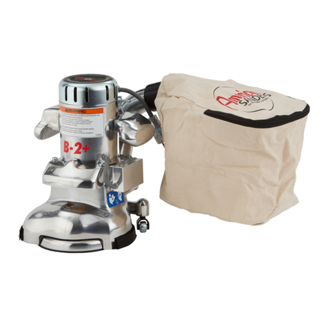
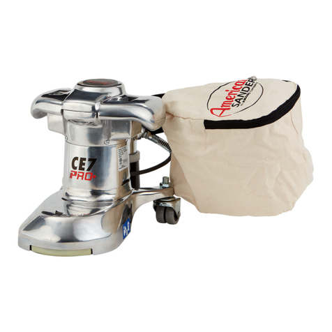
Clarke B2 7" Spinner Edge 07072A User manual

Electronic Service
Manuals
This electronic document is provided as a service to our customers.
Wedonotcreatethecontentsoftheinformationcontainedinthisdocu-
ment. Shouldyouhavedetailedquestionspertainingtotheinformation
contained in this document, you may contact Michco, or the manufac-
turer which provided the original information in this electronic deliver-
able. Michco’sonlypartin this electronic deliverable was the electronic
assemblyprocess. Byprovidingthismanualonlinewearenotguaran-
teeing parts availability.
You may contact Michco through the following methods:
Phone (517) 484-9312 or (800) 331-3339
2011 N. High St. -- Lansing, Michigan -- 48906
Fax: (517) 484-9836
Email: [email protected]
Web site: www.Michco.Com
Parts Web site: www.FloorMachineParts.Com
Order Parts on Line at:
www.FloorMachineParts.Com
Directly to Parts & Service:
By Fax: (517) 702-2041
By Voice: Use numbers above.
Serving the Cleaning Industry Since 1922
Notice: All copyrighted material remains property of original owners, all trademarks are property of respective owners.
ManualsaresubjecttoManufacturer’sreproductionlimitations. Originalsorreproductionswereprovidedbymanufacturers
through a request. We make no warranty as to the correctness of information provided in this document and you assume
allrisk. By placing thesemanualsonlinewe are notdeclaringourcorporation to be anmanufacturerauthorizeddealer or
provider, please check ourwebsiteforauthorizedmanufacturerswerepresent.

Form No. 79001C 1/07 revised 11/10
Operator's Manual / Bedienungshandbuch
Manual del operador / Manuel de l’utilisateur
Manuale per l’operatore /
DE
FR
RU
ES
IT
READ THIS BOOK
LESEN SIE DIESES HANDBUCH
LEA ESTE MANUAL
LISEZ CE MANUEL
IMPORTANTE
EN
B2B2
B2B2
B2
7" Spinner Edger7" Spinner Edger
7" Spinner Edger
English (2-13)
Deutsch (14-25)
Español (26-37)
Français (38-49)
Italiano (50-61)
(62-72)

EN
ENGLISH
-2- FORM NO. 79001C Clarke®American Sanders Operator's Manual (EN) - B2
Operator Safety Instructions.....................................................................3
Machine Specifications .............................................................................5
Machine Set-Up........................................................................................... 6
Sanding Cuts and Sandpaper............................................................... 8
Operating Instructions ................................................................................9
Maintenance.............................................................................................. 1 0
Section II Parts and Service Manual
AssemblyDrawing #1............................................................................. 7 4
Assembly Parts List #1 ........................................................................... 7 5
Assembly Drawing #2............................................................................. 7 6
Assembly Parts List #2 ........................................................................... 7 7
Wiring Diagram ......................................................................................... 7 8
Contents of this Book
READ THIS BOOK
This book has important information for the use and safe operation of this machine. Failure to read
this book prior to operating or attempting any service or maintenance procedure to your Clarke
AmericanSandersmachinecouldresultininjurytoyouortootherpersonnel;damagetothemachine
or to other property could occur as well. You must have training in the operation of this machine
beforeusingit. Ifoperator(s)cannotreadEnglish,havethismanualexplainedfullybeforeattempting
to operate this machine.
All directions given in this book are as seen from the operator’s position at the rear of the machine.
WARNING!
TheProductssoldwiththisManualcontainormaycontainchemicalsthatareknowntocertaingovernments(suchastheStateof
California,asidentifiedinitsProposition65RegulatoryWarningLaw)tocausecancer,birthdefectsorotherreproductiveharm. In
certainlocations(includingtheStateofCalifornia)purchasersoftheseProductsthatplacetheminserviceatanemploymentjobsiteora
publiclyaccessiblespacearerequiredbyregulationtomakecertainnotices,warningsordisclosuresregardingthechemicalsthatareor
maybecontainedintheProductsatoraboutsuchworksites. Itisthepurchaser’sresponsibilitytoknowthecontentof,andtocomply
with,anylawsandregulationsrelatingtotheuseoftheseProductsinsuchenvironments. TheManufacturerdisclaimsanyresponsibility
toadvisepurchasersofanyspecificrequirementsthatmaybeapplicabletotheuseoftheProductsinsuchenvironments.
revised 5/10

EN
ENGLISH
Clarke®American Sanders Operator's Manual (EN) - B2 FORM NO. 79001C - 3 -
DANGER means: Severe bodily injury or death can occur to you or other personnel if the DAN-
GER statements found on this machine or in this Operator's Manual are
ignored or are not adhered to. Read and observe all DANGERstatements
found in this Operator's Manual and on your machine.
WARNING means: Injury can occur to you or to other personnel if the WARNING statements
found on your machine or in this Operator's Manual are ignored or are not
adhered to. Read and observe all WARNING statements found in this
Operator's Manual and on your machine.
CAUTION means: Damage can occur to the machine or to other property if the CAUTION state-
ments found on your machine or in this Operator's Manual are ignored or are
not adhered to. Read and observe all CAUTION statements found in this
Operator's Manual and on your machine.
DANGER: Failure to read the Operator's Manual before operating or servicing this sanding equipment
could result in injury to the operator or to bystanders and could cause damage to the
equipment. Read and observe all safety statements found in this manual and on the
sanding equipment. Make sure all labels, decals, warnings, cautions and instructions are
fastened to the equipment. Replace any that are damaged or missing. You must have
training in the operation of this equipment before using it. If the operator is unable to
read this manual, have it explained fully before they attempt to use this equip-
ment.
DANGER: Sanding/finishing wood floors can create an environment that can be explosive. The
following safety procedures must be adhered to:
• Cigarette lighters, pilot lights and any other source of ignition can create an explosion
when active during a sanding session. All sources of ignition should be extinguished or
removed entirely if possible from the work area.
• Work areas that are poorly ventilated can create an explosive environment when certain
combustible materials are in the atmosphere, i.e., solvents, thinners, alcohol, fuels,
certain finishes, wood dust and other combustible materials. Floor sanding equipment
can cause flammable material and vapors to burn. Read the manufacturer's label on all
chemicals used to determine combustibility. Keep the work area well ventilated.
• Spontaneous combustion or an explosion can occur when working with sanding dust.
The sanding dust can self-ignite and cause injury or damage. Sanding dust should be
disposed of properly. Always empty the sanding dust into a metal container that is
located outside of any building(s).
• Remove the contents of the dust bag when the bag is 1/3 full. Remove the contents of
the dust bag each time you finish using the equipment. Never leave a dust bag unat-
tended with sanding dust in it.
• Do not empty the contents of the dust bag into a fire.
• Hitting a nail while sanding can cause sparks and create an explosion or fire. Always
use a hammer and punch to countersink all nails before sanding floors.
OPERATOR SAFETY INSTRUCTIONS
WARNING AVERTISSEMENT ADVERTENCIA

EN
ENGLISH
-4- FORM NO. 79001C Clarke®American Sanders Operator's Manual (EN) - B2
DANGER: Operating partially assembled sanding equipment could result in injury to the operator or
bystander and could cause damage to the equipment or to other property.
• Do not operate this equipment unless it it fully assembled and all guards, doors and
covers are secured.
• Keep all fasteners tight.
• Keep all adjustments within manufacturers specifications.
DANGER: Moving parts on this sanding equipment can cause injury to the operator or bystanders.
• Keep hands, feet and loose clothing away from all moving parts.
• Do not change or adjust the abrasive while the sanding equipment is running.
• Do not service the sanding equipment while it is running.
DANGER: This sanding equipment requires a supply of electricity. Improper use could result in electrical
shock or fire.
• Connect only to an electrical source matching what is shown on the equipment name-
plate.
• Do not use this sanding equipment on an ungrounded electrical circuit. Consult an
electrician if you suspect the circuit is not properly grounded.
• Do not use this sanding equipment with a damaged electrical cord. Inspect before each
use.
• Avoid striking the elelctrical cord with the abrasive. Always lift the electrical cord over
the sanding equipment.
• Do not use the electrical cord to move the sanding equipment.
• Disconnect the electrical source before servicing this equipment.
WARNING: Injury to the operator or bystander can occur if protective gear is not worn while sanding.
Always use eye, ear, and respiratory protection while performing any sanding operation.
WARNING: Bodily injury could occur if power is applied to the equipment with the power switch already
in the "ON" position. Always check to assure that the power switch is in the "OFF" position
before connecting power supply.
CAUTION: Maintenance and repairs performed by unauthorized personnel could result in damage or
injury. Maintenance and repairs performed by unauthorized personnel will void your warranty.
Servicing of this unit must always be referred to an authorized Clarke American Sanders
distributor.
CAUTION: Use of this equipment to move other objects or to climb on could result in injury or damage.
Do not use this equipment as a step or furniture. Do not ride on this equipment.
CAUTION: Damage could occur to the equipment if not properly kept in a dry building for storage. Store
the equipment in a dry building.
CAUTION: Serious damage to the floor can occur if the sanding equipment is left running in one spot while
the sanding disc is in contact with the floor. To avoid damage to the floor, do not dwell while
lowering or raising the sanding disc. Always sand with a constant motion.

EN
ENGLISH
Clarke®American Sanders Operator's Manual (EN) - B2 FORM NO. 79001C - 5 -
IntroductionandMachineSpecifications
The B-2 is specifically designed for finishing floor edges, stairs, and other hard-to-reach surfaces. The handle
location and low center of gravity make the B-2 easy to operate.
The excellent cutting power comes from a powerful universal type motor. A motor that delivers maximum
performance without slowing down or overheating. Its exclusive two speed control when switched to hi-speed
produces 3200 rpm for fast, rough sanding. At low speed, the B-2 operates at 2800 rpm for fine, finish sanding.
A non marking disc guard protects the rubber pad, permitting the edger to work right up to the baseboard or wall.
Specifications
Voltage/Frequency 110V-120V /50-60 Hz 220V-240 /50-60 Hz
Amperage 13.0 6.5
Motor 1450W (1 HP) 1450W (1 HP)
Sound Level 91dB (A) 91dB (A)
Vibration 5.7 m/s2 rms 5.7 m/s2 rms
Abrasive Size 178mm x 22 mm Dia. (7" x 7/8" Dia.) 178mm x 22 mm Dia. (7" x 7/8" Dia.)
Disc Rate High 3200 RPM 3200 RPM
Disc Rate Low 2800 RPM 2800 RPM
Gears Hardened steel alloy pinion Hardened steel alloy pinion
and drive gear. and drive gear.
Bearings Sealed ball bearings, Sealed ball bearings,
lifetime lubricated. lifetime lubricated.
DustCollector Powerful vacuum fan, full Powerful vacuum fan, full
aluminum skirt aluminum skirt
Power Cord 12m H07RN F3G 1.5mm
212m H07RN F3G 1.5mm
2
Dimensions 356 x 260 x 343mm (14 x 10½ x 13½) 356 x 260 x 343mm (14 x 10½ x 13½)
Weight 14.5 kg (32 lbs) 14.5 kg (32 lbs)
Shipping Weight 21 kg (46 lbs) 21 kg (46 lbs)
Powerful Universal Motor
High Low Switch
Powerful Vacuum Fan for effecient dust pickup
Non-Marking Roller Guard
Non-Marking Swivel Type
Casters
Balanced Sanding Disc
for perfectly matched job
Aluminum Alloy Casting
Comfortable Operating
Handles
Hardened Steel Alloy
Pinon and Drive Gear
revised 5/10

EN
ENGLISH
-6- FORM NO. 79001C Clarke®American Sanders Operator's Manual (EN) - B2
MachineSet-Up
This sanding machine is designed to be operated with a
remote vacuum dust collection system or with the included
dust bag.
Preparing Remote Vacuum Dust Collection Systems
To prepare the machine for remote vacuum dust collection
systems that have a 2" hose end, follow this procedure:
1. Install 2" hose end (figure 1, A) directly over the
exhaust tube (figure 1, B).
2. The exhaust tube can be rotated for optimum conve-
nience.
To prepare the machine for remote vacuum dust collection
systems that have a 1 ½" hose end, follow this procedure:
1. Install the 2" x 1½" hose end adaptor (Part No.
30563A) (figure 1, C) over the exhaust tube (figure 1,
B).
2. Insert 1 ½" hose end (figure 1, D) into the adaptor
(figure 1, C).
NOTE: Start the remote vacuum collection system
before operation.
Preparing to use the included dust bag
To prepare the machine for use with the included dust bag
(Part No. 53544B), follow this procedure:
1. Install the dust bag by pressing the end onto the
exhaust tube until the ring locks into the groove (figure
2). This is best done by pressing on the back of the
bag opening with the palm of your hand.
2. The exhaust tube can be rotated for optimum conve-
nience.
3. To remove the dust bag from the exhaust tube, pry up
the end of the bag opening to partially release the
internal rib from the groove, then pull.
4. To empty the dust bag, unzip the disposal flap and
force contents out by inverting the bag.
NOTE: For best results, empty frequently. Follow all
warnings posted in this manual and on the dust bag.
Install the dust bag by
pressing the end onto the
exhaust tube until the ring
locks into the groove.
A
2" Hose from
vacuum system
(not included)
1.5" Hose from
vacuum system
(not included)
D
B
C
Exhaust Tube
(30563A) 2" Tube x 1.5" hose adaptor
Figure 1
Figure 2

EN
ENGLISH
Clarke®American Sanders Operator's Manual (EN) - B2 FORM NO. 79001C - 7 -
Figure 3
Figure 4
Machine Set-Up
How to Install the Sandpaper
1. To install or replace abrasive, turn the machine
upside down and let it rest on the motor cover.
With the wrench supplied, remove the screw and
abrasive retainer. Hold pad to prevent it from
rotating and turn wrench. See figure 3
2. Center abrasive on pad and install the abrasive
retainer and screw. Tighten screw. See figure 4.
3. Return machine to upright position.
WARNING: Serious injury could occur when at-
tempting to replace abrasive while
machine is connected to power supply.
Always disconnect power before
installing abrasive.
CAUTION: Gearbox damage could result from
machine resting upside down for
extended periods of time. Lubricant
may drain from gearbox. Always return
machine to upright position after
installing abrasive.

EN
ENGLISH
-8- FORM NO. 79001C Clarke®American Sanders Operator's Manual (EN) - B2
Sanding Cuts and SandpaperSanding Cuts and Sandpaper
Sanding Cuts and Sandpaper
InitialCut
The purpose of the initial cut is to remove old finish and gross imperfections on the floor surface. A coarse
abrasive should be used. If the surface is severely damaged by deep scratches, pre-existing dwell marks,
uneven planks, etc., it may be necessary to sand across or diagonally to the grain to restore evenness to the
surface. If these conditions are not present, the initial cut should be done in the direction of the grain.
If glazing, loading, or burning takes place immediately into an initial cut, select a coarser abrasive. If this
should occur during an initial cut, the abrasive has dulled and must be replaced.
Final Cuts
The purpose of a finishing cut is to remove the scratches produced during the initial cut. Use a fine (60 - 80
grit) grain abrasive.
If the surface remains rough after a finishing cut, it may be necessary to use an even finer grain of abrasive (80
- 100 grit). Care should be taken in selecting the grit size of the abrasive. A very fine grain will close the
pores on a wood floor making admission of a stain difficult.
If glazing or burning should occur immediately into a finishing cut, increase pace. If it should occur during a
finishing cut, the abrasive has dulled and must be replaced.
12 grit For removing gross imperfections and restore evenness
16 grit to old flooring. To remove build-up of paints and varnishes.
20 grit
30 grit For first sanding of new flooring (maple, oak). For removing
36 grit minor imperfections and finishes from old flooring.
40 grit For initial cut on new flooring (oak, walnut). For removing
minor imperfections and finishes from old flooring.
50 grit For first sanding of new flooring (cedar, pine, fir)
For clean-up of 16 grit.
60 grit For clean-up from initial cut 36 grit.
80 grit For final sanding of certain hardwoods. For clean-up
of initial cuts (50 grit).
100 grit For final sanding of certain hardwoods and conifers where
a smooth surface is desired.
120 grit For finishing cut on certain conifers.
150 grit For finishing cut on certain conifers where a smooth
surface is desired.
Grain Use Standard Grade
Part #/Qty
945300/50
945301/50
945302/50
945594/200
945595/200
945596/200
945598/300
945599/300
945305/100
945600/300
945307/100
945308/100
945601/300
945602/300
945309/100 945603/300
945310/100 945604/300
945605/500
945606/300
Professional Grade
Part #/Qty

EN
ENGLISH
Clarke®American Sanders Operator's Manual (EN) - B2 FORM NO. 79001C - 9 -
OperatingInstructions
DANGER: Failure to disconnect the supply cable from
machine whenever servicing, replacing
abrasive, or emptying the dust bag could
result in electrocution or severe injury.
Never leave machine unattended while the
supply cable is connected.
DANGER: Never leave dust bag unattended with
sanding dust in it. Sanding dust can
spontaneously ignite and cause a fire or
explosion. Empty dust bag into a metal
container, clear of any combustibles. Do
not empty content into a fire. Do not
overfill dust bag.
To operate the machine, follow this procedure:
1. Set any exposed nails with a hammer and punch to
avoid encounter with sanding pad.
2. Connect the machine to an appropriately grounded and
fused circuit (power supply).
3. Tilt the machine back so that the sanding pad does not
contact the floor. See figure 5.1. Select cutting speed.
Use high speed for fast stock removal. Use low speed
for finish cuts and custom work. See
figure 6.
4. Grasp both handles and press the control switch to the
start position. Once started, allow the switch to return
to the run (ON) position. See figure 5.2.
5. Gradually lower sanding pad to the floor. Make sure
the machine is in motion while the sanding pad is
engaged with the floor. Broad circular motions can be
used as you sand along the length of the floor or you
may use a combination of forward and sideway
motions. In time you will develop your own technique
to optimize coverage and dust control. It is advisable
to not add effort to the pad as this may lead to
"nosing" or "tipping" which produces grooves or lines
on the floor.
6. When replacing abrasive; emptying the contents of the
dust bag; or the sanding operation is completed, return
the machine to the reclined position and flip the control
switch to the off (O) position. Disconnect the machine
from the power supply.
7. Empty dust bag whenever it becomes 1/3 full.
Figure 5
Figure 6

EN
ENGLISH
-10- FORM NO. 79001C Clarke®American Sanders Operator's Manual (EN) - B2
MAINTENANCE
CAUTION: Maintenance and repairs performed by
unauthorized personnel could result in
damage or injury. Maintenance and
repairs performed by unauthorized
personnel will void your warranty.
Servicing of these units must always be
referred to an authorized Clarke Ameri-
can Sanders distributor.
TheDustControlSystem
Remove the dust from the bag when the bag is
1/3
full or when the efficiency of the dust control system
decreases.
If the exhaust pipe gets an obstruction, follow this
procedure:
1. Remove the four screws that hold the exhaust pipe
to the housing. See figure 7.
2. Remove the obstruction from the exhaust pipe.
3. Install the exhaust pipe.
How to Adjust the Angle Of The Sandpaper Disc To
The Floor
The adjustment of the machine is correct when the front
part of the sandpaper disc makes contact with the floor.
To change the adjustment of the machine, follow
thisprocedure:
1. Using the special wrench, loosen the lock nut on
each caster. See (1) figure 8.1.
2. Loosen the jam nut. See (2) figure 8.2.
3. Raise or lower the casters as needed.
4. Tighten the jam nut on each caster.
5. Tighten the lock nut on each caster.
The Ventilation Plug
1. To clean the ventilation opening in the center of the
plug, remove the plug from the machine. With the
plug removed, also inspect the grease in the
gearbox. See figure 9.
Figure 7
Figure 9
Figure 8

EN
ENGLISH
Clarke®American Sanders Operator's Manual (EN) - B2 FORM NO. 79001C - 11 -
Figure 10
Figure 11
Figure 12
MAINTENANCE
Lubrication
The machine is completely lubricated. The bearings and
gears in the gear unit have enough lubricant for approximately
six months of normal operation. All other bearings are sealed
and have enough lubricant for the life of the machine. No
lubricant is needed for the rotating disc guard.
How To Change The Lubricant In The Gearbox
To change the lubricant in the gearbox, follow this procedure:
1. Put the machine upside down on a bench.
2. Align one of the two holes in the rubber pad with one of
the three holes in the rotating disc guard.
3. Align both holes with one of the three screws in the
gear housing cover. Remove the screw from the gear
housing cover. See figure 10.
4. Align the holes with each of the other two screws, then
remove screws.
CAUTION:Make sure no dust enters the gear
box. Damage could occur to the gear
box.
5. Remove the cover from the gear housing.
6. Remove the old lubricant from the gearbox.
7. Add ten ounces of Clarke American Sanders lubricant
to the gearbox.
CAUTION:To prevent damage to the motor,
do not add more than ten ounces
of lubricant to the gearbox.
8. Using the three screws removed above, install the cover
on the gear housing.
9. Start the machine and let it run for 15 minutes. A small
amount of excess lubricant should flow out the vent
hole. If none appears it may be necessary to add
additional lubricant.
10. Wipe off excess lubricant and clear vent hole.
How To Check The Carbon Brushes
Depending on use, a set of brushes can be expected to last
250 hours and should be inspected sometime prior to that
time.
To check the brushes, follow this procedure:
1. Remove the motor cover. See figure 11.
2. Inspect the carbon brushes. Replace both brushes if
either brush has worn to 3/8" in length, or is worn to the
wear indicator. See figure 12.
3. To replace the brushes, disconnect the field wire (A)
from the brush holder (B). Then remove the two screws
and washers (C) securing the holder to the motor
housing. See figure 13.
Lubricants
Qty Part No.
1 Qt. 16610A
1 Gal. 16611A
Figure 13
A
A
B
B
C
C
C
C

EN
ENGLISH
-12- FORM NO. 79001C Clarke®American Sanders Operator's Manual (EN) - B2
MAINTENANCE
How To Check The Carbon Brushes (cont)
4. Gently pry the holder down from the motor housing.
5. Rotate holder from beneath the motor housing and lift
out.
6. Disconnect the brush shunt wire from the holder.
For convenience, cut the terminal from the shunt wire
and remove brush.
7. To put in a new carbon brush, negotiate the terminal
on the shunt wire by the spring and brush holder
guide. Take care not to damage the spring. See
figure 14.
8. Depress the brush into the guide and connec the
shunt wire to the holder.
9. Depress the brush and insert the holder into the
motor housing.
10. Rotate holder beneath motor housing. Relax brush
against commutator.
11. Align posts on holder with holes in housing.
12. Gently pry the holder into the housing.
13. Reattach screws and washers.
14. Start up the machine, if sparking between either
brush and the commutator occurs, use a brush
seating stone on the commutator to promote full
engagement between the brushes and commutator.
15. Install the motor cover.
Figure 14

EN
ENGLISH
Clarke®American Sanders Operator's Manual (EN) - B2 FORM NO. 79001C - 13 -
NOTES

-14- FORM NO. 79001C Clarke®American Sanders Bedienungshandbuch (DE) - B2
DE
DEUTSCH
LESEN SIE DIESES HANDBUCH
Dieses Handbuch enthält wichtige Informationen für den Gebrauch und den sicheren Betrieb dieser
Maschine. Versäumen Sie es, dieses Handbuch vor der Inbetriebnahme oder vor der Ausführung von
Service- oder Wartungsarbeiten an Ihrer Clarke American Sanders-Maschine zu lesen, kann dies zu
Schäden Ihrer Person oder anderen Personals führen. Ebenso könnten Schäden an der Maschine
oder andere Sachschäden auftreten. Bevor Sie diese Maschine bedienen, müssen Sie sich mit Ihrer
Bedienung vertraut gemacht haben. Wenn Sie kein Englisch verstehen, lassen Sie sich dieses
Handbuch vor Bedienung dieser Maschine vollständig erklären.
Alle in diesem Handbuch angegebenen Richtungen beziehen sich auf die Position des Bedieners
hinter der Maschine.
Inhaltsverzeichnis
Sicherheitsanweisungen für den Benutzer ...................................... 15
Einführung und Maschinendaten ........................................................ 17
Maschinenaufbau .................................................................................... 18
Schliffe und Schleifpapier ................................................................... 20
Bedienungsanweisung .......................................................................... 21
Routinemäßige Wartungsarbeiten...................................................... 22
Teil II Teile- und Servicehandbuch
Montagezeichnung #1...............................................................74
Montageteileliste #1 ................................................................................ 75
Montagezeichnung #2 ............................................................................ 76
Montageteileliste #2 ................................................................................ 77
Schaltplan ...................................................................................................... 78
revised 11/10

Clarke®American Sanders Bedienungshandbuch (DE) - B2 FORM NO. 79001C -15-
DE
DEUTSCH
GEFAHR bedeutet: Schwere Körperverletzungen mit möglicher Todesfolge können für Sie oder
Personal eintreten, wenn die durch GEFAHRgekennzeichneten Anweisungen
an dieser Maschine oder in diesem Bedienungshandbuch ignoriert oder nicht
befolgt werden. Lesen und befolgen Sie alle durch GEFAHRgekennzeichneten
Anweisungen an dieser Maschine oder in diesem Bedienungshandbuch.
WARNUNG bedeutet: Verletzungen mit möglicher Todesfolge können für Sie oder Personal eintreten,
wenn die durch WARNUNGgekennzeichneten Anweisungen an dieser
Maschine oder in diesem Bedienungshandbuch ignoriert oder nicht befolgt
werden. Lesen und befolgen Sie alle durch WARNUNGgekennzeichneten
Anweisungen an dieser Maschine oder in diesem Bedienungshandbuch.
VORSICHT bedeutet: Schäden können an der Maschine oder anderem Eigentum eintreten, wenn die
durch VORSICHTgekennzeichneten Anweisungen an dieser Maschine oder in
diesem Bedienungshandbuch ignoriert oder nicht befolgt werden. Lesen und
befolgen Sie alle durch VORSICHTgekennzeichneten Anweisungen an dieser
Maschine oder in diesem Bedienungshandbuch.
GEFAHR: Ein Versäumnis, dieses Buch vor Inbetriebnahme der Maschine oder Durchführung von
Instandhaltungs- oder Wartungsarbeiten an dieser Schleifmaschine zu lesen, kann
Bedienungspersonal oder unbeteiligte Personen Verletzungsgefahr aussetzen oder
Maschinenschäden verursachen. Lesen und befolgen Sie alle Sicherheitsanweisungen in
diesem Handbuch und an der Schleifmaschine. Sorgen Sie dafür, dass alle Etiketten,
Schilder, Warnungen, Vorsichtshinweise und Anweisungen an der Maschine angebracht
sind. Ersetzen Sie alle beschädigten oder fehlenden Hinweise. Sie müssen in der
Benutzung dieser Maschine unterwiesen sein, bevor Sie sie in Betrieb nehmen. Ist das
Bedienungspersonal nicht in der Lage, dieses Handbuch zu lesen, sorgen Sie
dafür, dass ihm dieses Handbuch vollständig erklärt wird, bevor diese Maschine in
Betrieb genommen wird.
GEFAHR: Durch das Abschleifen bzw. Fertigstellen von Holzböden kann eine Umgebung entstehen,
die explosionsgefährlich sein kann. Die folgenden Sicherheitsverfahren sind zu befolgen:
• Feuerzeuge, Anzünder und andere Zündquellen können eine Explosion verursachen,
wenn sie während der Schleifarbeiten aktiviert werden. Alle Zündquellen müssen
gelöscht oder, soweit möglich, vollkommen aus dem Arbeitsbereich entfernt werden.
• Schlecht entlüftete Arbeitsbereiche können eine explosionsgefährliche Umgebung
schaffen, wenn die Atmosphäre bestimmtes Brennmaterial wie zum Beispiel
Lösungsmittel, Verdünner, Alkohol, Brennstoffe, bestimmte Finishs, Holzstaub und
ähnliche Stoffe enthält. Bodenschleifgeräte können entzündbares Material und
brennbare Dämpfe entstehen lassen. Lesen Sie auf allen Chemikalien das Etikett des
Herstellers, um den Entzündbarkeitsgrad festzustellen. Sorgen Sie dafür, dass der
Arbeitbereich gut entlüftet wird.
• Bei Arbeiten mit Schleifstaub kann eine Selbstentzündung oder Explosion ausgelöst
werden. Der Schleifstaub kann sich selbst entzünden und Verletzungen oder Schäden
verursachen. Schleifstaub muss vorschriftsmäßig entsorgt werden. Leeren Sie den
Schleifstaub immer in einen Metallbehälter, der außerhalb von Gebäuden aufgestellt ist.
• Entleeren Sie den Inhalt des Staubsacks, wenn dieser zu einem Drittel gefüllt ist.
Entleeren Sie immer den Inhalt des Staubsacks, wenn die Benutzung der Maschine
beendet ist. Lassen Sie niemals einen mit Schleifstaub gefüllten Staubsack
unbeaufsichtigt zurück.
• Entleeren Sie den Inhalt des Staubsacks niemals in eine offene Flamme.
• Beim Einschlagen von Nägeln während der Schleifarbeiten können Funken entstehen,
die eine Explosion oder einen Brand verursachen können. Benutzen Sie immer einen
Hammer und Einsenker, um alle Nägel einzusenken, bevor der Boden geschliffen wird.
SICHERHEITSHINWEISE FÜR BEDIENER

-16- FORM NO. 79001C Clarke®American Sanders Bedienungshandbuch (DE) - B2
DE
DEUTSCH
GEFAHR: Die Inbetriebnahme einer nur teilweise zusammengebauten Schleifmaschine kann
Bedienungspersonal oder unbeteiligte Personen Verletzungsgefahr aussetzen und Schäden
an der Maschine oder anderem Eigentum verursachen.
• Nehmen Sie diese Maschine nur dann in Gebrauch, wenn sie vollständig
zusammengebaut ist und alle Schutzvorrichtungen, Türen und Abdeckungen sicher
angebracht sind.
• Sorgen Sie dafür, dass alle Befestigungsvorrichtungen fest angezogen sind.
• Achten Sie darauf, dass alle Justierungen den Vorgaben des Herstellers entsprechen.
GEFAHR: Die beweglichen Teile dieser Schleifmaschine können Bedienungspersonal oder unbeteiligte
Personen Verletzungsgefahr aussetzen.
• Halten Sie Hände, Füße und lockere Kleidungsstücke von allen beweglichen Teilen fern.
• Ersetzen oder justieren Sie das Schleifmaterial nicht, während die Schleifmaschine läuft.
• Führen Sie keine Wartungsarbeiten durch, während die Schleifmaschine läuft.
GEFAHR: Diese Schleifmaschine erfordert eine Stromversorgung. Eine unsachgemäße Benutzung
kann einen Stromschlag oder Brand verursachen.
• Schließen Sie die Maschine nur an eine Stromversorgungsquelle an, die den Angaben
auf dem Maschinenschild entspricht.
• Schließen Sie diese Schleifmaschine nicht an einen ungeerdeten Stromkreis an.
Vermuten Sie, dass der Stromkreis nicht richtig geerdet ist, ziehen Sie bitte einen
Elektriker hinzu.
• Benutzen Sie diese Schleifmaschine nicht, wenn das Stromkabel beschädigt ist.
Untersuchen Sie die Maschine vor jeder Inbetriebnahme.
• Vermeiden Sie, dass das Stromkabel mit dem Schleifmaterial in Berührung kommt.
Heben Sie das Stromkabel immer über die Schleifmaschine.
• Benutzen Sie nicht das Stromkabel, um die Schleifmaschine zu bewegen.
• Schalten Sie die Stromversorgung aus, bevor Sie Wartungsarbeiten an dieser Maschine
durchführen.
WARNUNG: Bedienungspersonal oder unbeteiligte Personen sind Verletzungsgefahr ausgesetzt, wenn
beim Schleifen keine Schutzausrüstung getragen wird. Benutzen Sie während des Schleifens
immer Schutzbrille, Ohrenschutz und Atemschutz.
WARNUNG: Bediener können Körperverletzungen erleiden, wenn die Maschine unter Strom gesetzt wird,
wenn der Stromschalter bereits auf “EIN” steht. Vergewissern Sie sich immer, dass der
Stromschalter auf “AUS” steht, bevor Sie die Maschine an die Stromversorgung anschließen.
VORSICHT: Von unbefugtem Personal durchgeführte Wartungs- und Reparaturarbeiten können Schäden
oder Verletzungen zur Folge haben. Von unbefugtem Personal durchgeführte Wartungs- und
Reparaturarbeiten hebt Ihre Garantie auf. Instandhaltungsarbeiten an dieser Maschine sind
immer an einen zugelassenen Händler für Clarke American Sanders weiterzuleiten.
VORSICHT: Die Benutzung dieser Maschine zur Bewegung anderer Gegenstände oder das Klettern auf
diese Maschine kann Schäden oder Verletzungen zur Folge haben. Benutzen Sie diese
Maschine nicht als Stufe oder Möbelstück. Benutzen Sie diese Maschine nicht als
Aufsitzgerät.
VORSICHT: Diese Maschine kann Schaden nehmen, wenn sie nicht vorschriftsmäßig in einem trockenen
Gebäude aufbewahrt wird. Bewahren Sie die Maschine in einem trockenen Gebäude auf.
VORSICHT: Eine schwere Beschädigung des Bodens kann eintreten, wenn die Schleifmaschine auf der
Stelle läuft und die Schleifscheibe mit dem Boden in Berührung ist. Um Bodenschäden zu
vermeiden, verweilen Sie nicht an einer Stelle, wenn Sie die Schleifscheibe senken oder
anheben. Schleifen Sie immer mit konstanten Bewegungen.

Clarke®American Sanders Bedienungshandbuch (DE) - B2 FORM NO. 79001C -17-
DE
DEUTSCH
Einführung und Daten der Maschine
Die B-2 ist speziell zum Schleifen von Bodenkanten, Treppen und anderen schwer erreichbaren Oberflächen
geeignet. Der Sitz des Griffes und der niedrige Schwerpunkt machen die American B-2 leicht
zu bedienen.
Die exzellente Schleifleistung wird durch den leistungsstarken Universaltypmotor erzielt. Ein Motor, der höchste
Leistung ohne Verlangsamung oder Ueberhitzen bietet. Seine exklusive Geschwindigkeitskontrolle mit zwei
Stufen erreicht auf hoher Geschwindigkeitsstufe 3200 Umdrehungen pro Minute für schnelles, grobes Schleifen.
Bei niedriger Geschwindigkeit arbeitet der B-2 bei 2800 Umdrehungen pro Minute für feines Endschleifen. Ein
spurenloser Schleifscheibenschutz schützt die Gummifläche und erlaubt dem Hobel
Arbeiten bis dicht an Fußleiste oder Wand.
Daten
Spannung/Frequenz 110V-120V/ 50-60 Hz 220V-240V/50-60 Hz
Stromstärke 13.0 6.5
Motor 1 PS 1 PS
Schallemission (Lpm) 91 dB (A) 91 dB (A)
Schwingung 5.7 m/s2rms 5.7 m/s2rms
Schleifmaterialgröße 17,78 x 2,22 cm Durchmesser 17,78 x 2,22 cm Durchmesser
Schleifscheibengeschwindigkeit hoch 3200 Umdrehungen/Minute 3200 Umdrehungen/Minute
Schleifscheibengeschwindigkeit 2800 Umdrehungen/Minute 2800 Umdrehungen/Minute
niedrig
Zahnräder Ritzel und Antriebszahnrad aus Ritzel und Antriebszahnrad aus
gehärteter Stahllegierung. gehärteter Stahllegierung.
Lager Versiegelte Kugellager, Versiegelte Kugellager,
auf Lebensdauer geschmiert. auf Lebensdauer geschmiert.
Schalter Positiv-Prinzip, An-Aus-Hebel. Positiv-Prinzip, An-Aus-Hebel.
Staubsammler Leistungsstarker Leistungsstarker
Vakuumventilator, Vakuumventilator,
rundum Aluminiumeinfassung. rundum Aluminiumeinfassung.
Stromkabel 12m HO7RN F3G 1,5mm212m HO7RN F3G 1,5mm2
Abmessungen 35.5 cm x 26.7 cm x 34.3 cm 35.5 cm x 26.7 cm x 34.3 cm
Gewicht 14,5 kg 14,5 kg
Versandgewicht 20,9 kg 20,9 kg
Leistungsstarker Universalmotor
Auf/Ab-Schalter
Leistungsstarker Vakuumventilator für effektive
Staubaufnahme
Spurenfreier Rollenschutz
Spurenfreie schwenkbare
Laufrollen
Ausbalancierte
Schleifscheibe für perfekte
Ausführungen
Fuß aus Aluminiumguß
Bequeme Bedienungsgriffe
Ritzel und Antriebszahnrad
aus gehärtetem Stahl
revised 5/10

-18- FORM NO. 79001C Clarke®American Sanders Bedienungshandbuch (DE) - B2
DE
DEUTSCH
1,50"
SCHLAUCHSTÜCK
FÜR
STAUBSAUGER
(NICHT IM
LIEFERUMFANG
ENTHALTEN)
B
C
LUFTSCHLAUCH 30563A 2"-SCHLAUCHSTÜCK X
1,50"-SCHLAUCH-ADAPTER
Abbildung 2
A
2"-SCHLAUCHSTÜCK
FÜR STAUBSAUGER
(NICHT IM
LIEFERUMFANG
ENTHALTEN)
D
Den Staubbeutel auf das
Abluftrohr schieben, bis
der Ring in der Rille
einrastet.
Die vorliegende Schleifmaschine ist für den Betrieb
zusammen mit einem externen Staubsammelsystem oder
dem beiliegenden Staubbeutel vorgesehen.
Vorbereitung eines externen Staubabsaug- und
Sammelsystems
Die Maschine wird für externe Staubabsaug- und
Sammelsysteme mit einem Anschluß für 2"-Schläuche
folgendermaßen vorbereitet:
1. Das 2"-Schlauchstück (Abbildung 1 A) direkt über das
Abluftrohr ziehen (Abbildung 1 B).
2. Das Abluftrohr kann zur leichteren Handhabung gedreht
werden.
Die Maschine wird für externe Staubabsaug- und
Sammelsysteme mit einem Anschluß für 1½”-Schläuche
folgendermaßen vorbereitet:
1. Den 2" x 1½” Schlauch-Adapter (Teile-Nr. 30563A)
(Abbildung 1 C) über das Abluftrohr ziehen (Abbildung 1
B).
2. Das 1½”-Schlauchstück (Abbildung 1 D) in den Adapter
stecken (Abbildung 1 C).
HINWEIS: Das externe Staubabsaug- und Sammelsystem
vor Inbetriebnahme der Maschine einschalten.
Vorbereitung für die Verwendung des mitgelieferten
Staubbeutels
Die Maschine wird für die Verwendung mit dem
mitgelieferten Staubbeutel (Teile-Nr. 53544B),
folgendermaßen vorbereitet:
1. Den Staubbeutel auf das Abluftrohr schieben, bis der
Ring in der Rille einrastet. (Abbildung 2). Hierzu drücken
Sie am besten mit der Handfläche gegen die Rückseite
des Beutels.
2. Das Abluftrohr kann zur leichteren Handhabung gedreht
werden.
3. Zum Abnehmen des Staubbeutels vom Abluftrohr die
Beutelöffnung aufspreizen, um den Innenring etwas aus
der Rille herauszulösen und den Beutel dann abziehen.
4. Zum Leeren des Staubbeutels die Entleerungsklappe
öffnen und den Inhalt durch Umstülpen des Beutels
entleeren.
HINWEIS: Für beste Ergebnisse den Beutel öfters entleeren.
Alle Warnhinweise in dieser Bedienungsanleitung und auf
dem Staubbeutel beachten.
Maschinenaufbau
Abbildung 1

Clarke®American Sanders Bedienungshandbuch (DE) - B2 FORM NO. 79001C -19-
DE
DEUTSCH
Maschinenaufbau
Um Schleifmaterial zu ersetzen
1. Um Schleifmaterial zu ersetzen, drehen Sie die
Maschine um und stützejn sie auf die
Motorabdeckung. Entfernen Sie die Schraube und den
Schleifmaterialhalter mit dem bereitgestellten
Schlüssel. Halten Sie die Oberfläche fest, damit sie
sich nicht dreht, und drehen Sie den Schlüssel. Siehe
Abbildung 3.
2. Zentrieren Sie das Schleifmaterial auf der Oberfläche
und installieren Sie den Schleifmittelhalter und die
Schraube. Ziehen Sie die Schraube an. Siehe
Abbildung 4.
3. Bringen Sie die Maschine wieder in lhre aufrechte
Position.
WARNUNG: Es kann zu schweren Verletzungen
führen, solten Sie versuchen, das
Schleifmaterial zu wechseln, während
die Maschine an die Stromversorgung
angeschlossen ist. Stecken Sie die
Maschine stets aus, wenn Sie
Schleifmaterial einsetzen.
VORSICHT: Es können Schäden am Getriebe
entstehen, wenn die Maschine für
längere Zeit umgedreht bleibt.
Schmiermittel könnte aus dem Getriebe
auslaufen. Bringen Sie die Maschine
stets wieder in ihre aufrechte Position,
nachdem Sie das Schleifmaterial
gewechselt haben.
Abbildung 3
Abbildung 4
This manual suits for next models
4
Table of contents
Languages:
Other Clarke Edger manuals

Clarke
Clarke American B-2 User manual

Clarke
Clarke Super 7R Installation and operating manual

Clarke
Clarke 07127A User manual

Clarke
Clarke American B-2 User manual

Clarke
Clarke Super 7R User manual

Clarke
Clarke Super E User manual

Clarke
Clarke 07170A User manual

Clarke
Clarke 07097A User manual

Clarke
Clarke American Sanders 07011A User manual

Clarke
Clarke 07127A User manual