Clarke 07127A User manual

Form No. 70896A 1/07 revised 1/14
American
B-2+DC
7" Edger
Operator's Manual / Manual del operador / Manuel de l’utilisateur
ACTIVE MODELS: 07127A (115V), 07096A (230V/25-60HZ)
OBSOLETE MODEL: 07128A (230V/60HZ)
This book has important information for the use and safe operation of this machine. Failure to read
this book prior to operating or attempting any service or maintenance procedure to your Clarke
American Sanders machine could result in injury to you or to other personnel; damage to the machine
or to other property could occur as well. You must have training in the operation of this machine
before using it. If your operator(s) cannot read this manual, have it explained fully before attempting
to operate this machine.
All directions given in this book are as seen from the operator’s position at the rear of the machine.
English (2 - 12)
Español (14 - 24)
Français (26 - 36)
ES
EN
FR
READ THIS BOOK
LEA ESTE MANUAL
LISEZ CE MANUEL

EN
ENGLISH
-2- FORM NO. 70896A Clarke®American Sanders Operator's Manual (EN) - American B2
Contents of this Book
Operator Safety Instructions........................................................ 3
Introduction and Machine Specifications..................................... 5
Machine Set-Up........................................................................... 6
How to Prepare the Machine for Operation................................. 7
Sanding Cuts and Sandpaper .................................................... 8
How to Operate the Machine....................................................... 9
Maintenance................................................................................ 9
SECTION II: Parts Manual
Lower Assy .......................................................................... 38-39
Upper Assy ........................................................................... 40-41
Wiring Diagram.......................................................................... 41
WARNING!
The Products sold with this Manual contain or may contain chemicals that are known to certain governments (such as the State of
California, as identified in its Proposition 65 Regulatory Warning Law) to cause cancer, birth defects or other reproductive harm. In
certain locations (including the State of California) purchasers of these Products that place them in service at an employment job site
or a publicly accessible space are required by regulation to make certain notices, warnings or disclosures regarding the chemicals
that are or may be contained in the Products at or about such work sites. It is the purchaser’s responsibility to know the content of,
and to comply with, any laws and regulations relating to the use of these Products in such environments. The Manufacturer disclaims
any responsibility to advise purchasers of any specific requirements that may be applicable to the use of the Products in such
environments.
revised 3/13

EN
ENGLISH
Clarke®American Sanders Operator's Manual (EN) - American B2 FORM NO. 70896A - 3 -
DANGER means: Severe bodily injury or death can occur to you or other personnel if the
DANGER statements found on this machine or in this Operator's Manual are
ignored or are not adhered to. Read and observe all DANGER statements
found in this Operator's Manual and on your machine.
WARNING means: Injury can occur to you or to other personnel if the WARNING statements
found on your machine or in this Operator's Manual are ignored or are not
adhered to. Read and observe all WARNING statements found in this
Operator's Manual and on your machine.
CAUTION means: Damage can occur to the machine or to other property if the CAUTION state-
ments found on your machine or in this Operator's Manual are ignored or are
not adhered to. Read and observe all CAUTION statements found in this
Operator's Manual and on your machine.
DANGER: Failure to read the Operator's Manual before operating or servicing this sanding equip-
ment could result in injury to the operator or to bystanders and could cause damage to
the equipment. Read and observe all safety statements found in this manual and on the
sanding equipment. Make sure all labels, decals, warnings, cautions and instructions are
fastened to the equipment. Replace any that are damaged or missing. You must have
training in the operation of this equipment before using it. If the operator is unable to
read this manual, have it explained fully before they attempt to use this equipment.
DANGER: Sanding/finishing wood floors can create an environment that can be explosive. The fol-
lowing safety procedures must be adhered to:
• Cigarette lighters, pilot lights and any other source of ignition can create an explosion
when active during a sanding session. All sources of ignition should be extinguished
or removed entirely if possible from the work area.
• Work areas that are poorly ventilated can create an explosive environment when
certain combustible materials are in the atmosphere, i.e., solvents, thinners, alcohol,
fuels, certain finishes, wood dust and other combustible materials. Floor sanding
equipment can cause flammable material and vapors to burn. Read the manufactur-
er's label on all chemicals used to determine combustibility. Keep the work area well
ventilated.
• Spontaneous combustion or an explosion can occur when working with sanding dust.
The sanding dust can self-ignite and cause injury or damage. Sanding dust should
be disposed of properly. Always empty the sanding dust into a metal container that is
located outside of any building(s).
• Remove the contents of the dust bag when the bag is 1/3 full. Remove the contents of
the dust bag each time you finish using the equipment. Never leave a dust bag unat-
tended with sanding dust in it.
• Do not empty the contents of the dust bag into a fire.
• Hitting a nail while sanding can cause sparks and create an explosion or fire. Always
use a hammer and punch to countersink all nails before sanding floors.
OPERATOR SAFETY INSTRUCTIONS

EN
ENGLISH
-4- FORM NO. 70896A Clarke®American Sanders Operator's Manual (EN) - American B2
DANGER: Operating partially assembled sanding equipment could result in injury to the operator or by-
stander and could cause damage to the equipment or to other property.
• Do not operate this equipment unless it it fully assembled and all guards, doors and covers
are secured.
• Keep all fasteners tight.
• Keep all adjustments within manufacturers specifications.
DANGER: Moving parts on this sanding equipment can cause injury to the operator or bystanders.
• Keep hands, feet and loose clothing away from all moving parts.
• Do not change or adjust the abrasive while the sanding equipment is running.
• Do not service the sanding equipment while it is running.
DANGER: This sanding equipment requires a supply of electricity. Improper use could result in electrical
shock or fire.
• Connect only to an electrical source matching what is shown on the equipment nameplate.
• Do not use this sanding equipment on an ungrounded electrical circuit. Consult an electri-
cian if you suspect the circuit is not properly grounded.
• Do not use this sanding equipment with a damaged electrical cord. Inspect before each
use.
• Avoid striking the elelctrical cord with the abrasive. Always lift the electrical cord over the
sanding equipment.
• Do not use the electrical cord to move the sanding equipment.
• Disconnect the electrical source before servicing this equipment.
WARNING: Injury to the operator or bystander can occur if protective gear is not worn while sanding. Always
use eye, ear, and respiratory protection while performing any sanding operation.
WARNING: Bodily injury could occur if power is applied to the equipment with the power switch already in
the "ON" position. Always check to assure that the power switch is in the "OFF" position before
connecting power supply.
CAUTION: Maintenance and repairs performed by unauthorized personnel could result in damage or injury.
Maintenance and repairs performed by unauthorized personnel will void your warranty. Servicing
of this unit must always be referred to an authorized Clarke American Sanders distributor.
CAUTION: Use of this equipment to move other objects or to climb on could result in injury or damage. Do
not use this equipment as a step or furniture. Do not ride on this equipment.
CAUTION: Damage could occur to the equipment if not properly kept in a dry building for storage. Store
the equipment in a dry building.
CAUTION: Serious damage to the floor can occur if the sanding equipment is left running in one spot while
the sanding disc is in contact with the floor. To avoid damage to the floor, do not dwell while
lowering or raising the sanding disc. Always sand with a constant motion.

EN
ENGLISH
Clarke®American Sanders Operator's Manual (EN) - American B2 FORM NO. 70896A - 5 -
INTRODUCTION AND MACHINE SPECIFICATIONS
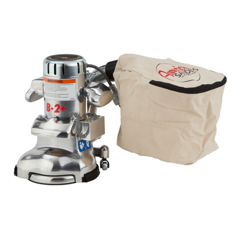
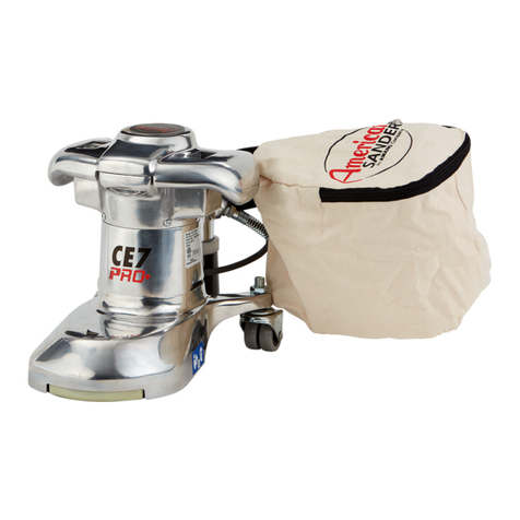
The American B-2 is specifically designed for finishing floor edges, stairs, and other hard-to-reach surfaces. The handle location and low center of
gravity make the American B-2 easy to operate.
The excellent cutting power comes from a powerful universal type motor. A motor that delivers maximum performance without slowing down or
overheating. Its exclusive two speed control when switched to hi-speed produces 3200 rpm for fast, rough sanding. At low speed, the American
B-2 operates at 2800 rpm for fine, finish sanding. A non-marking disc guard protects the rubber pad, permitting the edger to work right up to the
baseboard or wall.
Also standard is a convenient built-in headlight. Powerful fan and sanding disc housing design provides efficient dust pickup. Plus an easy to
remove dust pipe that makes cleaning a quick and simple task.
1-Powerful Universal Motor
2-On-Off Heavy Duty Switch
3-Comfortable Operating Handles
4-Built-In Headlight (07127A)
5-Aluminum Alloy Casting
6-Balanced Sanding Disc for perfectly
matched job
7-Non-Marking Roller Guard
8-Non-Marking Swivel Type Casters
9-High Low Switch
*-Hardened Steel Alloy Pinon and Drive Gear
*-Powerful Vacuum Fan for effecient dust
pickup
revised 3/13
1
2
3
4
5
6
7
8
9
SPECIFICATIONS
Model 07127A 07096A 07128A
Electrical
Requirements
115V ~, 60 Hz / 12.0A, 1.3 kW 230V ~, 25 - 60 Hz 230V ~, 50 - 60 Hz / 6.0A, 1.3 kW
Frame Aluminum Aluminum Aluminum
Disc Heavy duty steel precision balanced, 7”
dia. 2800 rpm low speed, 3200 rpm high
speed, heat resistant rubber pad
Heavy duty steel precision balanced,
7” dia. 2800 rpm low speed, 3200 rpm
high speed, heat resistant rubber pad
Heavy duty steel precision balanced,
7” dia. 2800 rpm low speed, 3200 rpm
high speed, heat resistant rubber pad
Gears Hardened steel alloy pinion and
manganese bronze drive gear.
Hardened steel alloy pinion and
manganese bronze drive gear.
Hardened steel alloy pinion and
manganese bronze drive gear.
Bearings Sealed ball bearings, lifetime lubricated. Sealed ball bearings, lifetime lubricated. Sealed ball bearings, lifetime lubricated.
Switch Positive action, on-off toggle. Positive action, on-off toggle. Positive action, on-off toggle.
Dust Collector Powerful vacuum fan, full aluminum skirt Powerful vacuum fan, full aluminum
skirt
Powerful vacuum fan, full aluminum
skirt
Cord 25’ 25’ 25’
Height (overall) 13-1/2” 13-1/2” 13-1/2”
Diameter 9-1/8” 9-1/8” 9-1/8”
Disc Diameter 7” 7” 7”
Weight 32 lbs. 32 lbs. 32 lbs.
Shipping Weight 46 lbs. 46 lbs. 46 lbs.
Warranty 1 year limited 1 year limited 1 year limited
EN
ENGLISH
-6- FORM NO. 70896A Clarke®American Sanders Operator's Manual (EN) - American B2
Machine Set-up
This sanding machine is designed to be operated with a
remote vacuum dust collection sytem or with the included
dust bag.
Preparing Remote Vacuum Dust Collection Sytems
To prepare the machine for remote vacuum dust collection
systems that have a 2" hose end, follow this procedure:
1. Install 2" hose end (figure 1, A) directly over the ex-
haust tube (figure 1, B).
2. The exhaust tube can be rotated for optimum conve-
nience.
To prepare the machine for remote vacuum dust collection
systems that have a 1 ½" hose end, follow this procedure:
1. Install the 2" x 1½" hose end adaptor (Part No.
30563A) (figure 1, C) over the exhaust tube (figure 1,
B).
2. Insert 1 ½" hose end (figure 1, D) into the adaptor
(figure 1, C).
NOTE: Start the remote vacuum collection system
before operation.
Preparing to use the included dust bag
To prepare the machine for use with the included dust bag
(Part No. 53544B), follow this procedure:
1. Install the dust bag by pressing the end onto the ex-
haust tube until the ring locks into the groove (figure
2). This is best done by pressing on the back of the
bag opening with the palm of your hand.
2. The exhaust tube can be rotated for optimum conve-
nience.
3. To remove the dust bag from the exhaust tube, pry
up the end of the bag opening to partially release the
internal rib from the groove, then pull.
4. To empty the dust bag, unzip the disposal flap and
force contents out by inverting the bag.
NOTE: For best results, empty frequently. Follow all
warnings posted in this manual and on the dust bag.
Install the dust bag by
pressing the end onto the
exhaust tube until the ring
locks into the groove.
A
2" Hose from
vacuum system
(not included)
1.5" Hose from
vacuum system
(not included)
D
B
C
Exhaust Tube
(30563A) 2" Tube x 1.5" hose adaptor
Figure 1
Figure 2

EN
ENGLISH
Clarke®American Sanders Operator's Manual (EN) - American B2 FORM NO. 70896A - 7 -
Figure 3
Figure 4
HOW TO PREPARE THE MACHINE FOR OPERATION
How to Install the Sandpaper
NOTE: Use a sandpaper disc that has a 7" diameter and a
7/8hole in the center.
1. Put the machine upside down.
2. A special wrench is in the bracket behind the mo-
tor. Use the special wrench to remove the screw
and washer from the center of the sanding pad. See
Figure 3.
3. Put the sanding disc in position on the sanding pad.
4. Put the special washer and the holding screw in posi-
tion in the center of the sanding pad.
5. Put one hand on the sandpaper. Using the special
wrench, turn the screw clockwise with the other hand.
Make sure the screw is tight. See Figure 4.
6. Return machine to upright position.
WARNING: Serious injury could occur when attempting
to replace abrasive while machine is con-
nected to power supply. Always disconnect
power before installing abrasive.
CAUTION: Gearbox damage could result from ma-
chine resting upside down for extended
periods of time. Lubricant may drain from
gearbox. Always return machine to upright
position after installing abrasive.

EN
ENGLISH
-8- FORM NO. 70896A Clarke®American Sanders Operator's Manual (EN) - American B2
Sanding Cuts and Sandpaper
Initial Cut
The purpose of the initial cut is to remove old finish and gross imperfections on the floor surface. A coarse
abrasive should be used. If the surface is severely damaged by deep scratches, pre-existing dwell marks,
uneven planks, etc., it may be necessary to sand across or diagonally to the grain to restore evenness to the
surface. If these conditions are not present, the initial cut should be done in the direction of the grain.
If glazing, loading, or burning takes place immediately into an initial cut, select a coarser abrasive. If this
should occur during an initial cut, the abrasive has dulled and must be replaced.
Final Cuts
The purpose of a finishing cut is to remove the scratches produced during the initial cut. Use a fine (60 - 80
grit) grain abrasive.
If the surface remains rough after a finishing cut, it may be necessary to use an even finer grain of abrasive
(80 - 100 grit). Care should be taken in selecting the grit size of the abrasive. A very fine grain will close the
pores on a wood floor making admission of a stain difficult.
If glazing or burning should occur immediately into a finishing cut, increase pace. If it should occur during a
finishing cut, the abrasive has dulled and must be replaced.
revised 7/12

EN
ENGLISH
Clarke®American Sanders Operator's Manual (EN) - American B2 FORM NO. 70896A - 9 -
HOW TO OPERATE THE MACHINE
DANGER: Failure to remove the electrical plug from
the electrical outlet before attempting any
service or maintenance could result in elec-
trocution or severe injury. Always unplug
the machine before attempting any service.
Never leave machine unattended while
plugged in.
To operate the machine follow this procedure:
1. Move the machine to the location of your work.
2. Connect the extension cord to the short power cord
on the machine. See figure 5.
3. Connect the other end of the extension cord to the
power supply outlet.
4. Put the variable speed switch in the "HI" position
(1). See figure 6. After reaching full speed, put the
switch in the "LO" position if low speed is needed.
NOTE: The high speed operation is for fast wood removal.
For finish custs and custom work, use the low speed opera-
tion.
5. Tilt the machine back so that the sandpaper disc
does not touch the floor See (1) in Figure 7. Hold
both handles. See (2) in Figure 7.
6. Put the On/Off switch in the "ON" position. See (3) in
Figure 7.
7. Keep the machine moving as you lower the sandpa-
per disc to the floor surface.
8. Do not press down on the machine. The weight of
the machine gives enough pressure for all types of
sanding.
MAINTENANCE
Figure 5
Figure 6
Figure 7
CAUTION: Maintenance and repairs performed by
unauthorized personnel could result in
damage or injury. Maintenance and re-
pairs performed by unauthorized person-
nel will void your warranty. Servicing of
these units must always be referred to
an authorized Clarke American Sanders
distributor.
NOTE: Do not store or rest the machine on the sand-
ing disc assembly. It may cause the disc to become
warped or cause it to be out of balance.
2
1

EN
ENGLISH
-10- FORM NO. 70896A Clarke®American Sanders Operator's Manual (EN) - American B2
MAINTENANCE (cont)
The Dust Control System
Remove the dust from the bag when the bag is 1/3
full or when the efficiency of the dust control system
decreases.
If the exhaust pipe gets an obstruction, follow this proce-
dure:
1. Remove the four screws that hold the exhaust
pipe to the housing. See figure 8.
2. Remove the obstruction from the exhaust pipe.
3. Install the exhaust pipe.
How to Adjust the Angle Of The Sandpaper Disc To
The Floor
The adjustment of the machine is correct when the front
part of the sandpaper disc makes contact with the floor.
To change the adjustment of the machine, follow
this procedure:
1. Using the special wrench, loosen the lock nut on
each caster. See (1) figure 9.
2. Loosen the jam nut. See (2) figure 9.
3. Raise or lower the casters as needed.
4. Tighten the jam nut on each caster.
5. Tighten the lock nut on each caster.
How To Replace The Light Bulb
To replace the light bulb, follow this procedure:
1. Remove the two screws that hold the light guard
to the housing. See figure 10.
2. Remove the light guard.
3. Remove the light bulb from the socket.
4. Install a new light bulb.
5. Put the lamp guard in position.
6. Install the two holding screws.
The Ventilation Plug
1. To clean the ventilation opening in the center of
the plug, remove the plug from the machine. With
the plug removed, also inspect the grease in the
gearbox. See figure 11.
Figure 8
Figure 10
Figure 11
Figure 9
1
2

EN
ENGLISH
Clarke®American Sanders Operator's Manual (EN) - American B2 FORM NO. 70896A - 11 -
Figure 12
Figure 13
Figure 14
MAINTENANCE
Lubrication
The machine is completely lubricated. The bearings and
gears in the gear unit have enough lubricant for approxi-
mately six months of normal operation. All other bearings
are sealed and have enough lubricant for the life of the ma-
chine. No lubricant is needed for the rotating disc guard.
How To Change The Lubricant In The Gearbox
To change the lubricant in the gearbox, follow this procedure:
1. Put the machine upside down on a bench.
2. Align one of the two holes in the rubber pad with one
of the three holes in the rotating disc guard.
3. Align both holes with one of the three screws in the
gear housing cover. Remove the screw from the gear
housing cover. See figure 12.
4. Align the holes with each of the other two screws, then
remove screws.
CAUTION!
Make sure no dust enters the gear box. Damage could
occur to the gear box.
5. Remove the cover from the gear housing.
6. Remove the old lubricant from the gearbox.
7. Add ten ounces of Clarke American Sanders lubricant
to the gearbox.
CAUTION!
To prevent damage to the motor, do not add more than
ten ounces of lubricant to the gearbox.
8. Using the three screws removed above, install the
cover on the gear housing.
9. Start the machine and let it run for 15 minutes. A small
amount of excess lubricant should flow out the vent
hole. If none appears it may be necessary to add ad-
ditional lubricant.
10. Wipe off excess lubricant and clear vent hole.
How To Check The Carbon Brushes
Depending on use, a set of brushes can be expected to last
250 hours and should be inspected sometime prior to that
time.
To check the brushes, follow this procedure:
1. Remove the motor cover. See figure 13.
2. Inspect the carbon brushes. Replace both brushes if
either brush has worn to 3/8" in length, or is worn to
the wear indicator. See figure 14.
3. To replace the brushes, disconnect the field wire
(A) from the brush holder (B). Then remove the two
screws and washers (C) securing the holder to the
motor housing. See figure 15.
Lubricants
Qty Part No.
1 Qt. 16610A
1 Gal. 16611A
Figure 15
A
A
B
B
C
C
C
C

EN
ENGLISH
-12- FORM NO. 70896A Clarke®American Sanders Operator's Manual (EN) - American B2
MAINTENANCE
How To Check The Carbon Brushes (cont)
4. Gently pry the holder down from the motor housing.
5. Rotate holder from beneath the motor housing and
lift out.
6. Disconnect the brush shunt wire from the holder.
For convenience, cut the terminal from the shunt
wire and remove brush.
7. To put in a new carbon brush, negotiate the ter-
minal on the shunt wire by the spring and brush
holder guide. Take care not to damage the spring.
See figure 16.
8. Depress the brush into the guide and connec the
shunt wire to the holder.
9. Depress the brush and insert the holder into the
motor housing.
10. Rotate holder beneath motor housing. Relax brush
against commutator.
11. Align posts on holder with holes in housing.
12. Gently pry the holder into the housing.
13. Reattach screws and washers.
14. Start up the machine, if sparking between either
brush and the commutator occurs, use a brush
seating stone on the commutator to promote full
engagement between the brushes and commutator.
15. Install the motor cover.
Figure 16

EN
ENGLISH
Clarke®American Sanders Operator's Manual (EN) - American B2 FORM NO. 70896A - 13 -
NOTES

-14- FORM NO. 70896A Clarke®American Sanders Manual del operador (ES) - American B2
ES
ESPAÑOL
LEA ESTE MANUAL
Este manual contiene información importante acerca del uso y la seguridad de la máquina. Si no lee el
manual antes de utilizar su máquina Clarke American Sanders o de intentar realizar los procedimientos
de reparación o mantenimiento de la misma, usted o el resto del personal podrían sufrir lesiones; asi-
mismo, podrían producirse daños a la máquina o a otras propiedades. Antes de utilizar la máquina, es
necesario recibir la capacitación adecuada en la operación de la misma. Si el operador de la máquina
no sabe leer en español, explíquele el manual exhaustivamente antes de que intente utilizarla.
Todas las indicaciones incluidas en este manual se ofrecen desde la posición del operador en la parte
posterior de la máquina.
Instrucciones de seguridad para el operador ............................ 15
Introducción y especificaciones de la máquina ......................... 17
Instalación de la máquina.......................................................... 18
Como Preparar la Máquina para el Funcionamiento................. 19
Cortes de lija y papel de lija...................................................... 20
Operación de la máquina .......................................................... 21
Mantenimiento .......................................................................... 21
Sección II Repuestos y manual de servicio......... 38-41
revised 3/13
ADVERTENCIA:
Los Productos a la venta en este Manual contienen, o pueden contener, productos químicos reconocidos por algunos gobiernos
(como el Estado de California, según lo indica en su Proposición 65, Ley de Advertencia Regulatoria) como causantes de cáncer,
defectos de nacimiento u otros daños reproductivos. En algunas jurisdicciones (incluido el Estado de California), los compradores
de estos Productos que los coloquen en servicio en un emplazamiento laboral o en un espacio de acceso público tienen la
obligación regulatoria de realizar determinados avisos, advertencias o divulgaciones respecto de los productos químicos contenidos
o posiblemente contenidos en los Productos utilizados en tal lugar. Es la responsabilidad del comprador conocer y cumplir con
todas las leyes y reglamentaciones relacionadas con el uso de estos Productos en tales entornos. El Fabricante niega toda
responsabilidad de informar a los compradores sobre requisitos específicos que pueden regir el uso de los Productos en tales
entornos.

Clarke®American Sanders Manual del operador (ES) - American B2 FORM NO. 70896A - 15 -
ES
ESPAÑOL
PELIGRO significa: Usted u otras personas pueden estar expuestos a sufrir lesiones personales,
inclusive la muerte si las indicaciones de PELIGRO que se encuentran en
esta máquina o en el manual de instrucciones se ignoran o no se tienen en
cuenta. Lea y respete todas las indicaciones de PELIGRO que se encuen-
tran en el manual de instrucciones y en la máquina.
ADVERTENCIA significa: Usted u otras personas pueden estar expuestos a sufrir lesiones
personales, si las indicaciones de ADVERTENCIA que se encuentran en
esta máquina o en el manual de instrucciones se ignoran o no se tienen en
cuenta. Lea y respete todas las indicaciones de ADVERTENCIA que se
encuentran en
el manual de instrucciones y en su máquina.
PRECAUCIÓN significa: La máquina u otros bienes pueden sufrir daños materiales si las
indicaciones de PRECAUCIÓN que se encuentran en la máquina o en el
manual de instrucciones se ignoran o no se tienen en cuenta. Lea y respete
todas las indicaciones de PRECAUCIÓN que se encuentran en el manual de
instrucciones y en la máquina.
PELIGRO: En caso de que no se lea el manual de instrucciones antes de operar este equipo de
lijado o realizar el mantenimiento del mismo podría resultar en que el operador u otras
personas en el área sufriesen lesiones personales y el equipo podría sufrir daños ma-
teriales. Lea y respete todas las indicaciones de seguridad que se encuentran en este
manual y en el equipo de lijado. Asegúrese que todas las etiquetas, calcomanías, adver-
tencias, precauciones e instrucciones estén adheridas a la máquina. Reemplace cual-
quier indicación que esté dañada o falte. Antes de utilizar el equipo, es necesario recibir
la capacitación adecuada en la operación del mismo. Si el operador no puede leer
este manual, explíqueselo exhaustivamente antes que intente utilizar este equipo.
PELIGRO: El lijado/acabado de pisos de madera puede crear un entorno que puede ser explosivo.
Se deberán tener en cuenta los siguientes procedimientos de seguridad:
• Los encendedores, las lámparas indicadoras y cualquier otra fuente de ignición
pueden provocar una explosión si se activan durante una sesión de lijado. Si es po-
sible, apague o retire por completo todas las fuentes de ignición del área de trabajo.
• Las áreas de trabajo que estén muy poco ventiladas pueden crear un entorno explo-
sivo cuando se encuentran determinados materiales combustibles en la atmósfera: por
ejemplo, solventes, diluyentes, alcoholes, combustibles, ciertos acabados, polvo de
madera y otros materiales combustibles. El equipo de lijado de pisos puede provocar
la combustión de los materiales y vapores inflamables . Lea la etiqueta del fabricante
sobre todas las sustancias químicas utilizadas para determinar su combustibilidad.
Mantenga el área de trabajo bien ventilada.
• Pueden producirse una combustión espontánea o una explosión cuando se trabaja
con polvo de lijado. El polvo de lijado puede auto-encenderse, provocando lesiones
personales y daños materiales. Deshágase del polvo de lijado de una manera ad-
ecuada. Vacíe siempre el polvo de lijado dentro de un recipiente de metal que esté
localizado fuera del edificio.
• Extraiga el contenido de la bolsa de polvo cuando la misma esté llena a 1/3. Extraiga
el contenido de la bolsa de polvo cada vez que termine de usar el equipo. Nunca deje
la bolsa sin vigilancia cuando haya polvo de lijado en la misma.
• No vacíe el contenido de la bolsa de polvo en el fuego.
• Golpear un clavo cuando se lija puede causar chispas y crear una explosión o un
incendio. Utilice siempre un martillo y perfore para avellanar todos los clavos antes de
lijar los pisos.
INSTRUCCIONES DE SEGURIDAD PARA EL OPERADOR

-16- FORM NO. 70896A Clarke®American Sanders Manual del operador (ES) - American B2
ES
ESPAÑOL
PELIGRO: La operación de equipo de lijado parcialmente ensamblado podría provocar que el operador o las
personas en el área de trabajo sufriesen lesiones, y también podría causar daños materiales al
equipo o a otro bienes.
• No opere este equipo a menos que esté totalmente ensamblado y que todas las protecciones,
puertas y tapas estén bien aseguradas en su lugar.
• Mantenga todas las sujeciones apretadas.
• Mantenga todos los ajustes dentro de las especificaciones del fabricante.
PELIGRO: Las partes móviles de este equipo de lijado pueden causar lesiones al operador o a las personas que
se encuentren en el área de trabajo.
• Mantenga las manos, los pies y la vestimenta suelta alejados de todas las partes móviles.
• No cambie ni ajuste el abrasivo mientras el equipo de lijado esté en funcionamiento.
• No realice ningún servicio de reparación o mantenimiento al equipo de lijado mientras esté en
funcionamiento.
PELIGRO: Este equipo de lijado requiere un suministro de electricidad. El uso inadecuado podría provocar una
descarga eléctrica o un incendio.
• Conecte únicamente a un suministro eléctrico que coincida con lo que se muestra en la placa de
identificación del equipo.
• No utilice este equipo de lijado sobre un circuito eléctrico sin conexión a tierra. Consulte con un
electricista si sospecha que el circuito no está adecuadamente conectado a tierra.
• No utilice este equipo de lijado con un cable eléctrico dañado. Inspecciones antes de cada uso.
• Evite golpear el cable eléctrico con el abrasivo. Eleve siempre el cable eléctrico sobre el equipo
de lijado.
• No utilice el cable eléctrico para mover el equipo.
• Desconecte el suministro eléctrico antes de realizar un servicio de reparación o mantenimiento
al equipo.
ADVERTENCIA: Si no se utilizan los dispositivos de protección personal correctos mientras se realiza el lijado, el
operador o cualquier persona en el área de trabajo pueden sufrir lesiones. Utilice siempre protección
respiratoria, ocular y auditiva mientras realice una operación de lijado.
ADVERTENCIA: Pueden producirse lesiones personales si se aplica potencia al equipo con el interruptor de aliment-
ación ya situado en la posición “ON” (Encendido). Asegúrsese siempre de que el interruptor de
alimentación esté en la posición “OFF” (Apagado) antes de conectar la fuente de alimentación.
PRECAUCIÓN: El mantenimiento y las reparaciones realizados por personal no autorizado podrían producir daños
materiales o lesiones personales. El mantenimiento y las reparaciones realizadas por personal no
autorizado anularán su garantía. El mantenimiento y las reparaciones de esta unidad siempre deben
ser realizados por un distribuidor autorizado de Clarke American Sanders.
PRECAUCIÓN: Si utiliza este equipo para desplazar otros objetos o para subirse al mismo se pueden producir lesiones
o daños. No utilice este equipo como escalera ni como mueble. No se suba al equipo.
PRECAUCIÓN: Si el equipo no se guarda correctamente en un edificio sin humedad podría resultar dañado. Guarde
el equipo en un lugar seco.
PRECAUCIÓN:Se puede causar un daño grave al piso si el equipo de lijado se deja funcionando en un lugar mientras
el disco de lijado está en contacto con el piso. Para evitar que se dañe el piso, cuando baje o eleve
el disco de lijado, hágalo en el menor tiempo posible. Siempre lije con un movimiento constante.

Clarke®American Sanders Manual del operador (ES) - American B2 FORM NO. 70896A - 17 -
ES
ESPAÑOL
INTRODUCCIÓN Y ESPECIFICACIONES DE LA MÁQUINA
American B-2 ha sido específicamente diseñada para el acabado de bordes de pisos, escaleras y otras superficies de difícil alcance. La ubicación
de la manija y el bajo centro de gravedad hacen que American B-2 sea de fácil operación.
Su excelente poder de corte proviene de un poderoso motor de tipo universal, un motor que proporciona un máximo rendimiento sin funcionar con
lentitud ni recalentarse. Su exclusivo control de dos velocidades proporciona 3200 rpm para un lijado rápido, en tosco, cuando se lo coloca en alta
velocidad. A baja velocidad, American B-2 funciona a 2800 rpm para proporcionar un lijado de acabado fino. Un protector del disco, que no deja
marcas, resguarda la almohadilla de goma, permitiendo que la canteadora trabaje justo hasta el zócalo o la pared.
La unidad cuenta con la ventaja de una luz delantera estándar incorporada, instalada en fábrica. El diseño incluye un poderoso ventilador y
alojamiento del disco de lijado para proporcionar una efectiva recolección del polvo. Además de un tubo de polvo de fácil extracción que hace de la
limpieza una tarea rápida y simple.
ESPECIFICACIONES
Modelo 07127A 07096A 07128A
Requerimientos
Eléctricos
115V ~, 60 Hz
12.0A, 1.3 kW
230V ~, 25 - 60 Hz 230V ~, 50 - 60 Hz
6.0A, 1.3 kW
Bastidor Aluminio Aluminio Aluminio
Disco De precisión de acero reforzado
balanceado, 7” de diámetro 2800 rpm
baja velocidad, 3200 rpm alta velocidad,
resistente al calor almohadilla de goma.
De precisión de acero reforzado
balanceado, 7” de diámetro 2800 rpm
baja velocidad, 3200 rpm alta velocidad,
resistente al calor almohadilla de goma.
De precisión de acero reforzado
balanceado, 7” de diámetro 2800 rpm
baja velocidad, 3200 rpm alta velocidad,
resistente al calor almohadilla de goma.
Engranajes Piñón de aleación de acero cementado
y engranaje de transmisión de bronco
manganoso.
Piñón de aleación de acero cementado
y engranaje de transmisión de bronco
manganoso.
Piñón de aleación de acero cementado
y engranaje de transmisión de bronco
manganoso.
Cojinetes Cojinetes esféricos sellados, lubricación
de larga duración.
Cojinetes esféricos sellados, lubricación
de larga duración.
Cojinetes esféricos sellados, lubricación
de larga duración.
Interruptor Acción positiva, conecta/ desconecta Acción positiva, conecta/ desconecta Acción positiva, conecta/ desconecta
Colector de polvo Poderoso ventilador de aspiración faldón
de aluminio
Poderoso ventilador de aspiración
faldón de aluminio
Poderoso ventilador de aspiración
faldón de aluminio
Cable 25’ 25’ 25’
Altura (total) 13½” 13½” 13½”
Diámetro 91/8” 91/8” 91/8”
Diámetro de
disco
7” 7” 7”
Peso 32 libras 32 libras 32 libras
Peso del envio 46 libras 46 libras 46 libras
Garantía limitada por 1 año limitada por 1 año limitada por 1 año
revised 3/13
1
2
3
4
5
6
7
8
9
1-Poderoso motor universal
2-Interruptor de encendido / apagado
reforzado
3-Confortables manijas de operación
4-Luz delantera incorporada (07127A)
5-Fundición de aleación de aluminio
6-Disco de lijado balanceado para un trabajo
perfectamente equilibrado
7-Protector de rodillos que no deja marcas
8-Ruedas de roldana pivotantes que no
dejan marcas
9-Interruptor de alta y baja
*-Piñón y engranaje de transmisión de
aleación de acero cementado
*-Poderoso ventilador de aspiración, para
una eficiente recolección del polvo

-18- FORM NO. 70896A Clarke®American Sanders Manual del operador (ES) - American B2
ES
ESPAÑOL
Instalación de la máquina
Esta lijadora está diseñada para utilizarse con un sistema
colector de polvo remoto mediante vacío o con la bolsa de
polvo incluida.
Preparación de los sistemas colectores de polvo remo-
tos mediante vacío
Si desea preparar la máquina para sistemas colectores de
polvo remotos mediante vacío que tengan un extremo de
manguera de 2", siga este procedimiento:
1. Instale e extremo de manguera de 2" (figura 1, A) di-
rectamante sobre el tubo de escape (figura 1, B).
2. El tubo de escape puede girarse para mayor comodi-
dad.
Si desea preparar la máquina para sistemas colectores de
polvo remotos mediante vacío que tengan un extremo de
manguera de 1 ½", siga este procedimiento:
1. Instale el adaptador del extremo de manguera de 2" x
1½" (Node pieza 30563A) (figura 1, C) sobre el tubo de
escape (figura 1, B).
2. Inserte el extremo de manguera de 1½" (figura 1, D) en
el adaptador (figura 1, C).
NOTA: Ponga en marche el sistema colector remoto
mediante vacío antes de encender la máquina.
Preparación para usar la bolsa de polvo incluida
Si desea preparar la máquina para su uso con la bolsa de
polvo incluida (Node pieza 53544B), siga este procedimiento.
1. Instale la bolsa de recolección de polvo presionando el
extremo del tubo de escape hasta que el anillo encaje
dentro de la ranura (figura 2). El mejor modo de hacer
esto es presionando la parte posterior de la abertura de
la bolsa con la palma de su mano.
2. El tubo de escape puede girarse para mayor comodi-
dad.
3. Para retirar la bolsa de polvo del tubo de escape, haga
palanca hacia arriba en el extremo de la abertura de la
bolsa para liberar parcialmente el saliente interno de la
ranura, y después tire.
4. Para vaciar la bolsa de polvo, abra la aleta de vaciado y
saque sus contenidos dando la vuelta a la bolsa.
NOTA: Para lograr los mejores resultados, vacíe fre-
cuentemente. Siga todas las advertencias incluidas en
el manual y en la bolsa de polvo.
A
MANGUERA DE 2"
DEL SISTEMA DE
ASPIRACIÓN (NO
INCLUIDO)
MANGUERA DE
1.50" DEL SISTEMA
DE ASPIRACIÓN
(NO INCLUIDO)
D
B
C
TUBO DE ESCAPE
30563A TUBO DE 2" X
ADAPTADOR DE MANGUERA DE 1.50"
Figura 1
Figura 2
INSTALE LA BOLSA DE
RECOLECCIÓN DE POLVO
PRESIONANDO EL EXTREMO DEL
TUBO DE ESCAPE HASTA QUE EL
ANILLO ENCAJE DENTRO DE LA
RANURA.

Clarke®American Sanders Manual del operador (ES) - American B2 FORM NO. 70896A - 19 -
ES
ESPAÑOL
Figura 3
Figura 4
COMO PREPARAR LA MÁQUINA PARA EL FUNCIO-
NAMIENTO
Instalación del papel de lija
NOTA: Use un disco de papel de lija de 7" de
diámetro y un orificio de 7/8 en el centro.
1. Dé vuelta la máquina.
2. Hay una llave especial en el soporte detrás del
motor. Use la llave especial para sacar el tornillo
y la arandela del centro de la almohadilla de
lijado. Consulte la Figura 3.
3. Ponga el disco de lijado en posición sobre la
almohadilla de lijado.
4. Ponga la arandela especial y el tornillo de su-
jeción en posición en el centro de la almohadilla
de lijado.
5. Ponga una mano sobre el papel de lija. Con la
llave especial, gire el tornillo en sentido horario
con la otra mano. Asegúrese de que el tornillo
quede apretado. Consulte la Figura 4.
ADVERTENCIA: Podrian ocurrir lesiones graves
cuando intente reemplazar el abrasivo
mientras la máquina está conectada
al suministro elétrico. Siempre
desconecte el suministro elétrico antes
de instalar el abrasivo.
PRECAUCIÓN: Los engranajes podrían resul-
tar dañados si la máquina quedara al
revés por períodos de tiempo prolon-
gados. El lubricante podría drenar
de los engranajes. Siempre vuelva a
colocar la máquina en posición vertical
luego de instalar el abrasivo.

-20- FORM NO. 70896A Clarke®American Sanders Manual del operador (ES) - American B2
ES
ESPAÑOL
Cortes de lija y papel de lija
Corte inicial
El propósito del corte inicial es sacar el acabado viejo y las imperfecciones mayores de la superficie del piso.
Se debe usar un abrasivo grueso. Si la superficie está muy dañada por rayones profundos, marcas preexis-
tentes, tablones desiguales, etc., puede ser necesario lijar horizontalmente o diagonalmente al veteado para
restaurar la uniformidad de la superficie. Cuando no se den las condiciones anteriores, el corte inicial debe
realizarse en la dirección del veteado de la madera.
Si un corte inicial aparece inmediatamente glaseado, cargado o quemado, seleccione un abrasivo más
grueso. Si esto ocurriera durante un corte inicial significa que el abrasivo se ha desgastado y deberá ser
reemplazado.
Cortes finales
El propósito de un corte de acabado es eliminar los rayones producidos durante el corte inicial. Utilice un
abrasivo de grano fino (60- 80 granos) .
Si la superficie permanece áspera después de un corte de acabado, puede ser necesario utilizar un abrasivo
de grano aún más fino (80 - 100 granos). Se deberá tener cuidado al seleccionar el tamaño del grano del
abrasivo. Un grano muy fino cerrará los poros sobre el piso de madera dando lugar a problema de man-
chas.
Si un corte de acabado apareciera inmediatamente glaseado o quemado, aumente el ritmo. Si esto ocurriera
durante un corte final, significa que el abrasivo se ha desafilado y deberá cambiarse.
revised 7/12
Other manuals for 07127A
1
This manual suits for next models
2
Table of contents
Languages:
Other Clarke Edger manuals

Clarke
Clarke 07097A User manual

Clarke
Clarke American Sanders 07011A User manual

Clarke
Clarke American B-2 User manual

Clarke
Clarke Super 7R Installation and operating manual

Clarke
Clarke American B-2 User manual

Clarke
Clarke 07127A User manual

Clarke
Clarke B2 7" Spinner Edge 07072A User manual

Clarke
Clarke Super 7R User manual

Clarke
Clarke 07170A User manual

Clarke
Clarke Super E User manual