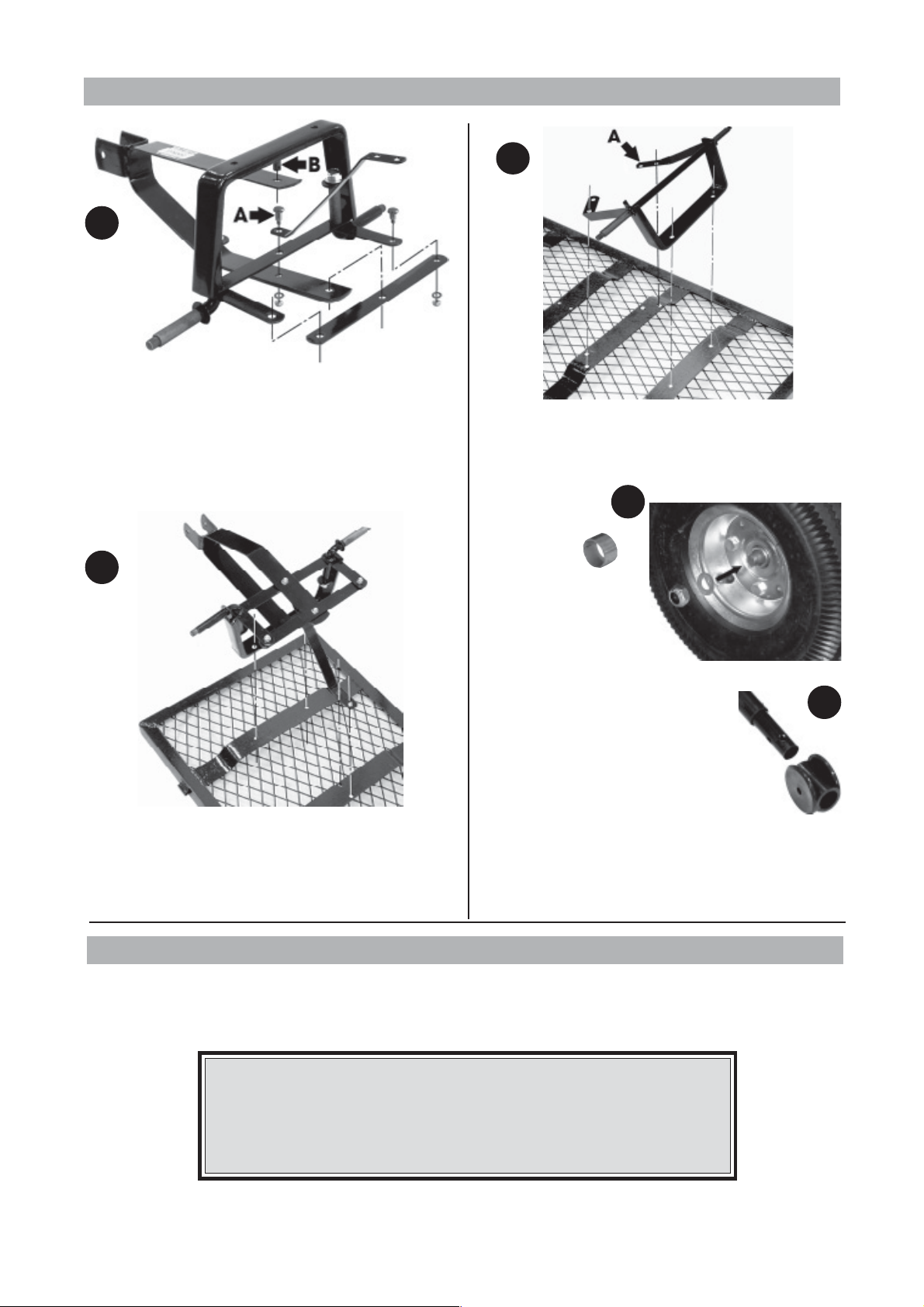
0104
Thank you for purchasing this CLARKE Towable/Drop Sided Trolley.
Before using the device, please read this manual thoroughly and carefully follow all instructions given. This is for your own safety
and that of others around you, and is also to help you achieve a long and trouble free service from your new truck.
SAFETY PRECAUTIONS
WARNING!
Read these safety instructions before using the equipment.
BEFORE attempting to transport any load, ensure you are physically able to do so.
DO NOT exceed the maximum working load for the truck - 150kg
DO NOT leave the truck on a gradient without first securely chocking the wheels.
DO NOT allow children to play with or ride on the truck.
DO NOT leave the truck on any steep inclines.
NEVER use the truck if any of the tyres are deflated....inflate them immediately.
NEVER use the truck to transport Personnel or animals.
ALWAYS inspect the truck for signs of wear or damage before using.
ALWAYS ensure the load is evenly distributed and is perfectly stable.
CLARKE GUARANTEE
This CLARKE product is guaranteed against faulty manufacture for a period of 12 months from
the date of purchase. Please keep your receipt as proof of purchase.
This guarantee is invalid if the product is found to have been abused or tampered with in any
way, or not used for the purpose for which it was intended.
Faulty goods should be returned to their place of purchase, no product can be returned to us
without prior permission.
This guarantee does not affect your statutory rights.
Model : GT - 2
Part No : 3400180
Towable,Drop Sided Garden Trolley
Towable,Drop Sided Garden Trolley