manuals.online logo
Brands
  1. Home
  2. •
  3. Brands
  4. •
  5. EGO
  6. •
  7. Garden Machinery Accessories
  8. •
  9. EGO AEB0800 User manual

EGO AEB0800 User manual

WARNING: Do not attempt to straighten or weld a bent or cracked blade. Such a blade may break
and it must be replaced. Only the EGO replacement blade AEB0800 is guaranteed to be compatible with
the Edger Attachment EA0800.
NOTICE: Replace the blade if its length is no longer sufficient to maintain the necessary ground clearance
and obtain the required depth of cut.
WARNING: Always protect your hands by wearing heavy gloves or wrapping the blade with rags or
other materials when performing any maintenance on the edger blade.
Removing the blade
1. Stop the motor and remove the battery pack.
2. Lay the edger on its back so that the blade is facing upwards.
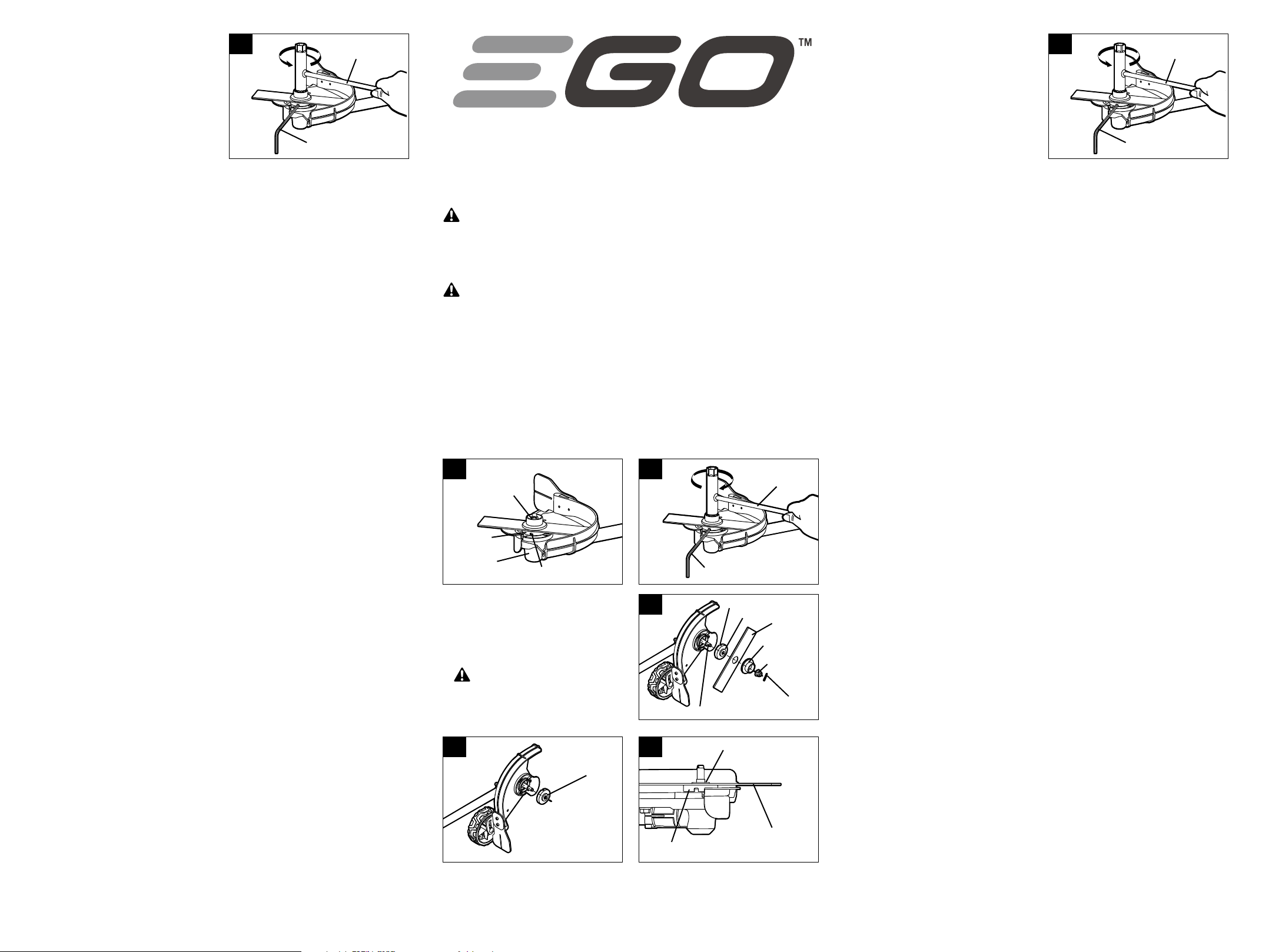
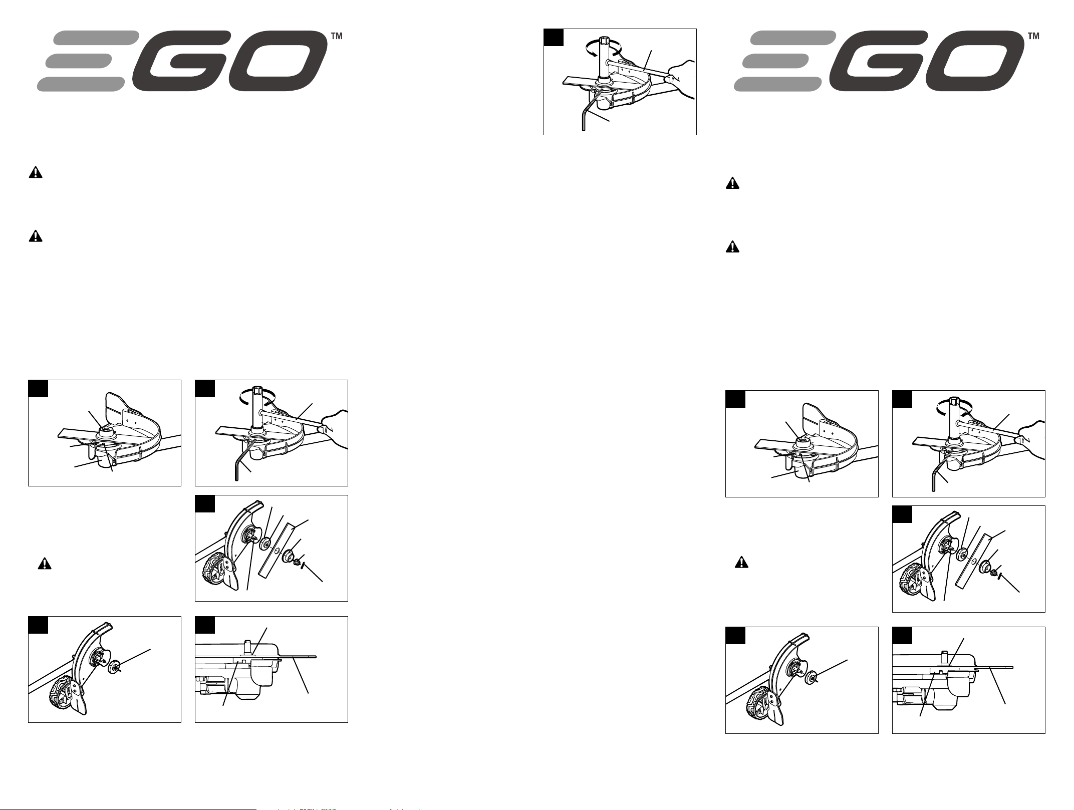
3. Wear protective gloves. Use a needle nose pliers (not included) to remove the cotter pin from the
motor shaft (Fig. 1).
4. Rotate the blade to align the slot in the flange with the hole in the gear case (Fig. 1).
5. Insert the hex wrench provided into the aligned holes to act as a stabilizer. Use the multi-function
wrench provided to loosen the nut CLOCKWISE (Fig. 2).
6. Remove the nut, the outer flange, the blade and the inner flange from the motor shaft (Fig. 3). Check
and replace them if they are worn.
Installing the blade
1. Position the inner flange removed in step 6
of the “Removing the blade” section onto the
motor shaft with the bulge of the inner flange
facing outwards (Fig. 4).
2. Install the new blade onto the inner flange.
WARNING: The bulge of the inner flange
must engage the blade’s mounting hole
(Fig. 5). There should not be any clearance
between the blade and the inner flange flat
surface.
AVERTISSEMENT : Ne tentez pas de redresser ni de souder une lame tordue ou fissurée. Une telle
lame doit être remplacée, car elle pourrait se briser. Il est recommandé de remplacer la lame uniquement
par une lame de coupe-bordure EGO; consultez la section « Lame recommandée ».
AVIS : Remplacez la lame si sa longueur n’est plus suffisante pour maintenir le dégagement nécessaire
au-dessus du sol et obtenir la profondeur de coupe voulue.
AVERTISSEMENT : Protégez-vous toujours les mains en portant des gants épais ou en recouvrant
la lame de chiffons ou d’autres matériaux lorsque vous entretenez celle-ci.
Retrait de la lame
1. Arrêtez le moteur et enlevez le blocpile.
2. Déposez le coupe-bordure sur le dos de façon à ce que la lame soit orientée vers le haut.
3. Portez des gants de protection. Utilisez une pince à bec effilé (non incluse) pour retirer la goupille
d’arrêt de l’arbre du moteur (Fig. 1).
4. Tournez la lame pour aligner la fente dans le collet sur le trou du boîtier d’engrenage (Fig. 1).
5. Insérez la clé hexagonale fournie dans les trous alignés pour qu’elle agisse comme stabilisateur.
Utilisez la clé multifonction fournie pour desserrer l’écrou DANS LE SENS DES AIGUILLES D’UNE
MONTRE (Fig. 2).
6. Retirez l’écrou, le collet extérieur, la lame et le collet intérieur de l’arbre du moteur (Fig. 3).
Inspectez-les et remplacez-les s’ils sont usés.
Installation de la lame
1. Placez le collet intérieur retiré à l’étape 6 de
la section « Retrait de la lame » sur l’arbre du
moteur, surface bombée vers l’extérieur(Fig. 4).
2. Installez la nouvelle lame sur le collet intérieur.
AVERTISSEMENT : La surface bombée du
collet intérieur doit s’enclencher dans le trou
de montage de la lame (Fig. 5). Il ne devrait
pas y avoir d’espace entre la lame et la surface
plane du collet intérieur.
3. Mount the outer flange and the nut
onto the shaft, and pre-tighten the nut
COUNTERCLOCKWISE by hand.
4. Rotate the blade to align the slot in the flange
with the hole in the gear case (Fig. 1)
5. Insert the hex wrench provided into the aligned
holes to act as a stabilizer. Use the multi-
function wrench provided to tighten the nut
COUNTERCLOCKWISE securely onto the shaft
(Fig. 6).
6. Insert a new cotter pin into the hole in the
motor shaft. Bent the two feet of the pin in
opposite directions with a needle nose pliers (not included) (Fig. 1).
OPERATOR’S MANUAL
REPLACING THE BLADE
MODEL NUMBER AEB0800
The blade is exclusively compatible with EGO Power Head System Edger Attachment EA0800
GUIDE D’UTILISATION
REMPLACEMENT DE LA LAME
NUMÉRO DE MODÈLE AEB0800
La lame est compatible exclusivement avec
EGO POWER+ COUPE-BORDURE AMOVIBLE EA0800.
1 2 3
6
Stabilizer
Multi-function
Wrench Provided
1
Cotter Pin
Inner Flange
Gear Case
Aligned Shaft-locking Holes
2Multi-function
Wrench Provided
Stabilizer
1
Goupille d’arrêt
Collet intérieur
Boîtier
d’engrenage Trous de verrouillage alignés
2Clé multifonction
fournie
Stabilisateur
4
Bulge Outwards
4Surface bombée
vers l’extérieur
5Bulge of the inner flange
engaging the blade
Blade
Inner Flange
5Surface bombée du collet
intérieur enclenché dans
la lame
Lame
Collet intérieur
3
Motor Shaft
Slot in the Inner Flange
Inner Flange
Blade
Outer Flange
Nut
Cotter Pin
3
Arbre du moteur
Fente dans le collet intérieur
Collet intérieur
Lame
Collet extérieur
Écrou
Goupille d’arrêt
4 5 6
3. Fixez le collet extérieur et l’écrou sur l’arbre,
puis serrez partiellement l’écrou à la main
DANS LE SENS CONTRAIRE DES AIGUILLES
D’UNE MONTRE.
4. Faites tourner la lame pour aligner la
fente dans le collet avec le trou du boîtier
d’engrenage (Fig. 1).
5. Insérez la clé hexagonale fournie dans les
trous alignés pour qu’elle agisse comme
stabilisateur. Utilisez la clé multifonction
fournie pour serrer fermement l’écrou sur
l’arbre DANS LE SENS CONTRAIRE DES
AIGUILLES D’UNE MONTRE (Fig. 6).
6. Insérez une nouvelle goupille d’arrêt dans le trou de l’arbre du moteur. Pliez les deux pieds de la
goupille dans des directions opposées avec une pince à bec effilé (non incluse)(Fig. 1).
6
Stabilisateur
Clé multifonction
fournie
ADVERTENCIA: No intente enderezar o soldar la cuchilla si está doblada o agrietada. Puede
romperse y será necesario reemplazarla. Recomendamos que reemplace solo con la cuchilla para
bordeadora EGO, consulte la sección “cuchilla recomendada”.
AVISO: Reemplace la cuchilla si su largo ya no es suficiente para mantener el espacio libre con la tierra y
obtener la profundidad requerida de corte.
ADVERTENCIA: Protéjase siempre las manos con guantes resistentes o envuelva la cuchilla con
paños u otro material al realizar el mantenimiento de la cuchilla de la bordeadora.
Cómo Retirar La Cuchilla
1. Detenga el motor y retire el paquete de baterías.
2. Coloque la bordeadora sobre su parte posterior de modo que la cuchilla esté orientada hacia arriba.
3. Use guantes de protección. Use unas pinzas de punta fina (no se incluyen) para retirar el pasador de
bloqueo del mango del motor (Fig. 1).
4. Rote la cuchilla para alinear la ranura en la brida con el orificio en la caja de engranajes (Fig. 1).
5. Inserte la llave hexagonal provista en los orificios alineados para que actúe como estabilizador.
Utilice la llave multiuso provista para aflojar la tuerca en dirección de las manecillas del reloj (Fig. 2).
6. Retire la tuerca, la brida externa, la cuchilla y la brida interna del eje del motor (Fig. 3). Revíselas y
reemplácelas si están desgastadas.
Cómo instalar la cuchilla
1. Coloque la brida interna que retiró en el paso 6
de la sección “Cómo retirar la cuchilla” sobre
el eje del motor con el bombeo de la brida
interna mirando hacia afuera (Fig. 4).
2. Instale la cuchilla nueva en la brida interna.
ADVERTENCIA: El bulto de la brida
interna debe encajar en orificio de montaje
de la cuchilla (Fig. 5). No debe quedar ningún
espacio entre la cuchilla y la superficie plana
de la brida interna.
3. Instale la brida externa y la tuerca en el eje y
apriete la tuerca EN DIRECCIÓN CONTRARIA A
LAS MANECILLAS DEL RELOJ a mano.
4. Rote la cuchilla para alinear la ranura de la
brida con el orificio en la caja de engranajes
(Fig. 1)
5. Inserte la llave hexagonal provista en los
orificios alineados para que actúe como
estabilizador. Use la llave multiuso provista
para apretar la tuerca firmemente EN
DIRECCIÓN CONTRARIA A LAS MANECILLAS
DEL RELOJ sobre el eje (Fig. 6).
6. Inserte un pasador de fijación nuevo en el orificio en el eje del motor. Doble las dos patas del pasador
en direcciones opuestas con unas pinzas de punta fina (no se incluyen)(Fig. 1).
MANUAL DE FUNCIONAMIENTO
CÓMO REEMPLAZAR LA CUCHILLA
MODELO NÚMERO AEB0800
La cuchilla es exclusivamente compatible con
EGO POWER+ ACCESORIO PARA BORDEADORA EA0800.
6
Estabilizador
Llave multiuso
provista
1
Pasador de bloqueo
Brida interna
Caja de
engranajes Orificios alineados de
bloqueo del mango
2Llave multiuso
provista
Estabilizador
4
Bulto hacia el exterior
5Bulto de la brida interna
que encaja con la cuchilla
Cuchilla
Brida interna
3
Eje del motor
Ranura en la brida interna
Brida interna
Cuchilla
brida externa
Tuerca
Pasador de bloqueo

Other EGO Garden Machinery Accessories manuals

EGO AMS1000 User manual

EGO

EGO AMS1000 User manual

EGO AH3810 User manual

EGO

EGO AH3810 User manual

EGO BCA1200 User manual

EGO

EGO BCA1200 User manual

EGO AH1200 User manual

EGO

EGO AH1200 User manual

EGO AH1530 User manual

EGO

EGO AH1530 User manual

EGO EA0800 User manual

EGO

EGO EA0800 User manual

EGO PSA1000 User manual

EGO

EGO PSA1000 User manual

EGO ABP5200 User manual

EGO

EGO ABP5200 User manual

EGO STA1500 User manual

EGO

EGO STA1500 User manual

EGO STA1500 User manual

EGO

EGO STA1500 User manual

EGO POWER+ LINE AS1200E User manual

EGO

EGO POWER+ LINE AS1200E User manual

EGO BCA1200 User manual

EGO

EGO BCA1200 User manual

EGO POWER+ PTX5100 User manual

EGO

EGO POWER+ PTX5100 User manual

Popular Garden Machinery Accessories manuals by other brands

Toro 41250 installation instructions

Toro

Toro 41250 installation instructions

Craftsman 486.24278 Operator's manual

Craftsman

Craftsman 486.24278 Operator's manual

Makita ER400MP Original instruction manual

Makita

Makita ER400MP Original instruction manual

Stihl 4110 713 4100 manual

Stihl

Stihl 4110 713 4100 manual

Stihl AutoCut C 3-2 manual

Stihl

Stihl AutoCut C 3-2 manual

Echo shindaiwa Series instruction sheet

Echo

Echo shindaiwa Series instruction sheet

Makita EN424MP instruction manual

Makita

Makita EN424MP instruction manual

Stihl AUTOCUT 40-2 quick start guide

Stihl

Stihl AUTOCUT 40-2 quick start guide

Ryobi EXPAND-IT RY15526 Operator's manual

Ryobi

Ryobi EXPAND-IT RY15526 Operator's manual

Garten Meister GM HSA 710/510 Original instructions

Garten Meister

Garten Meister GM HSA 710/510 Original instructions

Baroness LM66 Series installation manual

Baroness

Baroness LM66 Series installation manual

manuals.online logo
manuals.online logoBrands
  • About & Mission
  • Contact us
  • Privacy Policy
  • Terms and Conditions

Copyright 2025 Manuals.Online. All Rights Reserved.