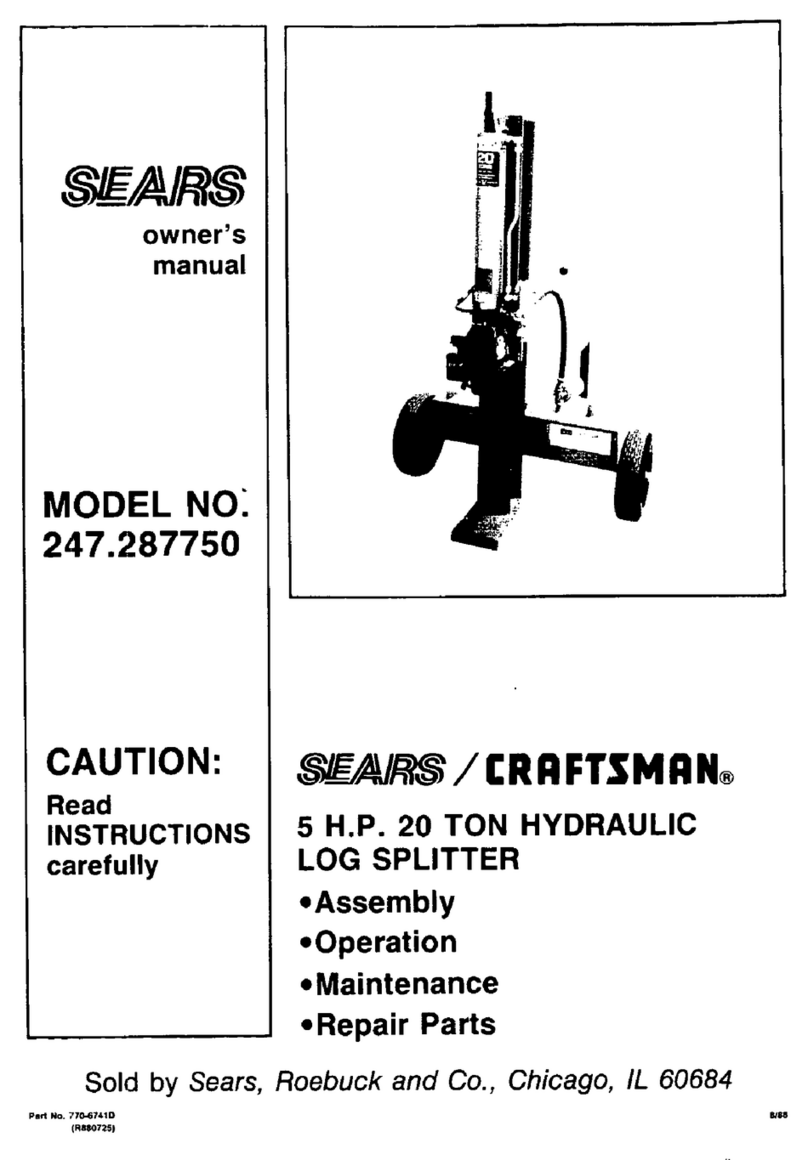
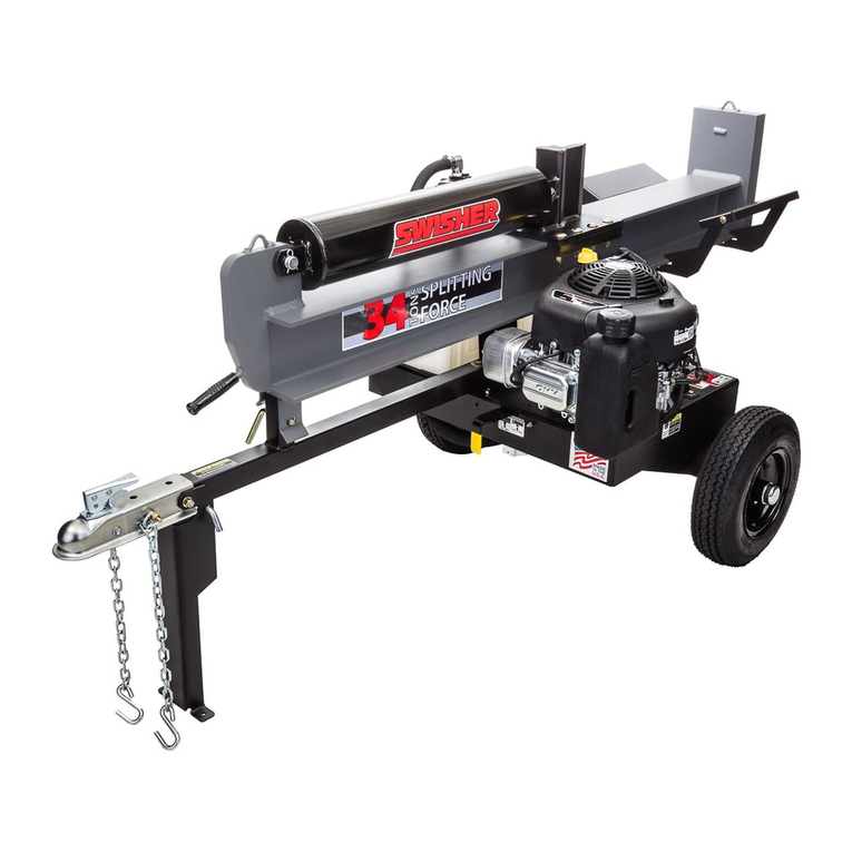
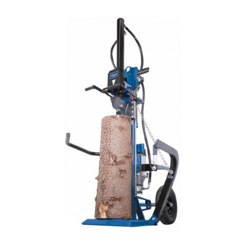
Clarke LOGBUSTER II Installation and operation manual

OPERATING & MAINTENANCE
INSTRUCTIONS
0201
LOGBUSTER II
(Electric Log Splitter)
Part No. 3402010
LOGBUSTER II

Congratulations on your choice of a Clarke Logbuster II. Please read this manual
thoroughly and carefully follow all insrtructions given. In doing so you will ensure
the safety of yourself and that of others around you, and achieve excellent results
and the best performance from the machine.
IMPORTANT
Before transporting, installing or operating the machine, you should read all
parts of this manual, paying particular attention to the specific safety
regulations. This manual is an integral part of the machine and must
accompany it even in the case of transfer of ownership.
Clarkes’ Logbuster II has been designed and manufactured in compliance with
the most recent European safety regulations with particular reference to the EN609
and EN60204.
The “ZHB” control systems have been designed and engineered so that the
operator is forced to work in the safety area without any possibility of inserting
hands or arms in dangerous areas.
GUARANTEE
This CLARKE product is guaranteed against faulty manufacture for a period of 12
months from the date of purchase. Please keep your receipt as proof of purchase.
This guarantee is invalid if the product is found to have been abused or tampered
with in any way, or not used for the purpose for which it was intended.
Faulty goods should be returned to their place of purchase, no product can be
returned to us without prior permission. This guarantee does not effect your
statutory rights.
Failure to comply in any way with these instructions, improper use of the machine,
extraordinary maintenance operations not carried out by skilled, authorised
personnel, removal of data plates or markings of any type, removal or tampering
with the guards and safety mechanisms of the machine or any other action not
expressly authorised, that may impair the active and passive safety systems of the
machine, shall relieve the manufacturer of all and any liability and may result in
serious injury and damage.
FEATURES
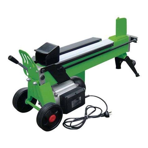
The Logbuster II is a portable log splitter, equipped with electric motor. The various
parts of the machine are shown in fig.1.
1 - Blade
2 - Oil tank
3 - Wheels for minor movements
4 - Electric motor
5 - Electric motor starter push-button
6 - Foot
7 - Support surface (not supplied)
8 - ZHB hydraulic control lever
9 - Log pusher and lifting handle
10 - Log retention brackets
2

SPECIFICATIONS
Length ................................................................... 765 mm
Width ..................................................................... 300 mm
Height ................................................................... 490 mm
Weight ................................................................... 35 Kg
Max. force ............................................................ 4 tons
Log capacity ....................................................... 36 cm
Hydraulic oil capacity ......................................... 2,6 Lt
Power Supply ....................................................... 230V 50Hz 1phase
Current .................................................................. 10 A
Power Rating ........................................................ 2 CV - 1,5 kW
Average noise ...................................................... <=71 dB(A) at lm.
(Protective ear defenders are not necessary)
Size of logs to be split
Figure 2 shows the maximum log size that can be split.
Please note that the diameter of the log is indicative: i.e.
A small log can be difficult to split if it has knots or a
particularly tough fibre. On the other hand, if the wood
has regular fibres, it is not difficult to split logs with
diameters greater than that shown in Figure 2.
It is important NOT to persist if the log does not split on the first attempt, as the pump
may be damaged by the oil overheating. This could occur when the machine is
made to work under maximum stress in an attempt to split excessively fibrous, knotty
wood or wet, green wood. Do not attempt to split a log for longer than 5 seconds
WARNING: THE LOGBUSTER II HAS BEEN DESIGNED AND MANUFACTURED
TO SPLIT LOGS OF THE SIZES RECOMMENDED. USE OF THE MACHINE FOR
ANY OTHER PURPOSE SHALL BE CONSIDERED IMPROPER.
Fig.2
Fig.1
3

GENERAL SAFETY RULES
WARNING:
As with all machinery, there are certain hazards involved with their operation and
use. Exercising respect and caution will considerably lessen the risk of personal
injury. However, if normal safety precautions are overlooked or ignored, personal
injury to the operator or damage to property may result.
• The operator must take all necessary precautions to minimise the risk of
accidental damage or injury due to wood being ejected from the machine.
• The operator must operate the machines’ controls with both hands without
using other makeshift systems and without tampering with the ZHB control.
• When the machine is working, persons and animals must be kept at a distance
of at least 5 meters from the machine.
•NEVER work with the machine on the ground. This is not only an uncomfortable
working position but it can also be dangerous because the operator has to
bend towards the machine, and thus risk being struck by chips or debris.
For the best and safest use, the logbuster MUST
be used on a raised surface,of sufficient height
so that when the logbuster is mounted, the main
bed of the machine is no higher. or lower, than
the extended arms of the operator, without the
operator having to bend forward (see fig. 3).
The surface must be perfectly level to prevent
the machine from moving during operation, and
the area must be free from any objects that could
prevent complete freedom of movement for the
operator whilst working.
• Never tamper with the log splitter or attempt to
operate the machine without covers fitted.
• The machine must always be used by ONE OPERATOR ONLY.
• Nobody must be allowed to use the log splitter unless they have read the
instruction manual thoroughly and have been instructed in its use.
• The machine must be used by adults only.
• Wear suitable clothing. Be aware that, loose clothing, jewellery or long hair
may get caught in moving parts.
• ALWAYS wear good quality industrial gloves when using the machine.
• Check that the logs to be split are free from nails or wire, which may fly up or
damage the machine. The ends of the logs must be cut square. Branches
must be cut off flush with the trunk.
• Never try to split logs larger than those indicated in fig. 2. This could be
dangerous and may damage the machine.
4
Fig.3

• Never attempt to cut two logs at once; one may be ejected with possibly
serious damage.
• Split wood in the direction of the grain. Do not attempt to split a piece of
wood across the grain as this could seriously damage the machine.
• If the log moves away from the blade, retract the
ram and rotate the log through 90O as shown in diagram.
• Do not attempt to load the log in the machine whilst the
log pusher is in motion. you could get trapped and injured.
• Keep your hands well away from any splits and cracks which open in the log;
these may close suddenly and crush your fingers.
• Never attempt to split a log for longer than 5 seconds. After this time interval,
the oil under pressure is overheated and the machine could be damaged. It
is therefore better to stop and rotate the log by 9OO, as shown above, to see
whether it can be split in a different position.
Not being able to split the log within this time, indicates that its hardness
exceeds the capacity of the machine and it should therfore be discarded so
as not to cause damage.
• Do not force the blade by pushing the log on
the upper part (fig.4), as this can cause the
blade to break or damage the body of the
machine. Always set the log on the guides.
• Never leave the machine unattended while it
is running. If you leave the machine, even for a
short time, disconnect from the power supply.
• NEVER use the machine whilst under the
influence of alcohol, drugs, medicines,
or when youm are tired. A clear mind is essential
for safety.
• Never request the assistance of another person to help you remove a jammed
log.
• NEVER use the machine in a dangerous environment i.e. damp or wet
conditions, or expose it to rain. DO NOT use in a potentially explosive
atmosphere (around paint, flammable liquids etc.)
• ALWAYS comply with the requirements for electrical installation .
• Make sure that the machine and the cable never come in contact with water.
• Treat the power cable with care. do not attempt to move the machine by
pulling the cable. do not yank the cable to unplug it; keep the cable away
from excessive heat, oil and sharp objects.
• ALWAYS disconnect the power cable when not in use, when carrying out
maintenance work or when moving the machine.
• Never use the Logbuster if it is not in perfect order or if it needs servicing.
Before starting work, check correct functioning of all the safety devices (ZHB,
push button) and check for soundness of welded joints, securing nuts, & bolts.
5
Fig.4


ELECTRICAL CONNECTIONS
WARNING: THIS MACHINE MUST BE EARTHED.
This product is provided with a standard 13 amp, 230 volt (50Hz), BS 1363 plug, for
connection to a standard, electrical supply. Should the plug need changing at
any time, ensure that a plug of identical specification is used.IMPORTANT: The
wires in the mains lead should be wired up in accordance with the following colour
code:
Green & Yellow — Earth
Blue — Neutral
Brown — Live
Connect GREEN & YELLOW coloured cord to terminal marked with a letter
“E” or Earth symbol “ “.
Connect BROWN cord to terminal marked letter “L”.
Connect BLUE cord to terminal marked letter “N”.
If this appliance is fitted with a plug which is moulded onto the electric cable (i.e.
non-rewirable) please note:
1. The plug must be thrown away if it is cut from the electric cable. There is a
danger of electric shock if it is subsequently inserted into a socket outlet.
2. Never use the plug without the fuse cover fitted.
3. Should you wish to replace a detachable fuse carrier, ensure that the correct
replacement is used (as indicated by marking or colour code).
4. Replacement fuse covers can be obtained from your local dealer or most
electrical stockists.
FUSE RATING
The fuse in the plug must be replaced with one of the same rating (13 amps) and
this replacement must be approved to BS1362.
CABLE EXTENSIONS
Use cables with a section of 2.5 mm2. Avoid use of free and inadequately insulated
connections. Connections must be made with protected material suitable for
outdoor use. Do not use extension cables over 10 metres long, as excessively long
cables or those with inadequate section can cause voltage drops that prevents
the motor from developing its full power.
We strongly recommend that this machine is connected to the mains supply
through a Residual Current Device (RCD).
If in doubt, consult a qualified electrician. Do not attempt any electrical repairs
yourself.
6

ASSEMBLY
Before operating the Logbuster, it is necessary
to fit the wheels on to the axle.
Thread the wheel (12, Fig. 5) on to the axle (11),
secure it using the special washer (13), so that
the outer rim of the washer faces outwards, and
push the plastic cap (14) home firmly.
OPERATION
On the end of the machine, is a bleed screw shown in Fig.6.
BEFORE use, this screw must be slackened
(turned anticlockwise), by about 3 to 4 turns.
After use, or when the Logbuster is to be moved,
tighten the screw to prevent oil leakage.
1. Position the log splitter on a raised surface.
2. Connect the machine to the electrical
power supply. (Never pass the power
cable over the Logbuster, close to the
blade or anywhere where it may be
damaged or severed).
3. Position the log so that it sits snugly and firmly between the log retention
brackets (10, Fig.1). The log retention brackets help to keep the log at the
centre of the blade. If the log tends to wobble it must be repositioned -
turned, it so that is remains firmly between the log retention brackets.
4. With the right hand press the starter button (5), of the electric motor, and with
your left hand press the control lever (8), all the way down.
The Log pusher will go into action and split the log.
NOTE: If the log does not split immediately, do not force it by maintaining the thrust for more
than five seconds. It is advisable to bring the log pusher back to the rest position and try
again by repositioning the log.
It can sometimes be difficult to split small logs if the wood is particularly hard or knotty, whilst
larger logs of wood with regular fibres are very quick and easy to split. If the hardness of the
wood exceeds the capacity of the machine, it is better to discard that piece to avoid damage
to the machine that may be caused by oil overheating.
5. Repeat the operation, with the pieces obtained, to split log into several parts.
6. On completing the work, disconnect the machine from the power supply.
Never yank the plug using the cable. Grasp the body of the plug and pull it
firmly.
NOTE: During normal operation, the metal components, connected to the motor, remain
cold, or at the most reach a temperature only slightly higher than the
7
Fig.6
Fig.5

ambient temperature. After several hours of use however, with particularly difficult
wood, the pump may become very hot. This is not a dangerous situation for the
machine, which returns to full functioning capacity after being cooled.
Nevertheless, it is very important not to cause overheating of the oil, and thus the
pump, by forcing the machine in an attempt to split logs that exceed the capacity
of the machine.
MAINTENANCE
All routine maintenance operations must be carried out with the machine switched
OFF, and the power cable disconnected from the mains supply.
1. Before each use
Always inspect the machine to ensure it is in good condition. Inspect the bed and
welded joints for signs of cracking or distortion. Inspect the hydraulics for signs of
leaks.
2. Monthly
Check oil level by tilting the machine as shown in fig 9 and
removing the Filler Cap (shown in fig 7). Attached to the filler
cap is a dipstick; the oil level should be within the notch on
the stem. Top up with Clarke Hydraulic oil if necessary.
3. Every 400 hours of use.
Change the hydraulic oil as follows:
3.1 Ensure that the log pusher of the machine is fully
retracted then unscrew the breather a few turns,
(see fig. 6).
3.2 Position a container under the Logbuster large
enough to hold 4 lItres of oil, then unscrew the
cap shown in Fig. 7 and remove it completely.
3.3 Tilt the machine as in Fig. 8, to empty the oil.
3.4 Tilt the machine in the other direction, as shown
in Fig.9, and pour in 2.6 litres of Hydraulicoil.
IMPORTANT: Use ONLY CLARKE HYDRAULIC OIL, or
exact eqivalent, available from your local deaer:
Part No: 1 ltr - 3050830
5 ltr - 3050835
3.5 Clean the dipstick which is attached to the filler
cap and insert it to check that the oil level is
within the notch on the stem.
3.6 Clean the cap and washer thoroughly and re-
tighten completely, but very carefully so as not
to damage the thread on the plastic cap.
3.7 Finally, screw IN the breather.
8
Fig.9
Fig.8
Fig.7

WARNING:
NEVER MIX OIL WITH GENERAL WASTE.
USED OIL MUST BE DISPOSED OF ACCORDING TO CURRENT REGULATIONS.
Sharpening the Blade
After long periods of operation, and when required, sharpen the cutting edge of
the blade, using a file or portable grinder, to a fine point.
How to free a jammed log
1. Release both controls: the log pusher will be
fully retracted.
2. Insert a wedge (a triangular block of wood),
under the jammed log and activate the log
splitter until the wedge is pushed completely
under the piece of wood (see fig. 10).
3. Repeat the operation with larger wedges if
necessary, until the log is completely free.
WARNING:
NEVER ASK FOR THE ASSISTANCE OF ANOTHER PERSON WHEN
FREEING A JAMMED LOG.
TROUBLESHOOTING
ProbIem Probable Cause Remedy
Log fails to split Incorrect positioning of the log Position the log correctly
Log exceeds permitted Try to cut a small piece or use
dimensions or the wood is too other means to reduce the size
hard for the capacity of the of the log
machine
Blade does not cut Sharpen the blade, check for
burrs or nicks, file if necessary
Oil leak Locate the leak
If necessary,
Contact your dealer
Log pusher advances Air in the circuit Check oil level. Top up if
jerkily or with strong necessary. If problem remains
vibrations contact your dealer
Oil leaks Leakage from the tank Check that the bleed screw has
been unscrewed before using
the machine (Fig. 6, page 7)
Seals worn Contact your dealer
9
Fig.10

10

No. Description Qty Part No.
1 Lever Locknut 1 BLB41000480
2 Valve Lever 1 BLD05411230
3 Lever Guard 1 BLB62200070
4 Alu Washer 5 BLE51432014
5 Box Nut M10 3 BLE26525740
6 Valve Piston ** 1 BLB60820040
7 O-Ring Seal ** 3 BLE25830017
8 Max Valve Spring ** 1 BLB51050152
9 Low-Headed Nut ** 1 BLE26515036
10 Valve Spool ** 1 BLB60840021
11 Ext Tooth Washer ** 1 BLE26860006
12 Screw M6 ** 1 BLE26155076
13 Rear Beam Head ** 1 BLB84000020
14 Flanged Hex Screw 4 BLE26050510
15 Log Guide 2 BLB50120030
16 Log Pusher 1 BLD05240100
17 Dual Ring Seal ** 1 BLE25850055
18 Sliding Shoe 2 BLB50010080
19 Beam 1 BLD05150080
20 Tie Rod 1 BLB02170890
21 Tie Rod 3 BLB02170880
22 Beam Hd Stem Side 1 BLB84000010
23 Alu Washer 1 BLE51432003
24 Self-Tapping Screw 1 BLE26224018
25 Seal 1 BLE25710512
26 Cap Screw 1/4" 1 BLE28400090
27 Rubber Seal 1/4" 1 BLE51434050
28 Spring Washer 2 BLE26840022
29 Nut M14 2 BLE26515141
30 Low-Headed Nut 2 BLE26513371
31 Cylinder Spring 1 BLB51050210
32 Welded Stem 1 BLD30390020
33 O-Ring Seal 1 BLE25830190
34 Cylinder Alu Piston 1 BLB60220010
35 Slipper Seal 1 BLB25353745
36 Cylinder Liner 1 BLB22300120
37 Flanged Hex Screw 2 BLE26050520
38 Wheel Axle 1 BLD05130290
39 Spring Washer 2 BLE31650040
40 Wheel Lock 2 BLE26790020
41 Wheel Hub Cover 2 BLB82110090
42 E. Motor H80/1 2HP 1 BLE85510050
43 Motor Flange Assy 1 BLD02100070
44 Roller 3/32" 1 BLE26610034
45 Nut M8 1 BLE26515038
46 Screw D.25 M8X23 1 BLB41110150
47 Plug M16*1.5 Valve 1 BLB82030080
48 Valve Spring 1 BLB51050250
49 Valve Seat 1 BLB72150070
50 O-Ring Seal 2 BLE25830043
51 Pump Gear Body 1 BLB31050020
52 Ring 2 BLE27201113
53 Pump Shaft 1 BLB02070010
54 Ball 3/32" 1 BLE28620015
55 Pump Gear 1 BLB53100010
56 O-Ring Seal 2 BLE25830083
57 Locating Peg 2 BLE27350280
58 Flanged Hex Screw 3 BLE26051550
59 Pump Flange Assy 1 BLD02100080
60 Spring Washer 6 BLE26830055
61 Hex Screw M8 6 BLE26015104
62 Nut M10 1 BLE26515040
63 Flanged Nut M6 2 BLE26530442
64 Gear Group 1 BLD02100090
65 Bushing 4 BLE27570076
66 Pump Rear Flange 1 BLB31050030
67 Ring 1 BLE25910015
68 Motor Flange 1 BLB31050010
69 Cable 1 BLD17120060
70 Screw 4 BLE26401140
71 Box Lid 1 N/A
72 Condenser 30MF 1 BLE78000010
73 Cable Clamp 1 BLE87100200
74 Screw 3.5x13 2 BLE26401117
75 Protection Cap 1 BLE87300110
76 Switch 1 BLE78100100
77 Fan Cover 1 BLE87300015
78 Fan Locking Ring 1 BLE87100300
79 Fan 1 BLE87300035
80 Rear Flange 1 BLE87300200
81 Bearing 1 BLE36023017
82 Snap Ring 1 BLE26160550
83 Nut M5 4 BLE26513029
84 Spring Washer 4 BLE26840012
85 Tie Rod 4 BLE87300210
86 Rotor 1 BLE87300220
87 Stator 1 BLE87300230
88 Switch Box w/Cover 1 BLE87400110
71-88 Sw. Box complete 1 BLE87100060
89 Capscrew M5X10 4 BLE26221039
90 Screw 1 BLE26401106
91 Spring Washer 1 BLE26840011
- Seal Kit 1 BLJ00070050
Hydraulic Oil 1 Ltr 3050830
No. Description Qty Part No.
SPARE PARTS LIST
11
This manual suits for next models
1
Table of contents
Other Clarke Log Splitter manuals

Clarke
Clarke LOGBUSTER P8 Instruction Manual

Clarke
Clarke Log Buster 3 Instruction Manual

Clarke
Clarke CCLH1 Owner's manual

Clarke
Clarke LOGBUSTER 5 Instruction Manual

Clarke
Clarke LOGBUSTER 8 Instruction Manual

Clarke
Clarke LOGBUSTER 7 Instruction Manual

Clarke
Clarke LOGBUSTER M Instruction Manual

Clarke
Clarke LOGBUSTER 6 Instruction Manual

Clarke
Clarke Log Buster 4 Instruction Manual

Clarke
Clarke LOGBUSTER 10 Instruction Manual