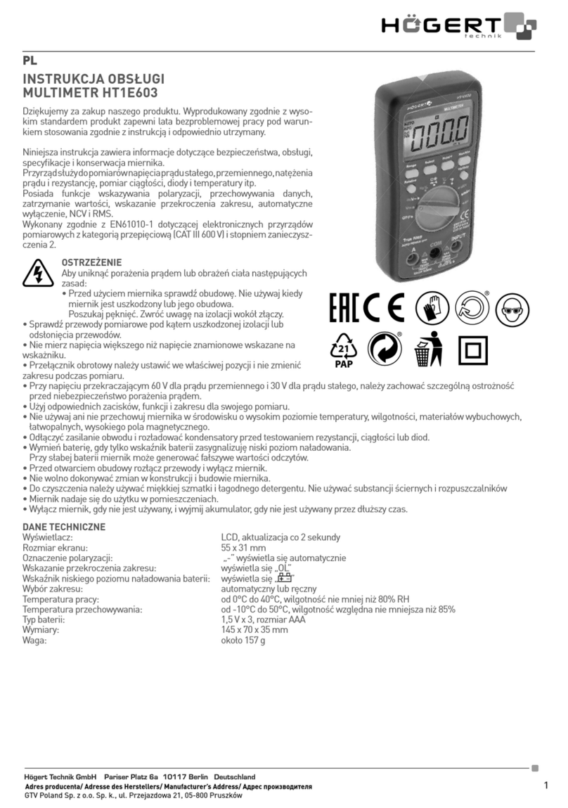
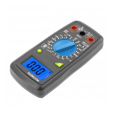
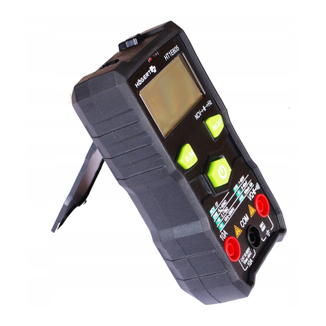
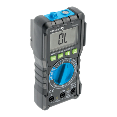
HOGERT HT1E600 User manual

1
Adres producenta/ Adresse des Herstellers/ Manufacturer’s Address/ Адрес производителя
GTV Poland Sp. z o.o. Sp. k., ul. Przejazdowa 21, 05-800 Pruszków
PL
INSTRUKCJA OBSŁUGI
MULTIMETR HT1E600
Dziękujemy za zakup naszego produktu. Wyprodukowany zgodnie z wysokim
standardem produkt zapewni lata bezproblemowej pracy pod warunkiem sto-
sowania zgodnie z instrukcją i odpowiednio utrzymany.
SPIS TREŚCI
1.Ogólne
2.Informacje dotyczące bezpieczeństwa
3.Opis i funkcje
3-1. Wygląd produktu opis
3-2. Przyciski funkcyjne
3-3. Wyświetlacz LCD
4.Dane techniczne
4-1. Funkcje ogólne
4–2. Wskaźniki dokładności
5.Pomiary
5-1. Pomiar napięcia prądu przemiennego i stałego
5–2. Pomiar rezystancji
5-3. Pomiar prądu przemiennego i stałego
5-4. Test diod
5-5. Test ciągłości
5-6. Pomiar częstotliwości
6. Konserwacja
6-1. Wymiana baterii
6-2. Wymiana bezpiecznika
6-3. Konserwacja
OCHRONA ŚRODOWISKA
Symbol wskazujący na selektywne zbieranie zużytego sprzętu elektrycznego i elektronicznego. Zużyte urządzenia elek-
tryczne są surowcami wtórnymi – nie wolno wyrzucać ich do pojemników na odpady domowe, ponieważ zawierają sub-
stancje niebezpieczne dla zdrowia ludzkiego i środowiska! Prosimy o aktywną pomoc w oszczędnym gospodarowaniu
zasobami naturalnymi i ochronie środowiska naturalnego przez przekazanie zużytego urządzenia do punktu składowania
zużytych urządzeń elektrycznych. Aby ograniczyć ilość usuwanych odpadów konieczne jest ich ponowne użycie, recykling
lub odzysk w innej formie.
1. INFORMACJE OGÓLNE
Urządzenie jest przeznaczone do użytku zarówno w prywatnych gospodarstwach domowych jak i do użytku komercyjnego. Multimetr
cyfrowy HT1E600 to innowacyjny, wydajny, niezawodny, w pełni funkcjonalny, z dużym ekranem instrument pomiarowy.
Miernik jest wyposażony w obwód zabezpieczający przed przeciążeniem i system natychmiastowego odłączenia, który może być uży-
wany do pomiaru napięcia stałego i przemiennego, prądu przemiennego i stałego, rezystancji, pojemności, częstotliwości, przewodów
pod napięciem, napięcia akumulatora, bezdotykowego wykrywania napięcia prądu zmiennego NCV, ciągłość diod i obwodów.
Wszelkie inne sposoby użytkowania nie są zamierzone i mogą prowadzić do uszkodzenia mienia lub nawet obrażeń ciała. Urządzenie
należy używać wyłącznie zgodnie z niniejszą instrukcją obsługi. Producent nie ponosi żadnej odpowiedzialności za uszkodzenia spo-
wodowane użytkowaniem niezgodnym z przeznaczeniem. Urządzenie nie jest przyrządem pomiarowym w rozumieniu ustawy “Prawo
o pomiarach”.
OGÓLNE WARUNKI BEZPIECZEŃSTWA
W zakresie właściciela i użytkownika jest przeczytanie, zrozumienie i przestrzeganie poniższych zasad:
WAŻNE: Proszę przeczytać tą instrukcję uważnie. proszę zwrócić szczególną uwagę na wymogi bezpiecznego użytkowania,
ostrzeżenia i uwagi. używać produkt prawidłowo i z uwagą do celów, do których został przeznaczony. nieprzestrzeganie tego
może spowodować uszkodzenie i/lub uszczerbek zdrowia i spowoduje utratę gwarancji. proszę przechowywać instrukcję w
bezpiecznym miejscu w celu dalszego używania. przekazując urządzenie innej osobie, oddaj jej także instrukcję obsługi.
• Proszę wykorzystywać urządzenie jedynie dla celu, jaki został przewidziany dla urządzenia.
• Proszę trzymać urządzenie z daleka od ciepła, bezpośredniego promieniowania słonecznego, wilgoci (w żadnym wypadku nie zanurzać
w substancjach płynnych) oraz ostrych krawędzi. Proszę nie obsługiwać urządzenia wilgotnymi dłońmi.
• Pracującego urządzenia nie należy pozostawiać bez nadzoru. Przed opuszczeniem pomieszczenia urządzenie należy zawsze wyłączyć.
• Należy regularnie sprawdzać, czy urządzenie nie jest uszkodzone. W razie wykrycia uszkodzenia należy przestać korzystać z urządzenia.
• Dla bezpieczeństwa dzieci proszę nie zostawiać swobodnie dostępnych części opakowania (torby plastikowe, kartony, styropian, itp.).
OSTRZEŻENIE
Nie pozwalaj dzieciom bawić się folią. Niebezpieczeństwo uduszenia!
To urządzenie nie jest przeznaczone do użytku przez osoby z ograniczonymi zdolnościami fizycznymi, sensorycznymi lub umysłowymi
lub brakiem doświadczenia i / lub umiejętności, chyba że takim osobom towarzyszą i są nadzorowane przez osoby odpowiedzialne
za ich bezpieczeństwo lub otrzymały precyzyjne instrukcje użytkowania tego urządzenia i zrozumiały wynikające z tego ryzyko. Dzieci
mogą korzystać z tego urządzenia tylko w wieku powyżej 8 i pod nadzorem osoby odpowiedzialnej za ich bezpieczeństwo lub jeśli
otrzymały instrukcje użytkowania tego urządzenia i zrozumiały wynikające z tego ryzyko. Dzieci nie mogą bawić się tym urządzeniem.

2Adres producenta/ Adresse des Herstellers/ Manufacturer’s Address/ Адрес производителя
GTV Poland Sp. z o.o. Sp. k., ul. Przejazdowa 21, 05-800 Pruszków
2. INFORMACJE DOTYCZĄCE BEZPIECZEŃSTWA
Multimetr cyfrowy HT1E600 został zaprojektowany zgodnie z dyrektywą IEC61010-1 600 V (CATIII) i poziomem zanieczyszczenia 2.
Aby zapewnić prawidłowe i bezpieczne użytkowanie miernika, należy uważnie przeczytać instrukcję obsługi.
• Nie mierzyć napięcia, które przekracza zakres pomiarowy określony dla tego miernika.
• Pomimo wewnętrznego obwodu ochronnego dla pola pomiaru rezystancji, NIE należy dodawać napięcia 100 V lub więcej do zacisku
wejściowego w polu pomiaru rezystancji.
• Sprawdź poprawność przyłączenia sond.
• Unikaj używania miernika w bezpośrednim świetle słonecznym lub ekstremalnie wysokich temperaturach, o ile to możliwe.
• Unikaj ryzyka porażenia prądem podczas pomiaru napięć przekraczających 30 V AC lub 60 C DC.
• Przed pomiarem prądu należy wyłączyć zasilacz i odłączyć go od obwodu przed pomiarem.
• Podczas wymiany baterii zwracaj uwagę na biegunowość.
SYMBOLE ELEKTRYCZNE:
Niebezpieczne napięcie Uziemienie
AC (prąd zmienny) Ostrzeżenie
DC (prąd stały) Podwójna izolacja
AC lub DC Bezpiecznik
3. OPIS I FUNKCJE
3-1. Opis produktu
1. NCV, pomiar ciągłości i przewodu pod napięciem
2. Wyświetlacz ciekłokrystaliczny (LCD)
3. „SEL / VFC” Wybór funkcji i przycisk pomiaru napięcia o zmiennej
częstotliwości
4. Przycisk przełączania zakresu „RANGE”
5. Przycisk przełączania częstotliwości „HZ / ”
i sterowania latarką
6. Przycisk „HOLD / ” zatrzymania danych
i sterowania podświetleniem
7. Pokrętło wyboru zakresu funkcji
8. „V/Ω/mA/μA/Cap/Battery/Live” gniazdo wejściowe
9. Zacisk wejściowy 10A
10. Zacisk wejściowy COM

3
Adres producenta/ Adresse des Herstellers/ Manufacturer’s Address/ Адрес производителя
GTV Poland Sp. z o.o. Sp. k., ul. Przejazdowa 21, 05-800 Pruszków
32. PRZYCISKI FUNKCYJNE
Przycisk Funkcja
SEL/V.F.C
Naciśnij przycisk „SEL”, aby przełączyć funkcję i jednostkę miary; przytrzymanie tego przycisku w polu napięcia
prądu przemiennego przez 2 sekundy spowoduje przejście miernika w tryb pomiaru VFC.
Gdy pokrętło znajduje się w pozycji OFF, przytrzymaj przycisk SEL i obracaj pokrętłem, aby włączyć miernik,
anuluje to funkcję automatycznego wyłączania.
RANGE
Naciśnij przycisk „RANGE”, aby wybrać zakres automatyczny/ręczny. Po każdym naciśnięciu aktywowany jest
wyższy zakres, ale po osiągnięciu najwyższego zakresu nastąpi powrót do najniższego zakresu, a następnie
cyklicznie w tej samej kolejności. Przytrzymanie tego przycisku przez 2 sekundy w ręcznym trybie zakresu po-
woduje powrót do trybu automatycznego zakresu.
HZ/
W polu napięcia prądu przemiennego lub prądu przemiennego naciśnij ten przycisk, aby wyświetlić zmierzone
napięcie lub częstotliwość prądu; Naciśnij ponownie, aby wyjść z wyświetlania częstotliwości. Przytrzymaj ten
przycisk przez około 2 sekundy, aby włączyć latarkę, która wyłącza się automatycznie po 15 sekundach; można
go wyłączyć, ponownie przytrzymując przycisk.
HOLD/
Aby zatrzymać odczyt podczas pomiaru, możesz nacisnąć przycisk „HOLD”, a następnie odczyt pomiaru zo-
stanie zablokowany na wyświetlaczu. Naciśnij ponownie przycisk „HOLD” , stan wstrzymania odczytu zostanie
zwolniony. Przytrzymaj ten przycisk przez około 2 sekundy, aby włączyć podświetlenie, które wyłącza się auto-
matycznie po 15 sekundach; można go wyłączyć, ponownie przytrzymując przycisk.
33. EKRAN LCD
Nr. Symbol Opis
1DC Prąd stały
2AC Prąd przemienny
3Dioda
4Ciągłość
5NCV Bezkontaktowy pomiar napięcia
prądu przemiennego
6V. F. C. Pomiar częstotliwości
7Test przewodu pod napięciem
8Automatyczne wyłączanie
9Bezpiecznik odłączony
10 HOLD Zapis danych
11 Niskie poziom naładowania baterii
12 MKΩ Jednostki oporności: Ω. KΩ, MΩ
13 nµmF Jednostki pojemności: nF, μF, mF
14 Auto Zakres automatyczny
15 Manual Zakres ręczny
16 µmVA Jednostki napięcia: MV, V
Jednostki natężenia: μA, mA, A
17 Symbol „negative”

4Adres producenta/ Adresse des Herstellers/ Manufacturer’s Address/ Адрес производителя
GTV Poland Sp. z o.o. Sp. k., ul. Przejazdowa 21, 05-800 Pruszków
4. DANE TECHNICZNE
4-1. Funkcje ogólne
• Automatyczny zakres.
• Wyświetlacz: 4-cyfrowy „9999, RMS.
• Funkcja alarmu odłączenia bezpiecznika
• Maksymalne napięcie do masy na zacisku wejściowym napięcia: 600 V CAT III
• Funkcja zatrzymywania danych
• Pomiar napięcia / częstotliwości prądu przemiennego
• Wskazanie przekroczenia zakresu: OL
• Wskazanie niskiego napięcia baterii:
• Czas automatycznego wyłączania: 15 minut
• Środowisko pracy: 0 ~ 40 ° C (32 ~ 104 ° F); <80% RH
• Warunki przechowywania: -10 ~ 50 ° C (14 ~ 122 ° F); <70% RH
• Zasilanie: 2 x 1.5V Bateria AAA
• Poziom bezpieczeństwa: IEC61010-1, CAT III 600 V
• Wymiary (150 x 70 x 50 mm) i waga: 195G
42. DOKŁADNOŚĆ WSKAZAŃ
Temperatura otoczenia: od 18 ° C do 28 ° C. Wilgotność środowiska: <80%.
4.2.1 Napięcie prądu stałego
Zakres Rozkład Dokładność
999,9mV 0,1 mV
± (0,7% odczytu + 3 cyfry)9,999 V 0,001 V
99,99 V 0,01 V
600 V 0,1 V ± (0,8% Odczyt + 2 cyfry)
- Zabezpieczenie przed przeciążeniem: PTC 600 V DC lub AC RMS.
4.2.2 Napięcie prądu przemiennego
Zakres Rozkład Dokładność
0,999 V. 0,001 V.
± (1% czytanie + 3 cyfry)9,999 V. 0,01 V.
99,99 V. 0,1 V.
600 V. 0,1 V. ± (1,2% odczytu + 3 cyfry)
* * Pokazuje TRUE RMS, gdy impedancja wejściowa wynosi około 10 MΩ; pasmo przenoszenia: 45 ~ 400 Hz
* * Maksymalne napięcie wejściowe: 600 V AC (wartość skuteczna)
4.2.3 Oporność
Zakres Rozkład Dokładność
999,9Ω 0,1 Ω
± (1% odczyt + 2 cyfry)
9,999 KΩ 0,001kΩ
99,99kΩ 0,01kΩ
999,9kΩ 0,1 kΩ
9,999 MΩ 0,001 MΩ
99,99MΩ 0,01 MΩ ± (2,0% odczytu + 3 cyfry)

5
Adres producenta/ Adresse des Herstellers/ Manufacturer’s Address/ Адрес производителя
GTV Poland Sp. z o.o. Sp. k., ul. Przejazdowa 21, 05-800 Pruszków
4.2.4
Zakres Funkcjonalność
LIVE Włóż tylko jedną sondę do zacisku wejściowego napięcia i użyj jej do przetestowania
gniazda zasilania w celu ustalenia przewodów neutralnych i pod napięciem.
4.2.5 Ciągłość diody i obwodu
Zakres Funkcjonalność
/
Test ciągłości i pomiar diod są wykonywane w trybie inteligentnym bez konieczno-
ści naciskania jakiegokolwiek przycisku przełączającego; gdy zmierzona rezystan-
cja jest mniejsza niż około 30 omów, wyświetla się wartość rezystancji włączonej,
wewnętrzny brzęczyk wydaje sygnał dźwiękowy, a wskaźnik ciągłości (zielony)
świeci; Podczas pomiaru diody wyświetla przybliżone napięcie przewodzące diody.
Napięcie w obwodzie otwartym wynosi około 3,3 V.
4.2.6 Natężenie prądu stałego
Zakres Rozkład Dokładność
999,9μA 0,1μA
± (0,8% Odczyt + 3 cyfry)
9999μA 1μA
99,99mA 0,01 mA
600 0,0 mA 0,1mA
10 A 0,01A ± (1,2% odczytu + 3 cyfry)
- Zabezpieczenie przed przeciążeniem: Zakres μA / mA: Bezpiecznik F600mA / 250V (szybkie wyłączenie bezpiecznika),
- Zakres 10 A: bezpiecznik F10A / 250 V (szybkie wyłączanie),
- Maksymalny prąd wejściowy: mA Gniazdo: 600 m, 10A
4.2.7 Natężenie prądu przemiennego
Zakres Rozkład Dokładność
999,9μA 0,1μA
± (1,0% Odczyt + 3 cyfry)
9999μA 1μA
99,99mA 0,01 mA
600 0,0 mA 0,1mA
10,00A 0,01A ± (1,5% odczytu + 3 cyfry)
- Zabezpieczenie przed przeciążeniem: zakres μA / mA: bezpiecznik F600mA / 250V (szybkie wyłączenie bezpiecznika),
- Zakres 10A: bezpiecznik F10A / 250 (szybkie wyłączanie),
- Maksymalny prąd wejściowy: mA: 600 mA , 10 A : 10 A.
- Pasmo przenoszenia: 45 ~ 400 Hz

6Adres producenta/ Adresse des Herstellers/ Manufacturer’s Address/ Адрес производителя
GTV Poland Sp. z o.o. Sp. k., ul. Przejazdowa 21, 05-800 Pruszków
4.2.8 Pojemność
Zakres Rozkład Dokładność
9,999nF 0,001 nF
± (4,0% Odczyt + 3 cyfry)
99,99nF 0,01 nF
999,9nF 0,1 nF
9,999µF 0,001 µF
99,99µF 0,01µF
999,9µF 0,1µF
9,999mF 0,001 mF
99,99mF 0,01 mF ± (5,0% Odczyt + 30 cyfr)
4.2.9 Bezkontaktowe wykrywanie napięcia przemiennego NCV
Zakres Opis
Niskie pole Wyświetlacz - L, wskaźnik NCV (zielony) świeci, a brzęczyk wydaje alarm
Wysokie pole Wyświetlacz - H, wskaźnik NCV (dwie czerwone diody LED) świeci,
podczas gdy brzęczyk wydaje alarm
4.2.10 Pomiar napięcia akumulatora
Zakres Opis
1,5 V Rezystancja obciążenia wynosi około 30 omów i pokazuje napięcie akumulatora
9 V Rezystancja obciążenia wynosi około 300 omów i pokazuje napięcie akumulatora
5. POMIARY
5-1. Pomiar napięcia prądu przemiennego i stałego
Nie należy mierzyć napięcia wyższego niż 600 V prądu stałego lub 600 V prądu przemiennego, aby uniknąć porażenia
prądem i / lub uszkodzenia miernika. Nie należy przykładać napięcia większego niż 600 V prądu stałego lub 600 V prądu
przemiennego między wspólny zacisk a uziemieniem, aby uniknąć porażenia prądem i / lub uszkodzenia miernika.
1. Ustaw pokrętło na ikonę .
2. Podłącz czarną sondę odpowiednio do gniazda wejściowego „COM”, a czerwoną do gniazda wejściowego „V”.
3. Domyślną pozycją w polu jest napięcie stałe. Naciśnij przycisk SEL, aby przełączyć na napięcie zmienne AC. W polu napięcia
AC przytrzymaj przycisk SEL / VFC przez około 2 sekundy, miernik przejdzie w tryb pomiaru napięcia o zmiennej częstotliwości,
który umożliwia stabilny pomiar. Naciśnij ponownie przycisk, aby wyjść z trybu VFC.
4. Użyj dwóch końcówek sondy, aby zmierzyć napięcie badanego obwodu. (Równolegle z badanym obwodem). Uzyskaj zmierzoną
wartość napięcia na wyświetlaczu. Podczas pomiaru napięcia prądu stałego wyświetlacz pokaże biegunowość napięcia, do
którego podłączona jest czerwona sonda. Podczas pomiaru napięcia prądu przemiennego naciśnij przycisk HZ, aby wyświetlić
na razie wartość częstotliwości napięcia.
Uwaga: W zakresie prądu stałego mV lub prądu przemiennego 9,999 V, nawet jeśli nie ma wejścia ani połączenia z sondami,
czasami miernik wyświetla kilka cyfr, co jest normalne. W takim przypadku przez zwarcie zacisków „V” i „COM” miernik
można zresetować do zera.
5-2. Pomiar rezystancji i pojemności
Aby uniknąć uszkodzenia miernika lub testowanego urządzenia, należy odłączyć zasilanie
testowanego obwodu i całkowicie rozładować wszystkie kondensatory wysokiego
napięcia przed pomiarem rezystancji.
Pomiar rezystancji:
1. Ustaw przełącznik obrotowy na pole „ ”. Na początku miernik wyświetla „OL”, wskazując, że wejście jest w obwodzie otwar-
tym, tzn. nie podłączono żadnej rezystancji.
2. Podłącz czarną sondę odpowiednio do gniazda wejściowego „COM”, a czerwoną do gniazda wejściowego „V”.
3. Użyj końcówek sondy, aby zmierzyć rezystancję badanego obwodu.
4. Odczytaj zmierzoną wartość rezystancji na wyświetlaczu.

7
Adres producenta/ Adresse des Herstellers/ Manufacturer’s Address/ Адрес производителя
GTV Poland Sp. z o.o. Sp. k., ul. Przejazdowa 21, 05-800 Pruszków
Pomiar pojemności:
1. Obrócić pole przełącznika obrotowego „ ”. Naciśnij klawisz SEL, aby przejść do trybu pomiaru pojemności.
2. Podłącz czarną sondę odpowiednio do gniazda wejściowego „COM”, a czerwoną do gniazda wejściowego „V”.
3. Użyj końcówek sondy, aby zmierzyć pojemność testowanego kondensatora.
4. Odczytaj zmierzoną wartość pojemności na wyświetlaczu.
Uwaga: Podczas pomiaru niskiej rezystancji, w celu dokładnego pomiaru, należy zewrzeć obie sondy, aby uzyskać wartość re-
zystancji zwarcia, a następnie należy ją odjąć od zmierzonej wartości rezystancji. Podczas pomiaru rezystancji w polu 99,99 M,
w niektórych przypadkach ustabilizowanie odczytu zajmie kilka sekund. Jest to normalne w przypadku pomiarów o wysokiej
rezystancji. W trybie pomiaru pojemnościowego po przekroczeniu maksymalnego zakresu wyświetli się „OL”. Podczas po-
miaru kondensatora o dużej pojemności mierzenie go zwykle trwa kilka sekund. Przed pomiarem kondensatora konieczne
jest zwolnienie ładunku resztkowego, co jest szczególnie ważne w przypadku kondensatora o wysokim napięciu, aby uniknąć
uszkodzenia miernika i zagrożeń osobistych.
5-3. Pomiar natężenia prądu przemiennego i stałego
Nie próbuj mierzyć prądu w obwodzie, gdy napięcie między napięciem w obwodzie otwartym a ziemią przekracza 250 V.
Przepalenie bezpiecznika podczas pomiaru może spowodować uszkodzenie miernika lub obrażenia ciała.
Gdy bezpiecznik jest odłączony, aby uniknąć uszkodzenia miernika lub sprzętu, należy wymienić bezpiecznik na taki sam
przed pomiarem. Do pomiaru użyj właściwego gniazda wejściowego i pola funkcyjnego. Gdy sonda jest podłączona do
gniazda wejściowego prądu, nie podłączaj końcówki sondy do żadnego obwodu w trybie równoległym.
1. Odłącz zasilanie badanego obwodu. Rozładuj wszystkie kondensatory wysokiego napięcia w badanym obwodzie.
2. Obróć przełącznik obrotowy na odpowiednie pole prądu. Użyj przycisku „SEL”, aby wybrać tryb pomiaru prądu stałego lub
przemiennego.
3. Włóż czarną sondę do gniazda wejściowego „COM”, a czerwoną sondę do odpowiedniego gniazda wejściowego prądu.
4. Odłącz testowany obwód. Podłącz czarną sondę do końca o niskim potencjale obwodu, który został odłączony, i podłącz czer-
woną sondę do końca o wysokim potencjale obwodu, który został odłączony. (Odwrócenie sond da ujemną wartość odczytu, ale
nie uszkodzi miernika.)
5. Włącz zasilanie testowanego obwodu, a następnie wyświetl wyświetlany odczyt. Jeśli wyświetlacz pokazuje tylko „OL”, oznacza
to, że sygnał wejściowy przekracza zakres.
6. Odciąć zasilanie badanego obwodu. Rozładuj wszystkie kondensatory wysokiego napięcia. Wyjmij sondy miernika i przywróć
obwód do pierwotnego stanu.
Uwaga: Podczas pomiaru dużego prądu 5–10 A czas włączenia nie powinien przekraczać 10 sekund, aby uniknąć niestabilnych
danych testowych z powodu ciepła. W przypadku wielokrotnego pomiaru odstęp między dwoma pomiarami powinien wynosić
3-5 minut.
5-4. Test ciągłości i diod
Aby uniknąć uszkodzenia miernika lub testowanego urządzenia, konieczne jest odłączenie zasilania testowanego
obwodu i rozładowanie wszystkich kondensatorów wysokiego napięcia przed pomiarem diod.
1. Ustaw przełącznik obrotowy na i podłącz końcówki sondy do obu końców mierzonego obiektu.
2. Podłącz czarną sondę odpowiednio do gniazda wejściowego „COM”, a czerwoną do gniazda wejściowego „V”.
3. Jeśli rezystancja mierzonego obiektu jest mniejsza niż 30 omów, miernik automatycznie przełączy się na pole Ciągłość. Zielony
wskaźnik wskaźnika wł. / Wył. Zaświeci się i rozlegnie się dźwięk brzęczyka, wskazując, że oba punkty są połączone, a wyświe-
tlacz LCD pokazuje wartość rezystancji.
4. Jeśli mierzonym obiektem jest dioda, miernik automatycznie przełączy się na pole diody, gdy jest w ciągłej przewodzie, a ekran
LCD wyświetla przybliżone napięcie przewodzące diody. Gdy dioda jest w obwodzie otwartym lub w odwrotnej polaryzacji, na
ekranie pojawi się „OL”. Normalna dioda w obwodzie powinna nadal wytwarzać spadek napięcia od 0,5 V do 0,8 V. jednak odczyt
odchylenia zwrotnego różni się od rezystancji innych kanałów między dwiema sondami.
5-5. Test przewodu pod napięciem
1. Ustaw przełącznik obrotowy w polu Live. Na ekranie wyświetla się „----”.
2. Podłącz czerwoną sondę tylko do gniazda wejściowego V.
3. Podłącz czerwoną końcówkę sondy do gniazda zasilania L lub w pobliżu przewodu pod napięciem, jeśli miernik wykryje napię-
cie prądu przemiennego, na ekranie pojawi się komunikat LIVE ; dwie czerwone diody po prawej górnej stronie panelu zaświecą
się, i włączy się brzęczyk, co oznacza że przewód jest pod napięciem.
5-6. Test NCV
Na działanie detekcji mogą mieć wpływ takie czynniki, jak konstrukcja gniazda, grubość i rodzaj izolacji. Nawet jeśli nie
jest wskazane jako LIVE, napięcie może nadal tam istnieć. Nie należy polegać wyłącznie na bezdotykowym detektorze
napięcia w celu ustalenia, czy na przewodzie występuje napięcie.
Kiedy napięcie wejściowe jest doprowadzane do zacisku wejściowego miernika, wskaźnik wykrywający napięcie może zapalić się
z powodu obecności napięcia indukowanego.
Ale źródła zakłóceń w otoczeniu zewnętrznym (takie jak latarki, silniki itp.) Mogą przypadkowo uruchomić bezdotykowe wykrywanie
napięcia.
1. Ustaw przełącznik zakresu funkcji w polu NCV. Aby określić obecność napięcia zmiennego lub pola elektromagnetycznego na
obiekcie, umieść sondę ze znakiem „NCV” na przedniej części miernika w pobliżu mierzonego obiektu.

8Adres producenta/ Adresse des Herstellers/ Manufacturer’s Address/ Адрес производителя
GTV Poland Sp. z o.o. Sp. k., ul. Przejazdowa 21, 05-800 Pruszków
2. Po wykryciu napięcia prądu przemiennego ekran, wskaźnik NCV i brzęczyk wskazują jednocześnie poziom napięcia.
Gdy indukowane napięcie jest niskie, na wyświetlaczu pojawia się „--L”. Zielona dioda po lewej stronie wskaźnika NCV świeci
się, a brzęczyk wydaje ciągły alarm.
3. Gdy indukowane napięcie jest wysokie, wyświetlacz pokazuje „--H”. Dwie czerwone diody LED po lewej stronie wskaźnika NCV
zapalają się, a brzęczyk emituje alarm w sposób ciągły z większą częstotliwością.
5-7. Pomiar baterii
Podłącz czarną sondę do gniazda COM, a czerwoną sondę do gniazda „V Ω mA”.
Ustaw przełącznik zakresu funkcji w polu pomiaru akumulatora 9 V lub 1,5 V zgodnie z mierzonym typem akumulatora, użyj
czerwonej sondy, aby dotknąć bieguna „+” mierzonego akumulatora, a czarnej sondy, aby dotknąć bieguna „-”, a następnie
odczytaj zmierzone napięcie akumulatora z ekranu LCD.
6. KONSERWACJA
6-1. Wymiana baterii
Jeśli symbol pojawia się na wyświetlaczu LCD podczas użytkowania miernika należy wymienić baterię,
aby zapobiec nieprawidłowemu odczytywaniu pomiarów.
1. Odłącz linie testowe. Wyłącz zasilanie.
2. Za pomocą śrubokręta otwórz pokrywę baterii z tyłu, a następnie wyjmij baterię.
3. Umieść naładowaną baterię i załóż pokrywę.
6-2. Wymiana bezpiecznika
1. Najpierw usuń linie testowe i wyłącz miernik.
2. Za pomocą śrubokręta otwórz tylną pokrywę, a następnie wyjmij zły bezpiecznik.
3. Włóż podobny bezpiecznik, przenieś tylną pokrywę i przymocuj ją za pomocą śrub.
6-3. Konserwacja
W razie potrzeby użyj miękkiej szmatki, aby zetrzeć powierzchnię miernika.
Nie należy używać rozpuszczalników organicznych ani materiałów ściernych,
które mogą powodować korozję lub rozpuszczanie obudowy.

9
Adres producenta/ Adresse des Herstellers/ Manufacturer’s Address/ Адрес производителя
GTV Poland Sp. z o.o. Sp. k., ul. Przejazdowa 21, 05-800 Pruszków
EN
USER’S MANUAL
MULTIMETER HT1E600
Thank you for purchasing our product. Manufactured to a high standard, this
product will, if used according to these instructions, and properly maintained,
give you years of trouble free performance.
TABLE OF CONTENTS
1.General
2.Safety information
3.Description and functions
3-1. Product appearance - description
3-2. Function keys
3-3. LCD display
4. Technical Data
4-1. General functions
4–2. Accuracy indicators
5.Measurements
5-1. Measurement of alternating and direct current voltage
5–2. Resistance measurement
5-3. AC and DC current measurement
5-4. Diode test
5-5. Continuity test
5-6. Frequency measurement
6. Maintenance
6-1. Battery replacement
6-2. Fuse replacement
6-3. Maintenance
ENVIRONMENTAL PROTECTION
Symbol indicating separate collection of electrical and electronic equipment waste. Used electrical appliances are secon-
dary raw materials - they must not be disposed of in household waste, as they contain substances hazardous to human
health and the environment! Please actively help us to manage natural resources and protect the environment by handing
over used equipment to the waste electrical equipment storage point. To reduce the amount of waste disposed of, it is
necessary to reuse, recycle or recover it in another form.
1. GENERAL INFORMATION
The device is intended for use both in private households and for commercial purposes. The HT1E600 digital multimeter is an innova-
tive, powerful, reliable, fully functional, large screen measuring instrument.
The meter is equipped with an overload protection circuit and an instantaneous disconnection system that can be used to measure DC
and AC voltage, AC and DC current, resistance, capacitance, frequency, live wires, battery voltage, non-contact NCV detection, diode
and circuit continuity.
Any other use is not intended and may lead to property damage or even personal injury. Use the device only in accordance with this
manual. The manufacturer does not assume any liability for damage caused by improper use. The device is not a measuring device
within the meaning of the „Measurement Law”.
GENERAL SAFETY CONDITIONS
It is within the scope of the owner and user’s responsibility to read, understand and follow these rules:
IMPORTANT: Please read this manual carefully. Please pay special attention to the requirements of safe use, warnings and
notices. Use the product correctly and carefully for the purposes for which it is intended. Failure to do so may result in damage
and/or harm to health and will void the warranty. Please keep this manual in a safe place for further use. When passing the
device on to another person, also give them the manual.
• Please use the device only for the purpose intended for the device.
• Please keep the device away from heat, direct sunlight, moisture (under no circumstances immerse in liquid substances) and sharp
edges. Do not operate the device with wet hands.
• Do not leave the device running unattended. Always switch off the unit before leaving the room.
• Check regularly that the device is not damaged. If damage is detected, stop using the device.
• For the safety of children, please do not leave any freely accessible parts of the packaging (plastic bags, cartons, polystyrene, etc.).
WARNING
Don’t let the kids play with the foil. Danger of suffocation!
This device is not intended for use by persons with reduced physical, sensory or mental capabilities or lack of experience and/or skills,
unless such persons are accompanied and supervised by persons responsible for their safety or have received precise instructions
for the device usage and understand the risks involved. Children may only use this device if they are over 8 years old and under the
supervision of a person responsible for their safety or if they have received instructions for use of this device and understand the risks
involved. Children cannot play with this device.

10 Adres producenta/ Adresse des Herstellers/ Manufacturer’s Address/ Адрес производителя
GTV Poland Sp. z o.o. Sp. k., ul. Przejazdowa 21, 05-800 Pruszków
2. SAFETY INFORMATION
The HT1E600 digital multimeter is designed according to the IEC61010-1 600 V (CATIII) directive and contamination level 2. To ensure
proper and safe use of the meter, read the manual carefully.
• Do not measure a voltage that exceeds the measuring range specified for this meter.
• Despite the internal protective circuit for the resistance measurement field, do NOT add 100 V or more to the input terminal in the
resistance measurement field.
• Check that the probes are connected correctly.
Avoid using the meter in direct sunlight or extremely high temperatures, if possible.
• Avoid the risk of electric shock when measuring voltages exceeding 30 V AC or 60 C DC.
• Switch off the power supply and disconnect it from the circuit before the current measurement.
• Pay attention to polarity when replacing batteries.
ELECTRICAL SYMBOLS:
Dangerous voltage Ground
AC (Alternating Current) Warning
DC (Direct Current) Double insulation
AC or DC Fuse
3. DESCRIPTION AND FUNCTIONS
3-1. Product description
1. NCV, continuity and live wire measurement
2. Liquid crystal display (LCD)
3. „SEL / VFC” Function selection and button for measuring variable
frequency voltage
4. “RANGE” range switch button
5. Frequency switching button „HZ / ”
and control the flashlight
6. The „HOLD / ” button - data retention and backlight control
7. Function range selection knob
8. „V/Ω/mA/μA/Cap/Battery/Live” input socket
9. input terminal 10A
10. COM input terminal

11
Adres producenta/ Adresse des Herstellers/ Manufacturer’s Address/ Адрес производителя
GTV Poland Sp. z o.o. Sp. k., ul. Przejazdowa 21, 05-800 Pruszków
32. FUNCTION KEYS
Button Function
SEL/V.F.C
Press the „SEL” button to switch the function and unit of measurement; holding this button in the AC voltage
field for 2 seconds will put the meter into VFC measurement mode.
When the dial is in the OFF position, hold down the SEL button and turn the dial to turn the meter on, this can-
cels the automatic shutdown function.
RANGE Press the „RANGE” button to select automatic/manual range. Each time a higher range is activated, but when
the highest range is reached, it will return to the lowest range and then cyclically in the same order. Holding this
button for 2 seconds in manual range mode returns to automatic range mode.
HZ/
In the AC voltage or AC frequency field, press this button to display the measured current voltage or frequency;
press again to exit the frequency display. Hold this button down for about 2 seconds to turn on the flashlight,
which turns off automatically after 15 seconds; you can turn it off by pressing the button again.
HOLD/
To stop the reading during the measurement, you can press the „HOLD” button, and then the measurement re-
ading will be locked on the display. Press the „HOLD” button again, the read pause status will be released. Hold
this button down for about 2 seconds to turn on the backlight, which turns off automatically after 15 seconds;
you can turn it off by pressing the button again.
33. LCD SCREEN
No. Symbol Description
1DC Direct current
2AC Alternating current
3Diode
4Continuity
5NCV Non-contact AC voltage measu-
rement
6V. F. C. Frequency measurement
7Testing the live wire
8Automatic shutdown
9Fuse disconnected
10 HOLD Recording of data
11 Low battery
12 MKΩ Resistance units: Ω. KΩ, MΩ
13 nµmF Capacity units: nF, μF, mF
14 Auto Automatic range
15 Manual Manual range
16 µmVA Voltage units: MV, V
Amperage units: μA, mA, A
17 Symbol „negative”

12 Adres producenta/ Adresse des Herstellers/ Manufacturer’s Address/ Адрес производителя
GTV Poland Sp. z o.o. Sp. k., ul. Przejazdowa 21, 05-800 Pruszków
4. TECHNICAL DATA
4-1. General functions
• Automatic range.
• Display: 4-digit 9999, RMS.
• Fuse disconnection alarm function
• Maximum voltage to ground at the voltage input terminal: 600 V CAT III
• Data retention function
• Measurement of AC voltage / frequency
• Indication of overrange: OL
• Display of low battery voltage:
• Automatic shutdown time: 15 minutes
• Working environment: 0 ~ 40 ° C (32 ~ 104 ° F); <80% RH
• Storage conditions: -10 ~ 50 ° C (14 ~ 122 ° F); <70% RH
• Power supply: 2 x 1.5V AAA battery
• Safety level: IEC61010-1, CAT III 600 V
• Dimensions (150 x 70 x 50 mm) and weight: 195G
42. ACCURACY OF INDICATIONS
Ambient temperature: 18°C to 28°C. Humidity of the environment: <80%.
4.2.1 Alternating current voltage
Range Layout Accuracy
999,9mV 0,1 mV
± (0.7% reading + 3 digits)9,999 V 0,001 V
99,99 V 0,01 V
600 V 0,1 V ± (0.8% reading + 2 digits)
- Overload protection: PTC 600 V DC or AC RMS.
4.2.2 Alternating current voltage
Range Layout Accuracy
0,999 V. 0,001 V.
± (1% reading + 3 digits)9,999 V. 0,01 V.
99,99 V. 0,1 V.
600 V. 0,1 V. ± (1.2% reading + 3 digits)
* * Shows TRUE RMS when input impedance is about 10 MΩ; bandwidth: 45 ~ 400 Hz
* * Maximum input voltage: 600 V AC (rms value)
4.2.3 Resistance
Range Layout Accuracy
999,9Ω 0,1 Ω
± (1% reading + 2 digits)
9,999 KΩ 0,001kΩ
99,99kΩ 0,01kΩ
999,9kΩ 0,1 kΩ
9,999 MΩ 0,001 MΩ
99,99MΩ 0,01 MΩ ± (2.0% reading + 3 digits)

13
Adres producenta/ Adresse des Herstellers/ Manufacturer’s Address/ Адрес производителя
GTV Poland Sp. z o.o. Sp. k., ul. Przejazdowa 21, 05-800 Pruszków
4.2.4
Range Functionality
LIVE Insert only one probe into the voltage input terminal and use it to test the power
outlet to determine neutral and live wires.
4.2.5 Diode and circuit continuity
Range Functionality
/
Continuity test and diode measurement are performed in intelligent mode without
pressing any switching button; when the measured resistance is less than about 30
ohms, the value of the resistance on is displayed, the internal buzzer beeps and the
continuity indicator (green) lights up; during the measurement, the diodes display
approximate conductive voltage of the diodes.
The voltage in an open circuit is about 3.3 V.
4.2.6 DC amperage
Range Layout Accuracy
999,9μA 0,1μA
± (0.8% reading + 3 digits)
9999μA 1μA
99,99mA 0,01 mA
600 0,0 mA 0,1mA
10 A 0,01A ± (1.2% reading + 3 digits)
- Overload protection: Range μA / mA: Fuse F600mA / 250V (quick fuse shutdown),
- Range 10 A: fuse F10A / 250 V (quick shutdown),
- Maximum input current: mA Socket: 600 m , 10A
4.2.7 Alternating current voltage
Range Layout Accuracy
999,9μA 0,1μA
± (1.0% reading + 3 digits)
9999μA 1μA
99,99mA 0,01 mA
600 0,0 mA 0,1mA
10,00A 0,01A ± (1.5% reading + 3 digits)
- Overload protection: μA / mA range: fuse F600mA / 250V (quick fuse shutdown),
- Range 10A: fuse F10A / 250 (quick shutdown),
- Maximum input current: mA: 600 m A , 10 A : 10 A.
- Band: 45 ~ 400 Hz

14 Adres producenta/ Adresse des Herstellers/ Manufacturer’s Address/ Адрес производителя
GTV Poland Sp. z o.o. Sp. k., ul. Przejazdowa 21, 05-800 Pruszków
4.2.8 Capacitance
Range Layout Accuracy
9,999nF 0,001 nF ± (4.0% reading + 30 digits)
99,99nF 0,01 nF
± (4.0% reading + 3 digits)
999,9nF 0,1 nF
9,999µF 0,001 µF
99,99µF 0,01µF
999,9µF 0,1µF
9,999mF 0,001 mF
99,99mF 0,01 mF ± (5.0% reading + 30 digits)
4.2.9 Non-contact detection of NCV AC voltage
Range Description
Low field Display - L, NCV indicator (green) lights up and buzzer issues an alarm
High field Display - H, NCV indicator (two red LEDs) lights up while the buzzer issues
an alarm
4.2.10 Battery voltage measurement
Reach Description
1.5 V The load resistance is about 30 ohms and shows the battery voltage
9 V The load resistance is about 300 ohms and shows the battery voltage
5. MEASUREMENTS
5-1. Measurement of AC and DC voltage
Do not measure a voltage higher than 600 V DC or 600 V AC to avoid electric shock and/or damage to the meter.
Do not apply a voltage higher than 600 V DC or
600 V AC between the common terminal and the earth to avoid electric shock and/or damage to the meter.
1. Set the dial to the icon .
2. Connect the black probe to the „COM” input socket and the red probe to the „V” input socket.
3. The default position in the field is DC voltage. Press the SEL button to switch to AC voltage. In the AC voltage field, hold down the
SEL / VFC button for about 2 seconds, the meter will switch to AC voltage measurement mode, which enables stable measure-
ment. Press the button again to exit VFC mode.
4. Use the two ends of the probe to measure the voltage of the tested circuit. (Parallel to the tested circuit). Get the measured
voltage value on the display. When measuring DC voltage, the display will show the polarity of the voltage to which the red probe
is connected. When measuring AC voltage, press the HZ button to display the voltage frequency value
Note: In the DC mV or AC 9.999 V range, even if there is no input or connection to the probes, sometimes the meter displays
several digits, which is normal. In this case, by shorting the terminals „V” and „COM” the meter can be reset to zero.
5-2. Resistance and capacitance measurement
To avoid damage to the meter or the device under test, disconnect the power supply to the circuit
under test and completely discharge all high voltage capacitors before measuring the resistance.
Resistance measurement:
1. Set the rotary switch to the field „ ”. At first the meter displays „OL”, indicating that the input is in an open circuit, i.e. no
resistance is connected.
2. Connect the black probe to the „COM” input socket and the red probe to the „V” input socket.
3. Use the probe tips to measure the resistance of the circuit being tested.
4. Read the measured resistance value on the display
Capacitance measurement:
1. Rotate rotary switch field „ ”. Press the SEL button to enter capacity measurement mode.
2. Connect the black probe to the „COM” input socket and the red probe to the „V” input socket.

15
Adres producenta/ Adresse des Herstellers/ Manufacturer’s Address/ Адрес производителя
GTV Poland Sp. z o.o. Sp. k., ul. Przejazdowa 21, 05-800 Pruszków
3. Use the probe tips to measure the capacity of the capacitor under test.
4. Read the measured capacity value on the display.
Note: During a low resistance measurement, both probes shall be short-circuited to obtain a short-circuit resistance value for
accurate measurement, and then subtracted from the measured resistance value.
When measuring the resistance in a 99.99 M field, in some cases it will take several seconds to stabilise the reading. This is
normal for measurements with high resistance.
In capacitive measurement mode, „OL” will be displayed when the maximum range is exceeded.
Measuring a large capacitor usually takes several seconds.
Before measuring the capacitor, it is necessary to release the residual charge, which is particularly important for a high volta-
ge capacitor to avoid damage to the meter and personal hazards.
5-3. AC and DC current measurement
Do not try to measure the current in a circuit when the voltage between the voltage in the open circuit and earth exceeds
250 V. Burning the fuse during measurement may cause damage to the meter or personal injury.
When the fuse is disconnected, to avoid damage to the meter or equipment, replace the fuse with the same one before
the measurement. Use the correct input socket and function field for measurement. When the probe is connected to a
current input socket, do not connect the probe tip to any circuit in parallel mode.
1. Disconnect the power supply to the tested circuit. Discharge all high voltage capacitors in the circuit being tested.
2. Turn the rotary switch to the appropriate current field. Use the SEL button to select the DC or AC measurement mode.
3. Insert the black probe into the „COM” input socket and the red probe into the corresponding power input socket.
4. Disconnect the circuit being tested. Connect the black probe to the low potential end of the circuit which has been disconnected
and connect the red probe to the high potential end of the circuit which has been disconnected. (Reversing the probes will give
a negative reading, but will not damage the meter.)
5. Turn on the power supply of the circuit being tested, and then the displayed reading. If the display only shows „OL”, it means that
the input signal is out of range.
6. Cut off the power to the circuit being tested. Discharge all high voltage capacitors. Remove the meter probes and restore the
circuit to its original state
Note: When measuring a large current of 5-10 A, the switch-on time should not exceed 10 seconds to avoid unstable test data
due to heat.
In case of multiple measurements, the interval between two measurements should be 3-5 minutes.
5-4. Continuity and diode test
To avoid damage to the meter or the equipment under test, it is necessary to disconnect the power supply to the circuit
under test and discharge all high voltage capacitors before measuring the diodes.
1. Set the rotary switch to and connect the probe ends to both ends of the measured object.
2. Connect the black probe to the „COM” input socket and the red probe to the „V” input socket.
3. If the resistance of the measured object is less than 30 ohms, the meter will automatically switch to the Continuity field. Green
indicator on/off light up and the buzzer sounds, indicating that both points are connected and the LCD shows the resistance
value.
4. If the measured object is a diode, the meter will automatically switch to the diode field when it is in a continuous wire and the
LCD screen displays the approximate voltage of the conductive diodes. When the diode is in an open circuit or in reverse polarity,
„OL” will appear on the screen. The normal diode in the circuit should still produce a voltage drop of 0.5 V to 0.8 V. However, the
readout of the return deviation is different from the resistance of other channels between the two probes.
5-5. Live wire test
1. Set the rotary switch in the Live field. The screen displays „----”.
2. Connect the red probe only to the V input socket.
3. Connect the red tip of the probe to the power supply socket L or near a live cable. If the meter detects AC voltage, the LIVE
message will appear on the screen; the two red diodes on the upper right side of the panel will light up, and a buzzer will sound,
indicating that the cable is live.
5-6. NCV test
Detection performance may be affected by factors such as the seat design, thickness and type of insulation. Even if it is
not indicated as LIVE, voltage may still be there. Do not rely solely on a non-contact voltage detector to determine
whether there is voltage on the wire.
When the input voltage is applied to the input terminal of the meter, the voltage detection indicator may light up due to the presen-
ce of induced voltage. But sources of interference in the external environment (such as flashlights, motors, etc.) can accidentally
trigger non-contact voltage detection.
1. Set the function range switch in the NCV field. To determine the presence of alternating voltage or electromagnetic field on an
object, place the probe with the „NCV” sign on the front of the meter near the object.
2. When AC voltage is detected, the screen, NCV indicator and buzzer simultaneously indicate the voltage level. When the induced
voltage is low, the display shows „--L”. The green diode on the left side of the NCV indicator lights up and the buzzer issues
a continuous alarm.
3. When the induced voltage is high, the display shows „--H”. The two red LED diodes on the left side of the NCV indicator light up
and the buzzer emits an alarm continuously at a higher frequency.

16 Adres producenta/ Adresse des Herstellers/ Manufacturer’s Address/ Адрес производителя
GTV Poland Sp. z o.o. Sp. k., ul. Przejazdowa 21, 05-800 Pruszków
5-7. Battery measurement
Connect the black probe to the COM socket, and the red probe to the socket „V mA”.
Set the function range switch in the 9 V battery measurement field or 1.5 V according to the type of measured battery, use the red
probe to touch the „+” pole of the measured battery and the black probe to touch the „-” pole, then read the measured battery
voltage from the LCD screen
6. MAINTENANCE
6-1. Battery replacement
If the symbol appears on the LCD display when the meter is used replace the battery to prevent incorrect readings.
1. Disconnect the test lines. Turn off the power.
2. Use a screwdriver to open the battery cover on the back, and then remove the battery.
3. Place a charged battery and put on the cover.
6-2. Fuse replacement
1. First remove the test lines and turn off the meter.
2. Use a screwdriver to open the rear cover, then remove the faulty fuse.
3. Insert a similar fuse, move the rear cover and fix it with screws.
6-3. Maintenance
If necessary, use a soft cloth to wipe the surface of the meter.
Do not use organic solvents or abrasive materials, which may cause corrosion or dissolution of the housing.

17
Adres producenta/ Adresse des Herstellers/ Manufacturer’s Address/ Адрес производителя
GTV Poland Sp. z o.o. Sp. k., ul. Przejazdowa 21, 05-800 Pruszków
DE
BENUTZERHANDBUCH
MULTIMETER HT1E600
Vielen Dank, dass Sie sich für unser Produkt entschieden haben.
Hergestellt nach hohen Standard, wird dieses Produkt, wenn den Anweisun-
gen entsprechend verwendet, und ordnungsgemäß gewartet, Ihnen störun-
gsfreien Betrieb garantieren.
INHALTSVERZEICHNIS
1.Allgemein
2.Sicherheitsinformationen
3.Beschreibung und Funktionen
3-1. Aussehen des Produkts Beschreibung
3-2. Funktionstasten
3-3. LCD-Anzeige
4.Technische Daten
4-1. Allgemeine Funktionen
4-2. Genauigkeitskennzahlen
5.Messungen
5-1. Messung von Wechselspannung und Gleichspannung
5-2. Widerstandsmessung
5-3. Messung von Wechselstrom und Gleichstrom
5-4. Diodentest
5-5. Kontinuitätstest
5-6. Frequenzmessung
6. Pflege
6-1. Batteriewechsel
6-2. Austausch der Sicherung
6-3. Pflege
UMWELTSCHUTZ
Symbol das auf die gesonderte Sammlung von elektrischen und elektronischen Altgeräten hinweist. Elektrische Altgeräte
sind sekundäre Rohstoffe - sie dürfen nicht in die Behälter für Haushaltsabfälle geworfen werden, da sie die menschliche
Gesundheit und die Umwelt gefährdende Stoffe enthalten! Wir bitten um Ihren aktiven Beitrag zur sparsamen Bewirt-
schaftung der natürlichen Ressourcen und zum Umweltschutz, durch die Abgabe des Altgeräts bei der Sammelstelle für
elektrische Altgeräte. Um die Menge an entsorgten Abfällen zu reduzieren, ist deren Wiederverwendung, Recycling oder
Rückgewinnung in einer sonstigen Form notwendig.
1. ALLGEMEINE INFORMATIONEN
Das Gerät ist sowohl für den Einsatz in Privathaushalten als auch für den kommerziellen Gebrauch bestimmt. Das Digitalmultimeter
HT1E600 ist ein innovatives, leistungsstarkes, zuverlässiges und voll funktionales Messinstrument mit großer Anzeige.
Das Messgerät ist mit einem Stromkreis zum Schutz vor Überlastung und einem System zum sofortigen Abschalten ausgestattet, das
zur Messung von Gleich- und Wechselspannung, Wechsel- und Gleichstrom, Widerstand, Kapazität, Frequenz, Leiter unter Spannung,
Akku-Spannung, kontaktlose Erkennung von Wechselspannung NCV, Kontinuität von Dioden und Stromkreisen.
Jegliche davon abweichende Nutzung ist nicht zweckmäßig und kann zu Sachschäden oder sogar Körperverletzung führen. Das Gerät
ist ausschließlich im Einklang mit der vorliegenden Bedienungsanleitung zu nutzen. Der Hersteller haftet nicht für Schäden, die durch
eine unsachgemäße Verwendung entstehen. Das Gerät ist kein Messgerät im Sinne des Gesetzes „Messrecht“.
ALLGEMEINE SICHERHEITSBEDINGUNGEN
Beim Besitzer und Benutzer liegt die Pflicht, die nachstehenden Regeln zu lesen, zu verstehen und einzuhalten:
WICHTIG: Bitte lesen Sie die vorliegende Anleitung aufmerksam durch, achten Sie dabei besonders auf die Sicherheitsanfor-
derungen für den Gebrauch, Warnungen und Hinweise. Verwenden Sie das Produkt korrekt und unter Beachtung seines Ver-
wendungszwecks. Die fehlende Einhaltung des Obigen kann zu Sach- oder Gesundheitsschäden führen, und verursacht den
Verlust der Garantie. Bewahren Sie die Bedienungsanleitung bitte an einem sicheren Ort für die weitere Verwendung auf. Bei
der Übergabe des Geräts an eine andere Person sollten Sie dieser auch die Bedienungsanleitung übergeben.
• Verwenden Sie das Gerät bitte ausschließlich zu dem Zweck, zu dem es ausgelegt wurde.
• Halten Sie das Gerät fern von Wärmequellen, direkter Sonneneinstrahlung, Feuchtigkeit (keinesfalls in flüssige Stoffe eintauchen) so-
wie von scharfen Kanten. Gerät nicht mit feuchten Händen bedienen.
• Eingeschaltetes Gerät nicht unbeaufsichtigt lassen. Vor dem Verlassen des Raums ist das Gerät immer auszuschalten.
• Überprüfen Sie regelmäßig, ob das Gerät nicht beschädigt ist. Im Fall einer Beschädigung ist die Nutzung des Geräts zu unterbrechen.
• Im Hinblick auf die Sicherheit von Kindern sollten keine Verpackungsteile (Plastikbeutel, Kartons, Styropor etc.) frei zugänglich liegen
gelassen werden.
ACHTUNG
Kinder nicht mit der Folie spielen lassen. Erstickungsgefahr!
Dieses Gerät ist nicht für den Gebrauch durch Personen mit eingeschränkten physischen, sensorischen oder geistigen Fähigkeiten
oder mangelnder Erfahrung und/oder Fertigkeiten bestimmt, es sei denn, sie werden dabei von Personen begleitet und beaufsichtigt,
die für ihre Sicherheit verantwortlich sind, oder eine präzise Gebrauchsanleitung dieses Geräts erhalten und das daraus folgende Risi-

18 Adres producenta/ Adresse des Herstellers/ Manufacturer’s Address/ Адрес производителя
GTV Poland Sp. z o.o. Sp. k., ul. Przejazdowa 21, 05-800 Pruszków
ko verstanden haben. Nur Kinder über 8 Jahre dürfen das Gerät ausschließlich unter Aufsicht der für ihre Sicherheit verantwortlichen
Person verwenden, oder dann, wenn sie eine präzise Gebrauchsanleitung dieses Geräts erhalten und das daraus folgende Risiko
verstanden haben. Kinder dürfen nicht mit dem Gerät spielen
2. SICHERHEITSINFORMATIONEN
Das Digital-Multimeter HT1E600 wurde gemäß der Richtlinie IEC61010-1 600 V (CATIII) und dem Verunreinigungsgrad 2 entworfen.
Um die richtige und sichere Verwendung des Messgeräts zu gewährleisten, lesen Sie aufmerksam die Bedienungsanleitung.
• Keine Spannung messen, die den für dieses Messgerät festgelegten Messbereich überschreitet.
• Trotz des internen Schutzkreises für das Feld der Widerstandsmessung, darf KEINE Spannung von 100 V oder mehr an der Ein-
gangsklemme im Feld der Widerstandsmessung zugeführt werden.
• Überprüfen Sie den richtigen Sondenanschluss.
Vermeiden Sie die Verwendung des Messgeräts in direktem Sonnenlicht oder bei extrem hohen Temperaturen, sofern möglich.
• Vermeiden Sie das Risiko eines Stromschlags während der Messung von Spannungen, die 30 V AC oder 60 C DC überschreiten.
• Schalten Sie vor der Strommessung das Netzteil aus und trennen Sie es vor der Messung vom Stromkreis.
• Achten Sie während des Batteriewechsels auf die Polarität.
ELEKTRISCHE SYMBOLE:
Gefährliche Spannung Erdung
AC (Wechselstrom) Warnung
DC (Gleichstrom) Doppelte Isolierung
AC oder DC Sicherung
3. BESCHREIBUNG UND FUNKTIONEN
3-1. Produktbeschreibung
1. NCV, Kontinuitätsmessung und Messung eines unter Spannung ste-
henden Leiters
2. Flüssigkristallanzeige (LCD)
3. „SEL / VFC” Auswahl der Funktionen und Taste zur Messung von
Spannung mit veränderlicher Frequenz
4. Bereich-Umschalttaste „RANGE”
5. Frequenz-Umschalttaste „HZ / ” und Taschenlampen-Steuerung
6. „HOLD / ” Taste zum Halten von Daten und Steuerung
der Hintergrundbeleuchtung
7. Drehregler zur Auswahl des Funktionsbereichs
8. „V/Ω/mA/μA/Cap/Battery/Live” Eingangsbuchse
9. Eingangsklemme 10A
10. COM Eingangsklemme

19
Adres producenta/ Adresse des Herstellers/ Manufacturer’s Address/ Адрес производителя
GTV Poland Sp. z o.o. Sp. k., ul. Przejazdowa 21, 05-800 Pruszków
32. FUNKTIONSTASTEN
Taste Aufgabe
SEL/V.F.C
Drücken Sie die Taste „SEL”, um die Funktion und Maßeinheit umzuschalten; das Gedrückthalten dieser Taste
im Feld der Wechselspannung für mehr als 2 Sekunden führt zum Wechsel des Messgeräts in den VFC-Mes-
smodus. Wenn der Drehregler sich in der OFF-Position befindet, halten Sie die SEL-Taste gedrückt, um das
Messgerät einzuschalten, und die Funktion des automatischen Abschaltens abzubrechen.
RANGE
Drücken Sie die Taste „SEL”, um die Funktion und Maßeinheit umzuschalten; das Gedrückthalten dieser Taste
im Feld der Wechselspannung für mehr als 2 Sekunden führt zum Wechsel des Messgeräts in den VFC-Mes-
smodus. Wenn der Drehregler sich in der OFF-Position befindet, halten Sie die SEL-Taste gedrückt, um das
Messgerät einzuschalten, und die Funktion des automatischen Abschaltens abzubrechen.
HZ/
Im Feld der Wechselspannung oder des Wechselstroms diese Taste drücken, um die gemessene Spannung
oder Stromfrequenz anzuzeigen; Erneut drücken, um die Anzeige der Frequenz zu verlassen. Diese Taste etwa
2 Sekunden lang gedrückt halten, um die Taschenlampe einzuschalten, die automatisch nach 15 Sekunden
ausgeschaltet wird; sie kann durch Gedrückthalten der Taste erneut eingeschaltet werden.
HOLD/
Um die Anzeige während der Messung zu halten, können Sie die Taste „HOLD“ drücken und danach wird die
Anzeige der Messung auf dem Display gesperrt. Drücken Sie erneut die Taste „HOLD“, und der Halte-Zustand
der Anzeige wird freigegeben. Diese Taste etwa 2 Sekunden lang gedrückt halten, um die Hintergrundbeleuch-
tung einzuschalten, die automatisch nach 15 Sekunden ausgeschaltet wird; sie kann durch Gedrückthalten der
Taste erneut eingeschaltet werden.
33. LCDDISPLAY
Nr. Symbol Beschreibung
1DC Gleichstrom
2AC Wechselstrom
3Diode
4Kontinuität
5NCV Kontaktlose Wechselspannungs-
messung
6V. F. C. Frequenzmessung
7Leiter unter Spannung - Test
8Automatisches Abschalten
9Sicherung getrennt
10 HOLD Datenspeicherung
11 Niedriger Batterieladestand
12 MKΩ Widerstandseinheiten: Ω. KΩ, MΩ
13 nµmF Kapazitätseinheiten: nF, μF, mF
14 Auto Automatischer Bereich
15 Manual Manueller Bereich
16 µmVA Spannungseinheiten: MV, V
Stromstärkeeinheiten: μA, mA, A
17 Symbol „negative”

20 Adres producenta/ Adresse des Herstellers/ Manufacturer’s Address/ Адрес производителя
GTV Poland Sp. z o.o. Sp. k., ul. Przejazdowa 21, 05-800 Pruszków
4. TECHNISCHE DATEN
4-1. Allgemeine Funktionen
• Automatischer Bereich
• Anzeige: 4-stellig „9999, RMS.
• Alarm-Funktion bei getrennter Sicherung
• Maximale Spannung zur Masse an der Eingangsklemme der Spannung: 600 V CAT III
• Daten-Haltefunktion
• Kontaktlose Wechselspannungsmessung
• Anzeige der Bereichsüberschreitung: OL
• Anzeige von niedrigem Batteriestand:
• Automatische Abschaltzeit: 15 Minuten
• Arbeitsumfeld: 0 ~ 40 ° C (32 ~ 104 ° F); <80% RH
• Lagerbedingungen: -10 ~ 50 ° C (14 ~ 122 ° F); <70% RH
• Stromversorgung: 2 x 1.5V Batterie AAA
• Sicherheitsniveau: IEC61010-1, CAT III 600 V
• Abmessungen (150 x 70 x 50 mm) und Gewicht: 195G
42. GENAUIGKEIT DER ANZEIGEN
Umgebungstemperatur: zwischen 18°C und 28°C. Umgebungsfeuchte: <80%.
4.2.1 Gleichstromspannung
Bereich Verteilung Genauigkeit
999,9mV 0,1 mV
± (0.7 % Anzeige + 3 Stellen)9,999 V 0,001 V
99,99 V 0,01 V
600 V 0,1 V ± (0.8% Anzeige + 2 Stellen)
- Überlastungsschutz: PTC 600 V DC oder AC RMS.
4.2.2 Wechselstromspannung
Bereich Verteilung Genauigkeit
0,999 V. 0,001 V.
± (1 % Anzeige + 3 Stellen)9,999 V. 0,01 V.
99,99 V. 0,1 V.
600 V. 0,1 V. ± (1.2 % Anzeige + 3 Stellen)
** Zeigt TRUE RMS, wenn die Eingangsimpedanz etwa 10 MΩ beträgt; Übertragungsband: 45 ~ 400 Hz
** Zulässige Eingangsspannung: 600 V AC (effekiver Wert
4.2.3 Widerstand
Bereich Verteilung Genauigkeit
999,9Ω 0,1 Ω
± (1% Anzeige + 2 Stellen)
9,999 KΩ 0,001kΩ
99,99kΩ 0,01kΩ
999,9kΩ 0,1 kΩ
9,999 MΩ 0,001 MΩ
99,99MΩ 0,01 MΩ ± (2.0 % Anzeige + 3 Stellen)
Table of contents
Languages:
Other HOGERT Multimeter manuals

HOGERT
HOGERT HT1E605 User manual

HOGERT
HOGERT HT1E620 User manual

HOGERT
HOGERT HT1E621 User manual

HOGERT
HOGERT HT1E615 AUTO-SMART User manual

HOGERT
HOGERT HT1E601 User manual

HOGERT
HOGERT HT1E630 User manual

HOGERT
HOGERT HT1E603 User manual

HOGERT
HOGERT HT1E604 User manual

HOGERT
HOGERT HT1E602 User manual

HOGERT
HOGERT HT1E606 User manual