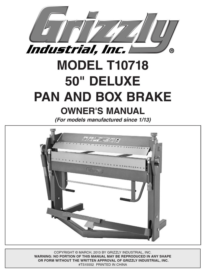
CLAUSING 1300 Series Technical reference manual

•>:
$
•s
INSTRUCTIONS
and
PARTS
MANUAL
Hi
§
Mmsmm
:•}
1
i
i
m
1300-series
LATHE
•.y":
&
1
m
p
P',:,
P
P
1301
P
;
v
*
p
CLAUSING
»
1
%
CORPORATION
2019
N.
PITCHER
ST.
KALAMA OO,
MICH.
49007
II*
P
■HHi
i
.
ll
......
M
..
I
\
p
p
»

r'?&.
m
IMPORTANT
—
your
clausing
warranty
is
NOT
effective
unless
this
card
is
returned
—
1
THIS
IS
YOUR
PERMANENT
RECORD
Your
Warranty
^
1
MODEL
NO:
MACHINE
SERIAL
NO:
NAME
OF
PURCHASER
STREET
CITY,
ZONE.
STATE
PURCHASED
FROM
DATE
PURCHASED
1
CLAUSING
CORPORATION
Service
Center
GOSHEN,
INDIANA
46526
2306
EISENHOWER
DRIVE
PHONE:
Area
Code
219
533-0371
TELEX:
258439
i
*
PRINTED
IN
U.S.A.
;

p
p
WARRANTY
p
p
i
The
Clausing
Corporation,
Kalamazoo,
Michigan,
warrants
that
each
Prod
uct
will
be
free
from
defects
in
material
and
workmanship
for
one
year
from
the
date
of
delivery
to
the
User.
]
i
Clausing
will
correct
any
defects
without
charge.
Parts
will
be
repaired
or
replaced
at
Clausing
’
s
option.
Warranty
work
will
normally
be
performed
at
the
User
’
s
plant,
but
at
the
option
and
expense
of
Clausing,
the
Product,
or
any
part
thereof,
may
be
returned
to
Clausing
for
the
service.
User
shall
provide
access
to
the
Product
during
regular
business
hours
and
shall
provide
such
other
assist
ance
as
determined
necessary
by
Clausing.
!
1
3
2
J
Clausing
shall
not
be
responsible
for
expenditures
made
or
incurred
by
the
User
for
repairs
of
the
Product.
The
warranty
is
void
for
any
Product
that
has
been
subjected
to
neglect,
misuse,
accident,
or
improper
operation,
or
that
has
been
tampered
with
or
altered
in
any
way.
1
-j
j
J.
I
The
foregoing
warranty
is
exclusive
and
in
lieu
of
all
other
warranties,
ex
press
or
implied,
except
as
to
title,
including
any
implied
warranty
of
MER
CHANTABILITY
or
of
FITNESS
FOR
A
PARTICULAR
PURPOSE.
I
•-
3
I
3
3
The
liability
of
Clausing
under
this
warranty,
or
for
any
loss
or
damage
to
the
equipment,
whether
the
claim
is
based
on
contract
or
negligence,
shall
not
in
any
case
exceed
the
cost
of
correcting
defects
in
the
equipment
as
herein
pro
vided
and
upon
the
expiration
of
the
warranty
period
all
such
liability
shall
termi
nate.
The
foregoing
shall
constitute
the
exclusive
remedy
of
the
User
and
the
exclusive
liability
of
Clausing.
■f
i
•
i-
s
i
~3
i
I
:i:
I
In
no
event,
whether
as
a
result
of
breach
of
contract
or
warranty,
or
alleged
negligence,
shall
Clausing
be
liable
for
special
or
consequential
damages
includ
ing,
but
not
limited
to,
loss
of
profits
or
revenue,
loss
of
use
of
the
equipment
or
any
associated
equipment,
cost
of
capital,
cost
of
substitute
equipment,
facilities
or
services,
down-time
costs,
or
claims
of
customers
of
the
User
for
such
damages.
I
i
It
*
H
No
one
other
than
an
officer
of
Clausing
acting
in
writing
is
authorized
to
assume
any
liability
on
behalf
of
Clausing
or
impose
any
obligation
upon
it
in
con
nection
with
the
sale
of
any
product
other
than
as
stated
above.
s
5
IP
CLAUSING
CORPORATION
KALAMAZOO,
MICHIGAN
49007
0
t-4
l
c-3
I
L

i
OCTOBER,
1975
THIS
MANUAL
APPLIES
TO
CLAUSING
1300
SERIES
LATHES
FROM
SERIAL
No.
131523
TO
FILE
No.
1300-3
9
1300
SERIES
LATHE
TABLE
OF
CONTENTS
i
INSTALLATION
General
Dimensions
..
Functional
Diagram
.
.
Foundation
.................
Uncrating
.....................
Cleaning
.......................
Lifting
...........................
Anchoring
...................
Leveling
.......................
Electrical
Connections
Wiring
Diagram
..........
1
2
3
3
3
3
3
3
&
4
4
9
5
LUBRICATION
Lubrication
Diagram
Lubrication
Chart
..
Approved
Lubricants
6
7
7
CONTROLS
AND
OPERATION
Headstock
Controls
.......................
Clutch
and
Brake
Controls
..........
Gear
Box
Controls
.........................
Lead
Screw
Control
.......................
Carriage
Controls
...........................
Power
Feed
Lever
...........................
Half
Nut
Lever
.................................
Thread
Dial
.....................................
Tailstock
..........................................
Mounting
Chucks
and
Face
Plates
8
9
9
j
9
9
10
10
j
10
10
11
MAINTENANCE
AND
ADJUSTMENTS
Clutch
Adjustment
.......................................
Clutch
Linkage
Adjustment
.......................
Clutch
Lever
Adjustment
...........................
Shear
Pin
Replacement
.............................
Lead
Screw
End
Play
Adjustment
............
Tailstock
Handwheel
Bearing
Adjustment
Checking
Center
Alignment
.....................
Adjusting
Tailstock
Alignment
................
Gib
Adjustments
..........................................
Handwheel
Thrust
Bearing
Adjustment
..
Cross
Slide
Nut
Adjustment
.....................
Timing
Belt
Replacement
.........................
Timing
Belt
Tension
Adjustment
............
Variable
Drive
Belt
Replacement
............
Variable
Speed
Belt
Adjustment
...............
12
12
12
12
13
13
13
13
14
14
14
15
15
15
16
I
1300

GENERAL
DIMENSIONS
-
1300
SERIES
CLAUSING
LATHE
O
O
60"
50"
BED
33-1/2"
72" 62"
BED
24"
50"
BED
36" 62"
BED
4\
J
n
tK
£
2
©
o
[8
O
u
^
i
•
FOR
REV
T
o
a
o
.
0
@
lull/iiiwiiiiiiiiiiiiiiiiiiiiiiiiiiiiiiiiiiiiiiiiiiiiitiitiiiiiiiiiiiiiniiiiiniiiiiiiiiiii
jf
1
■
o
48-1/2"
©LAPSON®
TJ
43-3/4"
I
5E.
c:
p
di
di
d5
di
di
db
■12-3/8"
—
►
24"
7"
-►
20-1/8"
5-1/2"
47-1/2
59-1/2
50"
BED
CLEARANCE
TO
REMOVE
MOTOR
62"
BED
NOTE:
DIMENSIONS
ARE
APPROXIMATE

------
r
TOOL
POST
SLIDE
HANDWHEEL
MOTOR
CONTROL
SPINDLE
TOOL
\
\
HOLDER
HALF
NUT
LEVER
RAM
•»
SPEED
RANGE
SELECTOR
RAM
LOCK
THREAD
DIAL
BED
CLAMP
RAM
HANDWHEEL
\
9
VARIABLE
SPEED
CONTROL
a
.0
LOCK
STUD
:
0
;
SLIDING
GEAR
LEVER
0
(•]
©
SET-OVER
SCREW
gear
selector
t
c
c
a
©o
THREAD/FEED
SELECTOR
LEVER
0
s>
0
CLUTCH
KICK-OUT
LEAD
SCREW
DIRECTION
CONTROL
ro
CROSS
FEED
HANDWHEEL
END
»
GUARD
LEAD
SCREW
CLUTCH
AND
BRA E
LEVER
0
POWER
FEED
LEVER
LEVELING
SCREW
o
CLUTCH
CONTROL
BAR
0
INNER
SUPPORT
SCREWS
e
LEVELING
SCREW
CO
o
c
i

INSTALLATION
FOUNDATION
The
Clausing
lathe
is
a
precision
machine
tool
re
quiring
a
firm
foundation.
The
floor
must
be
level
and
sol
id
enough
to
support
the
weight
of
the
machine
without
noticeable
deflection.
Reinforced
concrete
is
recommended;
it
provides
a
rigid
base,
minimizes
vibration
from
adjacent
machines
and
resists
deflec
tion.
bed,
see
figure
1.
Place
blocking
under
approximate
center
of
load,
rig
sling
as
shown.
Raise
lathe
about
one
inch
off
floor,
make
any
necessary
adjustment
for
balance
by
moving
carriage
along
bed.
Wood
floors
should
be
carefully
checked
for
strength.
Place
a
precision
level
on
floor
where
lathe
is
to
be
located,
and
move
a
hand
truck
with
average
load
past
it.
If
bubble
in
level
shows
noticeable
move
ment,
the
floor
should
be
reinforced,
or
cut
away
and
a
concrete
foundation
installed.
FIGURE
;
*
If
a
fork
lift
is
used,
remove
chip
pan,
place
2
”
thick
wood
blocking
under
bed
so
clutch
rod
will
not
be
bent
when
lathe
is
raised.
UNCRATING
Remove
crating
carefully.
For
ease
in
handling
do
not
remove
lathe
from
skid
until
the
lathe
has
been
moved
to
its
approximate
location.
w
ANCHORING
The
Clausing
lathe
is
equipped
with
eight
mounting
pads
which
eliminate
the
need
for
anchoring
the
lathe
to
floor.
If
anchoring
is
desired,
procede
as
follows:
.
Use
anchor
bolts
to
secure
lathe
to
concrete
floor-
use
lag
screws
to
secure
lathe
to
wood
floor
—
refer
to
figure
3.
With
a
hoist
or
lift,
lower
the
lathe
into
position
and
mark
the
eight
mounting
pad
locations.
CLEANING
CAUTION:
DO
NOT
MOVE
CARRIAGE
OR
TAIL-
STOCK
UNTIL
BED
WAYS
HAVE
BEEN
THOROUGHLY
CLEANED
AND
OILED
Use
a
clean
solvent
to
remove
rust
proof
coating
applied
to
unpainted
surfaces.
Exposed
bearing
sur
faces
should
be
cleaned
using
a
soft
cloth.
Use
a
stiff
bristle
brush
to
clean
the
lead
screw
and
rack.
Do
not
use
air
hose.
It
can
force
dirt
and
grit
into
bearings
and
slides.
When
thoroughly
cleaned,
cover
unpainted
surfaces
with
a
light
coating
of
medium
way
oil
(see
lubrication
chart).
w
ii
.ii
.
u<o
w
f
I
l
T
l
7
12
/**"
7
7-/
‘
/y
f
T
.
Li.flX
1
y
Lift
lathe
out
of
the
way,
drill
holes
for
anchor
nuts
and
install
anchor
nuts
-
for
lag
screws
drill
pilot
holes.
f
.
.
\nl\ly
lb'
—
•//
FIGURE
3
\
4
:
I
12*
Position
and
lower
lathe.
Turn
leveling
screws
until
no
portion
of
the
lathe
cabinet
touches
the
floor
-
shim
under
pads,
if
necessary.
1
m
m
im
M:
=5
-
1
iT-il
—
1
LEAD
SCREW
__L
3
essi
i
7
]
Start
anchor
bolts
or
lag
screws
—
DO
NOT
tighten
until
lathe
is
leveled
—
see
Leveling
instructions.
-WL
CLUTCH
ROD
4*.
4*«
30*
m
FIGURE
1
LEVELING
The
lathe
should
be
kept
perfectly
level
at
all
times.
When
carelessly
leveled,
the
bed
may
become
twist
ed.
Even
a
slight
amount
of
twist
will
move
centers
out
of
alignment
and
result
in
inaccurate
work
and
excessive
wear.
Make
it
a
habit
to
check
the
level
of
the
bed
regularly.
LIFTING
CAUTION:
DO
NOT
SLIDE
LATHE
ALONG
FLOOR.
When
using
a
sling,
move
tailstock
and
carriage
to
right
hand
end
of
the
bed
-
lock
tailstock
in
place,
remove
chip
pan
and
back
splash
guard.
To
protect
lead
screw
and
clutch
rod
use
wood
blocking
under

LEVELING
(con
’
t)
from
page
3
LEVEL
LEVEL
LEVEL
'
r/
HEADSTOCK
LEVELING
SCREWS
(2)
INNER
SUPPORT
SCREWS
(4)
TAILSTOCK
LEVELING
SCREWS
(2)
FIGURE
4
THIS
IS
IMPORTANT:
Use
one
precision
level
at
least
10
”
long
-
level
should
show
a
distinct
bubble
movement
when
a
.003
”
shim
is
placed
under
one
end.
4.
If
lathe
is
anchored
to
floor,
anchor
bolts
should
be
finger
tight,
or
until
the
lock
washers
start
to
compress.
Lag
screws
should
be
tightened,
then
backed
off
about
one-quarter
turn.
1.
First
level
bed
longitudinally
by
turning
the
lev
eling
screws
on
the
cabinet
base
-
refer
to
fig
ure
4
for
level
positions.
5.
Recheck
the
level
of
the
lathe
—
unequal
tighten
ing
of
anchoring
bolts
may
have
pulled
the
bed
out
of
level.
Recheck
leveling
in
5
days.
Check
level
of
bed
at
frequent
intervals.
Chatter
-
turn
ing
taper
—
boring
taper
—
facing
convex
or
con
cave
is
usual
ly
the
result
of
an
improperly
leveled
lathe.
2.
Next
level
both
ends
of
the
bed.
The
headstock
and
the
tailstock
ends
must
be
checked
with
the
level
placed
at
right
angles
to
the
bed.
Refer
to
figure
4.
Use
a
square
to
align
the
level.
Do
not
turn
level
end
for
end.
Compensate
for
variations
of
bubble
readings
by
turning
the
leveling
screws
until
readings
are
the
same
at
both
headstock
and
tailstock.
■
■
ELECTRICAL
CONNECTIONS
The
lathe
is
completely
wired,
ready
to
be
connect
ed
to
power
supply.
Be
sure
electrical
characteris
tics
of
motor
and
switch
correspond
with
electrical
power
supply.
If
any
questions
consult
local
power
company.
NOTE:
screws
by
inserting
shims
between
pads
and
floor.
Avoid
excessive
adjustment
of
leveling
3.
When
the
lathe
is
level,
turn
down
the
four
inner
support
screws
until
pads
contact
the
floor.
1300
4

:
WIRING
INSTRUCTIONS
FOR
1300
SERIES
CLAUSING
LATHE
n
WIRING
DIAGRAM
FOR
3
PHASE
230
VOLT
r©
0-1
REVERSING
SWITCH
CONNECT
LINE
LEADS
JUNCTION
At
A
TO
THESE
WIRES
BOX
p
T?
T
I
T8
T7
H
------
-
/
T>
---------
■
T
6
-------
V
MOTOR
T
3
T9
TO
REVERSE
ROTATION
INTERCHANGE
ANY
TWO
OF
THE
LINE
LEADS
LI.
L2.
L3.
CONNECT
&
TAPE
MOTOR
WIRE
NUMBERS
AS
FOLLOWS
T
1
&
T
7
_____
TO
________
T
1
T
2
&
T8
____
TO
_______
T
2
T
3
&
T9
_____
TO.
MOTOR
T
3
9
WIRING
DIAGRAM
FOR
3
PHASE
460
VOLT n
I*©
0=
REVERSING
SWITCH
9
(zip
M
IF
T
it
1
CONNECT
LINE
L
E
AOS
9
A*
TO
THESE
WIRES
f
I
MOTOR
T4
T
7
TS
T
8
CONNECT
&
TAPE
MOTOR
WIRE
NUMBERS
AS
FOLLOWS
REVERSING
SWITCH
T
1
______
TO
--------------
T
I
T2
______
TO
________
T2
T3
_____
TO
_______
T3
TO
REVERSE
ROTATION
INTERCHANGE
ANY
TWO
OF
THE
LINE
LEADS
LI.
L2.
L
3.
MOTOR
9
'
n
WIRING
DIAGRAM
FOR
3
PHASE
208
VOLT
REVERSING
SWITCH
CONNECT
LINE
L
E
AOS
JUNCTION
i
TO
BOX
THESE
WIRES
T
1
T2
T3
MOTOR
CONNECT
&
TAPE
MOTOR
WIRE
NUMBERS
AS
FOLLOWS
REVERSING
SWITCH
TO
REVERSE
ROTATION
INTERCHANGE
ANY
TWO
OF
THE
LINE
LEADS
LI.
L2,
L
3.
i
MOTOR
Tl
T
1
TO
T2
T2
TO
T3
TO
T3
*
5


_co
LUBRICATION
CHART
o
o
LUBE
POINT
INSTRUCTIONS
LUBRICANT
FREQUENCY
DESCRIPTION
Use
hand
grease
gun
Type
2
Weekly
Clutch
shifter
(2
fittings)
Gear
teeth
and
shift
collars
Hydraulic
system
Gear
train
bracket
(4
cup
oilers)
Headstock
1
Clean
thoroughly
before
lubricating
Type
2
6
months
2
Maintain
oil
level
at
mark
on
sight
window.
Capacity
1
pint
Use
oil
can
Type
7
Type
7
Keep
full
Weekly
3
4
Maintain
oil
level
at
mark
on
sight
window.
Drain
and
refill
every
6
months.
Capacity
5
pints.
Use
oil
can,
oil
generously
Located
between
gear
and
gearbox
Type
7
Keep
full
5
Type
8
Type
7
Daily
Daily
Gearbox
(ball
oiler)
Drive
gear
(BalI
oiler)
Selector
gears
and
shaft
Handwheel
hubs
(2
ball
oilers)
Apron
6
7
Use
oil
can.
Located
behind
gearbox-oil
gears
and
spline
shaft
Type
7
Daily
8
Use
oil
can
Type
7
Daily
9
Maintain
oil
level
at
mark
on
sight
window.
Drain
and
refill
every
6
months.
Capacity
1
pint.
Use
oil
can
Use
oil
can
Type
8
Keep
full
10
Type
7
Type
4
Dally
Daily
Tool
post
siide
Cross
slide
(4
ball
oilers)
Saddle
ways
(4
ball
oilers)
Lead
Screw
Tailstock
(2
ball
oilers)
Bed
ways
11
12
Use
oi
I
can
Type
4
Daily
13
Clean
threads
before
oiling
Use
oil
can
Type
4
Type
4
Monthly
Weekly
14
15
Clean
before
oi
I
ing
Type
4
Weekly
16
APPROVED
LUBRICANTS
CLAUSING
TYPE
8
HEAVY/MEDIUM
ANTI
WEAR
HYDRAULIC
OIL.
VISCOSITY
RANGE
284-346
CLAUSING
TYPE
7
LIGHT
ANTI-WEAR
HYDRAULIC
OIL.
VISCOSITY
RANGE
135-165
CLAUSING
TYPE
4
CLAUSING
T
YPE
2
GENERAL
PURPOSE
GREASE.
VISCOSITY
RANGE
NLGI-2
MEDIUM
WAY
OIL
VISCOSITY
RANGE
284-346
Rykon
31
Pacemaker
XD30
Harmony
54AW
Rykon
21
Waytac
31
SI
ide
R
ite
2
Amolith
2
AMERICAN
OIL
CO.
CITGO
GULF
OIL
CORP.
HUMBLE
OIL
CO.
MOBIL
OIL
CORP.
SH
e
F
u
T
’
o
IL
CO._
SUN
o
T
l
CO.
Pacemaker
XD1
5
Citgo
H-2
Gulfcrown
2
Harmony
43AW
Gulfway
52
Terresso
E
P53
Terresso
E
P44
Febis
K53
Lidok
2
Mob
i
I
ux
2
DTE
26
_
Tel
lus
33
DTE
24
Vactra
2
Tellus
27
Tonna
33
Alvania
2
S'unvis
831WR
Sunvis
816WR
Way
Lubricant
80
Way
Lubricant
D
Prestige
42
Rando
HD-C
Rando
HD-A
Multifak
2
TEXACO.
INC.

CONTROLS
AND
OPERATION
Do
not
operate
lathe
until
you
are
thoroughly
famil
iar
with
all
controls
and
their
functions.
The
lathe
is
shipped
from
factory
with
speed
range
selector
set
for
"Intermediate
”
gear
drive,
and
carriage
lock
ed
to
bed.
Read
the
instructions
carefully.
■
SPEED
RANGE
SELECTOR
■
MOTOR
CONTROL
■
FIGURE
7
CAUTION:
HEADSTOCK
GEARING
CAN
BE
DAM
AGED
IF
SPEED
RANGE
SELECTOR
IS
MOVED
WHILE
SPINDLE
IS
TURN-
■
VARIABLE
SPEED
CONTROL
ING.
VARIABLE
SPEED
CONTROL
Speeds
are
infinitely
variable
and
are
changed
hy
draulically
by
turning
variable
speed
control.
To
obtain
the
desired
spindle
speed,
just
turn
this
con
trol
to
the
rpm
on
the
chart
for
the
speed
range
se
lected.
CAUTION:
DO
NOT
TURN
VARIABLE
SPEED
CONTROL
UNLESS
MOTOR
IS
RUN
NING.
If
variable
speed
control
is
accidentally
turned
with
motor
control
OFF,
the
spindle
speed
chart
can
be
re-sychronized
with
actual
spindle
speeds
as
fol
lows:
1.
Start
motor.
■
FIGURE
6
HEADSTOCK
MOTOR
CONTROL
The
motor
control
on
front
of
headstock,
stops,
starts
and
reverses
the
motor.
Forward
spindle
rotation
is
obtained
by
turning
control
to
"FOR
”
.
Spindle
will
rotate
counterclockwise
as
viewed
from
tailstock.
r
.
■
To
reverse
rotation
of
spindle
move
control
to
"REV
”
.
CAUTION:
DO
NOT
REVERSE
UNTIL
MOTOR
HAS
STOPPED
TURNING.
Turn
variable
speed
control
counterclockwise
to
the
lowest
spindle
speed.
2.
4
SPEED
RANGE
SELECTOR
The
Clausing
has
three
infinitely
variable
speed
ranges:
Hold
control
against
low
speed
stop,
exerting
slight
pressure,
for
30
seconds.
3.
«
*
Low"
gear
drive
-
45
to
255
rpm.
i
j
"Intermediate"
gear
drive-
180
to
1000rpm.
3
‘
High
”
direct
drive
-
360
to
2000
rpm.
/7/f
To
select
speed
range:
©
3
k
'\
X-
0
1.
Stop
the
spindle.
CLUTCH
KICKOUT
2.
Turn
selector
to
desired
range,
rotate
spindle
by
hand
if
gears
do
not
mesh.
CLUTCH
AND
FIGURE
8
BRAKE
LEVER
1300
8

CLUTCH
AND
BRA E
CONTROL
This
control,
located
at
right
of
apron,
operates
a
friction
clutch
and
brake
to
start,
stop
and
jog
the
spindle
without
stopping
motor.
Moving
clutch
lever
up
engages
spindle
drive
-
down
disengages
it
and
actuates
brake
to
stop
spindle.
LEAD
SCREW
DIRECTION
CONTROL
Selects
right
or
left
movement
of
the
carriage,
in
feed
or
out
feed
of
cross
slide
-
arrows
show
direction
of
movement.
Central
position
is
neutral,
lead
screw
does
not
turn.
CAUTION:
DO
NOT
SHIFT
CONTROLS
WHILE
SPINDLE
IS
TURNING.
CLUTCH
KICKOUT
Clutch
kickout,
mounted
on
clutch
control
bar,
can
be
positioned
to
disengage
clutch
automatically
stopping
spindle
and
feed
as
apron
travels
toward
headstock.
To
set
clutch
kickout,
determine
stop
ping
point
then
clamp
to
clutch
control
bar
so
clutch
will
be
completely
disengaged
at
stopping
point.
To
obtain
the
desired
thread
or
feed;
1.
Stop
the
spindle.
2.
Shift
thread
feed
selector
lever
to
position
indi
cated
on
chart.
3.
Set
sliding
gear
lever
and
gear
selector
as
in
dicated
on
chart.
Jog
spindle,
if
necessary,
to
engage
gears.
QUICK
CHANGE
GEAR
BOX
The
quick
change
gear
box
provides
a
selection
of
I
i
4.
Shift
lead
screw
direction
control
for
direction
desired.
^
TOOL
POST
SLIDE
CROSS
SLIDE
HANDWHEEL
HANDWHEEL
l
JR
CARRIAGE
LOCK
BOLT
SLIDING
GEAR
LEVER
GEAR
SELECTOR
\
THREAD-FEED
SELECTOR
LEVER
e
o
LEAD
SCREW/
DIRECTION
CONTROL
c
FIGURE
9
c
3
O
.0
0
/
54
thread
and
feed
changes
through
positioning
of
the
sliding
gear
lever,
gear
selector
and
thread-feed
selector
lever.
NOTE:
Cross
feed
is
1/2
of
longitudinal
feed.
CARRIAGE
HANDWHEEL
FIGURE
10
CARRIAGE
CONTROLS
SLIDING
GEAR
LEVER
Sliding
gear
lever
has
two
positions:
A
and
B.
CROSS
SLIDE
HANDWHEEL
Handwheel
is
equipped
with
direct
reading
dial.
GEAR
SELECTOR
Gear
selector
has
three
positions:
TOOL
POST
SLIDE
Handwheel
has
dial
reading
in
actual
slide
travel.
C,
D,
and
E.
THREAD-FEED
SELECTOR
LEVER
To
shift,
pull
out
on
handle,
drop
lever,
slide
to
po
sition
desired,
raise
lever
and
push
in
the
handle
to
engage
lock
pin.
If
selector
handle
does
not
slide
easily,
turn
spindle
by
hand
while
shifting.
CARRIAGE
LOCK
BOLT
Bolt
locks
carriage
to
bed
for
facing
or
cut-off
oper
ations.
CAUTION:
BE
SURE
TO
RELEASE
LOC
BE
FORE
MOVING
CARRIAGE.
9
1300

POWER
FEED
LEVER
This
lever
controls
the
operation
of
both
power
longitudinal
feed
and
power
cross
feed.
Lever
has
three
positions:
center,
(neutral)
for
hand
feeding,
to
the
right
and
down
(C)
engages
power
cross
feeds,
to
the
left
and
up
(L)
engages
power
lon
gitudinal
feeds
To
maintain
the
accuracy
of
the
thread
dial,
loosen
clamp
screw
and
swing
thread
dial
away
from
lead
screw
when
not
threading.
When
cutting
even
numbered
threads
(such
as
12,
14,
16,
32,
etc.,
per
inch),
engage
the
half
nut
leverfor
the
first
cut
and
all
successive
cuts
when
the
sta
tionary
mark
on
the
outside
of
the
threading
dial
is
in
line
with
any
of
the
marks
on
rotating
portion
of
the
dial.
Any
dial
marking
may
be
used
for
succes
sive
cuts.
B
K
1
FIGURE
11
■
When
cutting
odd
numbered
threads
(such
as
7,
9,
11,
23,
27,
etc.,
per
inch),
engage
the
half
nut
lever
for
the
first
cut
and
all
successive
cuts
when
the
stationary
mark
on
the
thread
dial
is
in
line
with
any
of
the
numbered
marks
on
the
dial.
■
o
■
For
all
fractional
threads
(such
as
4.5,
5.5,
5.75,
etc.,
per
inch)
engage
half
nut
lever
for
the
first
cut
on
either
odd
number
mark
(1
or
3),
use
the
same
number
for
all
successive
cuts.
■
0|
BED
CLAMP
LEVER
RAM
LOC
LEVER
/
POWER
FEED
LEVER
HALF
NUT
LEVER THREAD
DIAL
FIGURE
12
NOTE:
The
power
feed
lever
and
the
half
nut
lever
are
interlocked;
half
nuts
must
be
disengaged
(half
nut
lever
in
down
position)
before
power
feeds
can
be
engaged.
LOCK
STUD
HALF
NUT
LEVER
Half
nut
lever
engages
half
nuts
with
lead
screw
for
threading.
Lift
lever
to
engage
half
nuts,
lower
lever
to
disengage.
NOTE:
Interlock
prevents
engaging
half
nuts
and
power
feed
at
the
same
time.
IMPOR
TANT:
Never
use
half
nuts
for
power
feeds.
Using
half
nuts
for
threading
only
will
maintain
the
accur
acy
of
the
lead
screw.
FIGURE
TAILSTOCK
Tailstockis
quickly
locked
in
position
by
bed
clamp
lever.
An
auxilliary
lock
stud
is
provided
for
heavy
duty
drilling.
*
Handwheel
is
equipped
with
graduated
feed
dial
for
accurate
drilling.
Ram
taper
has
tang
slot.
The
tailstock
may
be
set-over
for
taper
turning
by
loosening
the
bed
clamp
and
adjusting
set-over
screws
on
front
and
rear
of
base.
THREAD
DIAL
The
thread
dial,
located
on
the
right
side
of
apron,
indicates
when
to
engage
the
half
nuts
so
the
threading
tool
will
follow
the
same
groove
of
the
thread
on
each
successive
cut.
\
C
/
-
k
.
o
—
*
/
i
\
CAUTION:
BEFORE
INSERTING
CENTER
OR
TOOLS,
CLEAN
BOTH
TAPERS
THOR
OUGHLY
WITH
A
CLEAN
DRY
CLOTH.
FIGURE
13
10
1300

REFERENCE
MARK
ON
SPINDLE
NOSE
CAM
RELEASE
LINE
CORRECT
^
CAM
LOCK
LINE
BETWEEN
ARROWS
I
WRONG
TURN
STUD
OUT
ONE
TURN
WRONG
TURN
STUD
IN
ONE
TURN
FIGURE
16
MOUNTING
CHUC S
AND
FACE
PLATES
When
mounting
chucks
or
faceplates,
thoroughly
clean
spindle
and
chuck
tapers.
Make
sure
that
all
cams
lock
in
the
correct
position
—
see
figure
16.
4.
If
any
cam
does
not
tighten
fully
within
the
V
marks,
remove
the
chuck
or
face
plate
and
re
adjust
the
stud
as
indicated.
It
may
be
necessary
when
mounting
a
new
chuck
or
face
plate
to
re-set
the
camlock
studs
as
follows:
5.
Install
and
tighten
the
lock
screw
(B)
on
each
stud
before
remounting
on
spindle.
Remove
cap
head
lock
screws
(B).
1.
Make
a
reference
mark
on
each
correctly
fitted
chuck
or
faceplate
to
coincide
with
the
mark
scribed
on
the
spindle
nose.
This
will
assist
sub
sequent
re-mounting.
NOTE:
Set
each
stud
(A)
so
that
scribed
ring
(C)
is
level
with
rear
face
of
chuck
-
with
the
slot
lining
up
with
the
lock
screw
hole
(see
inset,
figure
16).
2.
IMPORTANT:DO
NOT
INTERCHANGE
CHUCKS
OR
FACE
PLATES
BETWEEN
LATHES
WITHOUT
CHECKING
FOR
CORRECT
CAM
LOCKING.
Mount
on
spindle
nose
and
tighten
the
three
cams.
When
fully
tight,
the
cam
lock
line
stamped
on
each
cam
should
be
between
the
two
V
marks
on
the
spindle
nose.
3.
11
1300

MAINTENANCE
AND
ADJUSTMENTS
9.
Should
the
clutch
&
brake
lever
hit
the
chip
pan
when
l
o;
ana
braking,
loosen
clamp
screw
(A,
Figure
reposition
the
lever
to
provide
adequate stroke.
10.
Replace
end
guard.
If
clutch
lever
hits
chip
pan
with
brake
applied-
see
Clutch
and
Brake
Lever
Adjustment.
ALINABAL
LINK
A
B
3
—
'
—
C
&
C-l
c
FIGURE
16
CLUTCH
ADJUSTMENT
CAUTION:
DO
NOT
OVER
ADJUST
CLUTCH
—
TIGHTEN
JUST
ENOUGH
TO
PRE
VENT
SLIPPING.
If
the
clutch
slips
when
spindle
drive
is
engaged,
adjust
as
follows:
1.
Remove
end
guard
assembly
from
lathe.
2.
Lower
clutch
control
lever
to
disengage
clutch.
3.
Loosen
socket
head
capscrew
(A,
figure
16)
on
ad
justing
nut
(B).
(NOTE:
Use
9/64”
wrench
fur
nished.)
4.
Turn
the
adjusting
nut
1/8
turn
counterclockwise
(as
viewed
from
small
pulley
end
of
countershaft).
If
further
adjustment
is
required,
tighten
nut
1
1Q
turn
at
a
time
to
avoid
overtightening.
CAUTION:
IF
CLUTCH
IS
ADJUSTED
TOO
TIGHTLY,
THE
CLUTCH
AND
BRAKE
LEVER
CANNOT
BE
MOVED
INTO
THE
ENGAGED
POSITION.
5.
Retighten
the
scoket
head
capscrew
and
replace
end
guard
assembly.
D
o
M
O
o
V
NEXT
HOLE
]
FIGURE
17
CLUTCH
LEVER
ADJUSTMENT
Position
of
the
clutch
and
brake
lever
can
as
follows:
1.
Remove
end
guard.
2.
Loosen
capscrew
in
shift
link
arm
(A,
fi
18).
3.
Position
clutch
and
brake
lever
as
desired.
4.
Retighten
capscrew.
5.
Replace
end
guard.
CLUTCH
LINKAGE
ADJUSTMENT
Linkage
is
properly
adjusted
when
the
distance
between
clutch
shifter
(H
figure
16)
and
face
of
threaded
shoulder
(G)
is
between
9/16
”
and
5/8
”
(dimension
C)
with
clutch
disengaged.
With
clutch
engaged
dimension
C1
should
be
1
/16
”
plus.
FIGURE
18
DISC
BRAKE
ADJUSTMENT
To
adjust:
1.
Turn
off
main
drive
motor
and
remove end
guard.
2.
Push
down
on
arm
(J,
Figure
16).
3.
Loosen
lock
nut
(A,
Figure
17).
4.
Remove
lock
nut
(A,
Figure
17).
5.
Remove
cap
screw
(B,
Figure
17).
6.
Adjust
alinabal
link
until
dimension
(C,
Figure
16)
is
1/2
”
with
clutch
disengaged
and
brake
engaged.
7.
If
alinabal
link
has
no
more
adjustment
move
rod
(D,
Figure
17)
to
next
hole.
Should
rod
already
be
in
top
hole
the
brake
pads
must
be
replaced.
8.
If
brake
does
not
hold
properly
continue
to
adjust
alinabal
link
until
brake
will
hold.
SHEAR
PIN
REPLACEMENT
A
shear
pin
is
provided
in
the
lead
screw
to
prevent
damage
due
to
accidental
overload.
To
replace
broken
shear
pin:
FIGURE
12

1.
Remove
head
end
(A,
figure
19)
and
retainer
end
(B)
of
broken
shear
pin
from
coupling
(C).
2.
Rotate
lead
screw
by
hand
and
align
holes
in
coupling
with
hole
in
lead
screw.
Use
a
3/32
”
diameter
punch
and
tap
broken
shear
pin
very
lightly.
If
shear
pin
does
not
move
easily,
with
draw
punch
and
rotate
lead
screw
180
c
—
tap
out
shear
pin.
3.
Align
holes
in
coupling
and
lead
screw
-
install
new
shear
pin
and
retainer.
Machine
two
shoulders
on
a
2
inch
diameter
cen
ter
drilled
bar
approximately
12
inches
long,
see
figure
21.
1.
Take
a
fine
finishing
cut
on
both
shoulders
with
out
changing
the
tool
setting.
Measure
diameters
of
the
shoulders.
If
diameters
are
not
the
same,
tailstock
needs
adjusting.
See
adjusting
tailstock
alignment.
2.
3.
ADJUSTING
TAILSTOCK
ALIGNMENT
The
tailstock
can
be
set
over
for
taper
turning
or
re-aligned
by
adjusting
set-over
screws
(C
and
D,
figure
221,
as
follows:
.i
FIGURE
20
FIGURE
22
LEAD
SCREW
END
PLAY
ADJUSTMENT
If
end
play
should
develop
in
the
lead
screw,
tighten
nut
(A,
figure
20)on
end
of
lead
screw.
1.
Release
bed
clamp
lever
(A)
and
nut
on
lock
stud
(B).
TIGHTEN
ONLY
ENOUGH
TO
ELIM
INATE
END
PLAY
-
OVERTIGHTEN
ING
WILL
DAMAGE
THE
THRUST
BEARINGS.
CAUTION:
2.
Determine
direction
tailstock
is
to
be
moved.
CAUTION:
f
NEVER
ADJUST
SET-OVER
SCREW
WITHOUT
FIRST
BACKING
OUT
OP
POSING
SCREW.
3.
Back
out
set-over
screw
on
side
toward
which
tailstock
will
be
moved.
TAILSTOCK
HANDWHEEL
BEARING
ADJUSTMENT
If
backlash
should
develop
in
tailstock
handwheel,
tighten
nut
(B,
figure
20).
Tighten
only
enough
to
eliminate
backlash
-
do
not
overload
bearing.
4.
Tighten
opposite
set-over
screw
until
tailstock
has
been
moved
required
amount.
5.
Retighten
first
set-over
screw.
i
j
CAUTION:
MA E
SURE
BOTH
SET-OVER
SCREWS
ARE
TIGHTENED
TO
PREVENT
TAIL-
STOC
SHIFTING
UNDER
TOOL
PRES
SURE.
FIGURE
21
6.
Check
headstock
and
tailstock
center
alignment.
See
Checking
Center
Alignment.
CHECKING
CENTER
ALIGNMENT
Lathe
center
alignment
is
tested
as
follows:
1300
13
1

A*
t3
B
‘
10
FIGURE
23
CARRIAGE
SADDLE
GIB
ADJUSTMENT
Four
gibs,
located
directly
under
the
saddle
wipers,
are
provided
to
compensate
for
wear.
The
gibs
(A,
figure
23)
are
adjusted
by
set
screws
(B)
located
in
the
gib
brackets.
The
two
rear
brackets
and
the
left
front
bracket
have
three
set
screws
each;
the
right
front
has
two.
FIGURE
24
HANDWHEEL
THRUST
BEARING
ADJUSTMENT
Backlash
in
either
cross
slide
or
tool
post
slide
handwheel
can
be
removed
by
tightening
nut
(C
or
D,
figure
25).
Do
not
overtighten
to
prevent
over
load
ing
the
bearing.
Adjust
as
follows:
1.
Place
power
feed
lever
in
neutral
and
disengage
half
nuts.
2.
Clean
under
bed
ways
and
apply
a
light
coat
of
oil.
3.
Remove
thread
dial
for
access
to
right
front
gib.
4.
Adjust
the
set
screws
in
each
gib
bracket
evenly
until
a
slight
drag
is
felt
as
carriage
is
moved
along
the
ways.
5.
Replace
thread
dial.
CROSS
SLIDE
AND
TOOL
POST
SLIDE
GIB
ADJUSTMENT
Gibs
are
properly
adjusted
when
tool
post
slide
and
cross
slide
move
with
a
slight
drag.
A
single
screw
is
used
to
adjust
each
tapered
gib
as
follows:
FIGURE
25
CROSS
SLIDE
NUT
ADJUSTMENT
If
backlash
develops
between
cross
feed
screw
and
nut,
adjust
as
follows:
1.
Loosen
socket
capscrew
(A,
figure
25)
in
top
of
cross
slide.
2.
Turn
cross
slide
handwheel
right
and
left
while
slowly
tightening
set
screw
(B)
until
backlash
is
eliminated.
1.
Shift
power
feed
lever
to
neutral
position.
2.
Loosen
gib
nut
(A,
figure
24).
3.
Turn
adjusting
screw
(B)
until
slide
moves
with
a
slight
drag.
4.
Retighten
gib
nut.
3.
Tighten
cap
screw
(A).
1300
14
1

VARIABLE
DRIVE
BELT
REPLACEMENT
1.
With
motor
on,
turn
variable
control
to
top
speed.
Turn
motor
off.
2.
Remove
end
guard.
3.
Place
wooden
blocking
under
motor
for
support
as
shown
in
figure
26.
4.
Disconnect
clutch
I
inkage
(A)
from
clutch
shifter.
5.
Remove
capscrews
(B),
nuts
and
washers
from
motor
mounts.
Remove
capscrew
(C)
from
counter
shaft
bracket.
A
6.
Lift
motor
siightly,
remove
timing
belt
from
coun
tershaft
pulley.
7.
Slide
complete
motor
and
drive
assembly
out
of
headstock
pedestal.
(each
side)
FIGURE
26
TIMING
BELT
REPLACEMENT
1.
Remove
end
guard.
2.
Loosen
capscrew
(C,
figure
26)
in
countershaft
bracket.
3.
Lift
countershaft
-
roll
belt
off
pulley.
4.
Place
new
belt
on
spindle
pulley,
lift
counter
shaft
-
roll
belt
onto
countershaft
pulley.
5.
Adjust
belt
tension.
FIGURE
28
TIMING
BELT
TENSION
ADJUSTMENT
1.
Loosen
capscrew
(C,
figure
26)
in
countershaft
bracket.
8.
Disconnect
hydraulic
hose
(A,
figure
28).
9.
Remove
four
capscrews
(B).
Separate
right
hous
ing
(C)
from
left
housing
(D).
10.
Remove
belt
from
pulleys,
install
new
belt.
11.
Reassemble
housing
(C
and
D).
(
i
i
2.
Tap
bracket
up
or
down
to
ob
tain
1
inch
belt
deflection,
see
figure
27.
3.
Tightencapscrew(C,
figure
26).
4.
Install
end
guard
*
i
i
a
NOTE:
Make
sure
the
two
holes
in
bearing
cap
on
lower
pulley
are
aligned
with
cylinders
(E).
FIGURE
27
15
1300
1

4
12.
Connect
hydraulic
hose.
13.
Slide
drive
assembly
into
place
in
headstock
pedestal.
14.
Lift
motor
slightly,
place
timing
belt
on
pulley.
15.
Bolt
drive
assembly
in
place.
16.
Adjust
timing
belt
-
see
TIMING
BELT
TEN
SION
ADJUSTMENT.
L
I
t
17.
Refill
hydraulic
system
-
see
LUBRICATION
INSTRUCTIONS.
*
18.
Install
end
guard.
19.
Start
motor,
turn
variable
speed
control
through
entire
speed
range.
20.
Adjust
variable
speed
belt
as
described
below.
i.
FIGURE
30
VARIABLE
SPEED
BELT
ADJUSTMENT
1.
Remove
6
screws
(A,
figure
29),
remove
panel
(B)
from
headstock
pedestal.
2.
Move
speed
range
selector
to
“
low
”
,
start
motor,
turn
variable
speed
control
against
low
speed
stop.
3.
Loosen
locknut
(A,
figure
30)
and
turn
set
screw
until
spindle
rotates
at
45
rpm
-
clockwise
ro
tation
increases
speed.
If
a
tachometer
is
not
available,
adjust
until
belt
is
flush
with
outside
of
countershaft
pulley
at
low
speed.
4.
Tighten
locknut
(A).
5.
Replace
panel
(B,
figure
30).
■
■
■
■
A
■
B
■
FIGURE
29
1300
16
1
Table of contents
Other CLAUSING Lathe manuals
